IMACS-200 System Reference Guide October 2007 Document Part Number: 830-01760-01 Revision A2 Release 2.0.
Zhone Technologies @Zhone Way 7001 Oakport Street Oakland, CA 94621 USA 510.777.7000 www.zhone.com info@zhone.com COPYRIGHT ©2000-2007 Zhone Technologies, Inc. and its licensors. All rights reserved. This publication is protected by copyright law.
Product Description 1 Product Description Release 2.0.2 is the fifth software release for the IMACS-200 platform. The IMACS-200 offers a sub-set of the traditional IMACS interfaces optimized for use in smaller locations. It also is designed to operate over an extended temperature range such that it can be installed in locations that do not provide a controlled environment.
Features introduced in this Release (2.0.0) Running Head • Model No. Allow FXS gain to be as high as +6.5 dB. 1.0.3 3 4 • E&M signalling support for Type IV and Type V. • SNMP support for Online (must use version 2.0.0 of Online Software). • Support for E1 signaling on the WAN facilities • Introduction of the SA4 management channel bit for E1 customers. • IPR (IP Routing) capabilities. • Remote upgrade from EMS (requires use of 2.0.
System Reference Guide • 6 Enables Ethernet connection for remote management, configuration and downloading of host code via a 10baseT Ethernet port. To setup the Ethernet port, see “Setting Up Remote Connectivity” on page 21 of Chapter 4, General Features. To download and activate new software, see “Loading the Software Image Using the Ethernet Port” on page 40 of Chapter 4, General Features.
Technical support Running Head 7 Model No. Technical support If you require assistance with the installation or operation of your product, or if you want to return a product for repair under warranty, contact Zhone customer service. The contact information is as follows: E-mail Telephone (North America) Telephone (International) Internet support@zhone.com 877-ZHONE20 510-777-7133 www.zhone.
Safety Information and Precautions 6. Never attempt to open the case. 7. The AC versions of this product is intended to be used with a three-wire grounding type plug - a plug which has a grounding pin. This is a safety feature. Equipment grounding is vital to ensure safe operation. Do not defeat the purpose of the grounding type plug by modifying the plug or using an adapter. Prior to installation, use an outlet tester or a voltmeter to check the AC receptacle for the presence of earth ground.
Disclaimer for Shielded Cables Running Head Model No. WARNING! This equipment has been tested and found to comply with the limits for a Class "A" Digital Device, pursuant to Part 15 of the FCC Rules. These limits are designed to provide reasonable protection against harmful interference when the equipment is operated in a commercial environment.
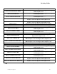
Ordering Guide Model Number Description IMACS-200-RDNT-48VDC-OHSU IMACS 200 System with two -48 VDC Power Supplies and a 2-port OHSU daughter card IMACS-200-48VDC-OW IMACS 200 System with single -48 VDC Power Supply and an Optical WAN daughter board. IMACS-200-RDNT-48VDC-OW IMACS 200 System with two -48 VDC Power Supplies and an Optical WAN daughter board. IMACS-200-48VDC-OHSU-OW IMACS 200 System with single -48 VDC Power Supply, a 2-port OHSU daughter card and an Optical WAN daughter board.
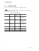
Available Cabling Running Head 14 Model No. Available Cabling Table 2 describes the cables recommended for use with the IMACS-200 unit. Note: Zhone recommends that shielded cables be used to reduce interference that can be caused by lightning surge interference. Table 2.
Table of Contents Table of Contents 1 2 3 4 5 6 7 8 9 10 11 12 13 14 Chapter 1 System Overview 1.1 1.1.1 Chapter 2 Introduction ....................................................................................................1-1 IMACS-200 Chassis ...................................................................................1-1 System Installation 2.1 2.2 2.2.1 2.2.2 2.2.2.1 2.2.3 2.2.3.1 2.2.3.2 2.2.4 2.3 2.4 2.4.1 2.4.2 2.4.3 2.4.4 2.4.5 2.4.6 2.4.7 2.4.
Model No. Running Head Table of Contents 2.5 Power and Grounding on the IMACS-200 .................................................. 2-13 2.5.1 Power Supply and Ringing Generator ..................................................... 2-13 2.5.1.1 Ringing Generator ............................................................................... 2-13 2.5.2 System Power (Redundancy)................................................................... 2-14 2.5.3 AC Power Supply and DC Power Supply Fuses .........
Table of Contents 3.11.1 3.11.2 3.12 3.12.1 3.12.2 3.13 3.14 3.15 3.16 Chapter 4 IMACS-200 General Features 4.1 4.2 4.3 4.3.1 4.3.2 4.3.2.1 4.3.3 4.4 4.4.1 4.4.2 4.5 4.6 4.7 4.7.1 4.7.2 4.7.2.1 4.7.2.2 4.7.2.3 4.7.2.4 4.7.2.5 4.7.2.6 4.7.2.7 4.8 4.8.1 4.8.2 4.8.2.1 4.8.3 4.9 4.9.1 4.9.2 4.9.3 4.10 4.11 Table of Contents Assigning a Time Slot to a User port Port................................................3-27 Cross-Connect Model .......................................................................
Model No. Running Head Table of Contents Chapter 5 WAN ports 5.1 5.2 5.3 5.3.1 5.3.2 5.3.3 5.3.4 5.3.5 5.4 5.5 Chapter 6 FXS Ports 6.1 6.2 6.2.1 6.3 6.3.1 6.3.2 6.4 6.5 Chapter 7 Introduction ................................................................................................... 8-1 SRU port User Screens and Settings ............................................................. 8-1 Test Screen ................................................................................................
Table of Contents 9.2 9.2.1 9.3 9.3.1 9.3.2 9.4 9.5 Chapter 10 HSU Ports .......................................................................................................9-1 HSU Port Cables.........................................................................................9-2 HSU Card User Screens and Settings ............................................................9-2 HSU Card Main Screen ..............................................................................
Model No. Running Head Table of Contents 13.2 13.2.1 13.2.2 13.2.3 13.2.4 13.3 13.3.1 13.3.2 13.4 13.4.1 13.5 13.5.1 13.5.2 Chapter 14 OWAN Port ................................................................................................. 13-1 OWAN Port Description.......................................................................... 13-1 OWAN Alarms ........................................................................................ 13-2 OWAN LED Indications ................................
Table of Contents A.4.4 A.4.5 A.4.6 1.5 SRU port Specifications ............................................................................ A-8 HSU Port Specifications............................................................................ A-9 OHSU port Specifications ....................................................................... A-10 IPR Server Specifications ............................................................................ A-11 Appendix B Error Messages B.1 Introduction ......
Running Head Table of Contents 8 Model No.
List of Figures List of Figures 1-1 1-2 2-1 2-2 2-3 2-4 2-5 2-6 3-1 3-2 3-3 3-4 3-5 3-6 3-7 3-8 3-9 3-10 3-11 3-12 3-13 3-14 3-15 3-16 3-17 3-18 3-19 3-20 3-21 3-22 3-23 3-24 3-25 3-26 3-27 3-28 3-29 3-30 3-31 4-1 4-2 4-3 IMACS-200 Front Panel.......................................................................................................1-1 IMACS-200 Rear Panel ........................................................................................................1-2 IMACS-200 Front Panel..........
Running Head List of Figures 4-4 4-5 4-6 4-7 4-8 4-9 4-10 4-11 4-12 4-13 4-14 4-15 4-16 4-17 4-18 4-19 4-20 4-21 4-22 4-23 5-1 5-2 5-3 5-4 5-5 5-6 5-7 5-8 5-9 5-10 6-1 6-2 6-3 6-4 7-1 7-2 7-3 7-4 7-5 7-6 7-7 7-8 8-1 8-2 8-3 8-4 9-1 9-2 2 Model No. Adding a User ...................................................................................................................... 4-7 Login Log Sample Display ..................................................................................................
List of Figures 9-3 9-4 9-5 10-1 10-2 10-3 10-4 10-5 11-1 11-2 11-3 12-1 12-2 12-3 12-4 12-5 12-6 12-7 12-8 12-9 13-1 13-2 13-3 13-4 13-5 13-6 13-7 13-8 14-1 14-2 Local DTE Loopback............................................................................................................9-7 Local Network Loopback .....................................................................................................9-8 HSU Port Test Screen ....................................................................
Running Head List of Figures 4 Model No.
List of Tables List of Tables 1 2 2-1 2-2 2-3 2-4 2-5 2-6 2-7 2-8 2-9 2-10 2-11 3-1 3-2 3-3 3-4 3-5 3-6 4-1 4-2 4-3 4-4 4-5 4-6 4-7 4-8 4-9 4-10 5-1 5-2 5-3 5-4 5-5 5-6 6-1 6-2 6-3 6-4 6-5 7-1 7-2 IMACS-200 Ordering Guide. ........................................................................................... I-vii Recommended cables ...................................................................................................... I-viii Minimum Chassis Clearances .................................
Running Head List of Tables 7-3 7-4 7-5 8-1 8-2 8-3 8-4 8-5 9-1 9-2 9-3 9-4 9-5 10-1 10-2 10-3 11-1 11-2 12-1 12-2 12-3 12-4 12-5 12-6 12-7 12-8 13-1 13-2 13-3 13-4 13-5 13-6 13-7 2 Model No. Test Screen Actions ........................................................................................................ 7-11 Test Screen Option Settings and Defaults........................................................................ 7-11 Status Information Field Settings...................................
System Overview Introduction Chapter 1 System Overview 1.1 Introduction This chapter describes chassis used by the IMACS-200. The IMACS-200 is available with redundant power supplies which operate in a load-sharing mode. The IMACS-200 chassis is manufactured to be RoHS-compliant. The IMACS-200 comes “Industrial hardened” to operate under more extreme temperature ranges of -40 degrees Celsius to +70 degrees Celsius (-104 degrees Fahrenheit to +158 degrees Fahrenheit). 1.1.
Model No. System Overview Running Head Introduction The IMACS-200 offers a range of power input options, which are selected to be the most commonly used input voltages in use by our various customers. They are: -48VDC, 125VDC, 120VAC and 220VAC. The power supply modules are factory installed, and will come with the proper connectors configured for the IMACS-200 powering options you have selected. The power inputs are to the right and left rear of the IMACS-200, and labeled accordingly.
System Installation Introduction Chapter 2 System Installation 2.1 Introduction This chapter provides instructions for unpacking and installing the IMACS-200 chassis at the user site. It also includes other information you will need to properly install the system and refers you to other chapters for additional port-level information. The system can operate on either AC or DC power when equipped with the proper power supply.
RunningInstallation Head Chassis 2.2.2 Pre-Installation Tips 2.2.2.1 Installation Checklist Model No. System Installation Install your IMACS-200 in the following sequence: 1. Choose a suitable location for the system, as described in this chapter. 2. Unpack and inspect the equipment for damage. 3. Mount the chassis on the desired surface (rack, tabletop, or wall). 4. Install the chassis ground connections. 5. Verify the voltage ratings of all power supplies in the chassis. 6.
System Installation Chassis Installation Be sure to locate the system near all external equipment to which you will connect it. Cable lengths and physical/electrical characteristics are critical to system operation, especially for data signal interfaces. Generally, higher data rates require shorter cables than lower data rates. Also, you must use T1-grade cables for all system connections to those networks.
Model No. System Installation RunningInstallation Head Chassis Figure 2-1.IMACS-200 Front Panel Figure 2-2.Mounting Bracket Holes The chassis have eleven holes on each side, as shown in Figure 2-3. Eight of these holes facilitate mounting in a 19- or 23-inch rack (48.2 or 58.4 cm). You can attach the front, or middle of this chassis to a rack, using the mounting brackets as previously shown.
System Installation Connector Types Figure 2-3.Chassis Mounting Holes Table 2-1 outlines the minimum clearance that is recommended for the IMACS-200 on all four sides. Table 2-1. Minimum Chassis Clearances 2.3 Clearance Front Rear Inches Centimeters 10 25 10 25 Connector Types The product is equipped with several types of electrical connections to the network and power sources.
Model No. System Installation Running Head Connector Types Table 2-2. Front panel connectors Connector Name Connector Type Description Ethernet RJ45 Ethernet port for remote management over IP. Serial RJ45 Asynchronous craft port for local management. Table 2-3. Back panel connectors Connector Name Connector Type Description Voice 50 pin amphenol Four E&M lines, transmit only (to) in the introductory offering of the IMACS-200. Each line utilizes eight leads from the connector.
System Installation 2.4 Connector Pin-outs Connector Pin-outs Following is a description of the various connectors and their respective pin-outs. 2.4.1 High Speed Data port connector pinouts Table 2-4 describes the signals and pins for the V.35 data ports. The pin assignments are associated with the use of Zhone cable part number 1216M (F). Table 2-4. V.
Model No. System Installation Running Head Connector Pin-outs Table 2-4. V.35 DB25 female connector Pin Signal Source V.35 (with PRM-1261F cable) 23 External Transmit Clock A 24 Terminal Timing A Not Used U 25 Test Mode DCE NN Note: For purposes of connection and function, the IMACS-200 should be considered a DCE. 2.4.2 E&M, FXS and Alarm input connector Table 2-5 lists the connector pinouts for the E&M circuits, FXS circuit and the provided alarm input points.
System Installation Connector Pin-outs Table 2-5.
Model No. System Installation Running Head Connector Pin-outs Table 2-6. T1 connector pinouts RJ-45(F) Pin Signal 1 R1 2 T1 4 R 5 T 3, 6, 7, 8 Not assigned 2.4.4 Ethernet connections Table 2-7 lists the RJ45 connector pinouts for the ethernet ports on the front and rear of the chassis. Table 2-7. Ethernet connector pinouts RJ-45(F) Pin Signal 1 TXP 2 TXN 3 RXP 4 TXCT 5 RXCT 6 RXN 7 Not used 8 Ground 2.4.
System Installation Connector Pin-outs Table 2-8. Sub Rate Data (SRU) ports connector pinouts RJ-45(F) Pin Signal Direction 6 TXD Input 7 CTS Output 8 RTS Input 2.4.6 Alarm Output Connector The IMACS-200 is equipped with an RJ45 connection on the rear faceplate labelled ALARM to drive external alarm responders such as buzzers, bells, and lights. Table 2-9 indicates the pin-outs for this RJ45 connector.the T1 RJ45 connector pinouts. Table 2-9.
Running Head Connector Pin-outs 2.4.8 Model No. System Installation Connecting Cables to the ports Connect system ports to the external equipment, using the proper cables. The ports have various types of connectors for those connections. Voice ports have a 50-pin Amphenol-type jack. To connect a cable to this type of jack, first plug the male connector of the cable into the jack and push it in all the way.
System Installation Power and Grounding on the IMACS-200 2.5 Power and Grounding on the IMACS-200 2.5.1 Power Supply and Ringing Generator The power supply and ringing generator system can consist of up to two power supplies, and has one on-board ringing generator. The IMACS-200 comes with the proper power supplies factory-assembled depending on the ordering information provided at the time of purchase. 2.5.1.1 Ringing Generator The Ringing Generator on the IMACS-200 outputs 86Vrms at 20Hz.
Running Power andHead Grounding on the IMACS-200 2.5.2 Model No. System Installation System Power (Redundancy) The IMACS-200 provides power redundancy for any of the powering options. The supplies are factory-installed, and the external connectors to receive the powering options selected will be pre-installed on the unit. Figure 2-4 on page 2-5 high-lites the location of the Power Supply feeds.The 120VAC and 220VAC power inputs are lightly shaded, and the -48VDC and 125VDC options are darkly shaded. 2.
System Installation Power and Grounding on the IMACS-200 The telecommunications voice signaling ground is a referenced ground connection to the -48VDC power system. Both feeds are referenced to the same place within the IMACS-200. This reference ground can occur at the -48VDC power source.
Running Power andHead Grounding on the IMACS-200 2.5.8 Model No. System Installation AC power installation If ordered as an AC unit, the IMACS-200 will come pre-assembled with one or two AC connectors on the rear panel, as illustrated in Figure 2-4 on page 2-5. To apply the AC source to the unit, simply use the supplied AC cords included in the packaging to connect the IMACS-200 to the 120VAC or 220VAC source. 2.5.
System Configuration and Operation Basic Operations Chapter 3 System Configuration and Operation 3.1 Basic Operations This chapter provides instructions for configuring the IMACS-200 for operation after installing it at the equipment site. Before performing the procedures in this chapter: 1. Be sure your IMACS-200 is installed and powered up. 2. Determine your system’s specific configuration requirements. These depend on your network and customer premises equipment (CPE) interfaces.
Model No. System Configuration and Operation Running Head System Power-up 3.3.1 System Boot Following the application of power, proceed as follows: 1. Be sure your system and local terminal are both powered up. 2. Connect a VT100-compatible terminal to the SERIAL jack on the faceplate of the IMACS-200 front panel. Use a cable with an RJ-45 modular plug on one end for this connection. 3. Configure the terminal to operate at 9.6 kbps, 8 data bits, no parity, and 1 stop bit.
System Configuration and Operation 3.3.2 System Power-up Logging Into the System The first step in starting a user session is to log into the system. You must enter a password that allows you to perform the required tasks on the system. For access levels and user permissions, refer to the section detailing user access in Section 4.3.2 on page 3 of Chapter 4 IMACS-200 General Features. To log into the system from a local terminal, proceed as follows.
Running Head System Power-up Model No. System Configuration and Operation 5. Once system access has been obtained, the IMACS 200 will prompt the user to assign WAN and OWAN (if provisoined) port defaults. All four of the WAN or OWAN ports must be set to the same interface type (T1 or E1). This main screen is shown in Figure 3-3. Currently, the OWAN and WAN must be set to the same interface type, either E1 or T1. Caution should be exercised when choosing the interface type to the WAN and OWAN.
System Configuration and Operation System Power-up Figure 3-4.Typical System Main Screen This completes the login process. If you are not familiar with the user interface screens of the system, read the next section before proceeding. Otherwise, continue with the desired operation.
Model No. System Configuration and Operation Running Head System Screens 3.4 System Screens The system screen will display each port that is currently installed onto the system along with the port status and location. 3.4.1 System Main Screen After you log in, a System Main Screen Figure 3-6 appears, showing all of the ports currently in the system. The port types and current port operational states also appear in this screen. The highlighted line at the bottom of the screen lists some actions.
System Configuration and Operation System Screens Figure 3-5.Typical port Status Display From the System Main Screen, you can also access other screens, as shown in Figure 3-5. These screens are described in the following paragraphs. 3.4.3 Service Type Main Screens Each port type in the system has a port Main Screen associated with it. You can go from the System Main Screen to any port Main Screen and configure that device.
Running Head System Screens Model No. System Configuration and Operation The port configuration parameters and current option settings appear in numerous rows and columns below the header. This region of each screen lists the options on the left and one or more associated columns of data fields from left to right. You can change the settings in those fields as required for each port. The status and data entry change line appears just above the bottom line of the screen.
System Configuration and Operation System Screens The highlighted area in the upper right corner shows the current alarm status data. In Figure 3-6 below, a yellow alarm has occurred on WAN port 4, and a Loss of Signal alarm has been detected on WAN port 3. Figure 3-6.Typical port Main Screen The bottom line of each port Main Screen lists other actions you can perform by simply pressing the letter key that corresponds to the uppercase letter of your desired action.
Running Head Port Configuration 3.4.4 Model No. System Configuration and Operation Test and Debug Screen You can also go from the System Main Screen to a Test and Debug Screen, which allows you to perform system-level maintenance operations. You can back up the system configuration onto an external computer after saving and subsequently editing it, and (if necessary) you can restore that configuration to the system.
System Configuration and Operation 3.5.2 Port Configuration Recording Your Configuration Settings You should always record the configuration option settings for each port after you set them. This information may be needed later for system operation. To record the port configuration data, first photocopy the pages showing the port Screens in the associated chapters of this guide.
Running Headthe System Reinitializing 3.6 Model No. System Configuration and Operation Reinitializing the System The system stores information about its currently installed ports, the port configuration option settings, WAN connections, passwords, and other data in nonvolatile memory (NVRAM). When you change any settings on the port types, the NVRAM remembers the previous port settings. Restart capability is available on the IMACS-200.
System Configuration and Operation Reinitializing the System . Figure 3-8.System Screen - Test and Debug. Once here, enter ‘Z’ to zip the system, and the screen seen in Figure 3-9 will appear. Figure 3-9.Cold-Start NVRAM “Zip”Test and Debug Screen. WARNING! Confirming the "Z" command will start the ZIP process. "Zipping" the system deletes all of the information stored on NVRAM and resets it. All ports must then be completely reconfigured.
Model No. System Configuration and Operation Running Head Alarms When you press “z”, the system will ask, "OK to Zip the system (y/n)"? Press “y” to have the system test and re initialize itself. All NVRAM information will be erased from the IMACS-200, and a new log-in screen will appear. Since the user names and passwords are maintained over the zip function, the user will be able to login as normal. Also maintained over the zip function are the IP address(es) saved in the unit. 3.
System Configuration and Operation Alarms The third character set is the alarm modifier (in this case, m indicates a minor alarm). See the “Alarms and Alarm Filters” section later in this chapter for more information about alarm modifiers. The fourth character set (YEL) is the type of alarm generated (in this case, a Yellow alarm on WAN port WAN-4). The last two character sets are the date and time the alarm was logged.
Model No. System Configuration and Operation Running Head Alarms 3.7.2 Alarm Filter Settings You can set filters for each alarm so that the alarm reports occurrences in a number of different ways. Figure 3-11 shows the Alarm Filters screen, which is accessed by pressing "f" (Filters command) on the Alarm Screen. Figure 3-11.Alarm Filters Screen The first column of the Alarm Filters Screen is the alarm abbreviation that appears when an alarm is generated.
System Configuration and Operation Alarms Table 3-2. Alarm Filters Filter NOS LOS YEL Alarm No Signal Loss of Synchronization Yellow Alarm AIS Alarm Information Signal CGA_RED Carrier Group Alarm - Red CGA_YEL Carrier Group Alarm - Yellow ERR Excessive Error Rate SENSOR Alarm port Sensor HI-TEMP Temperature Alarm FANFAIL UCA Cooling Fan Failure User port/port alarm RESET System reset ACO Alarm Cut-Off SYNC Clock Sync Alarm Meaning Incoming WAN signal is lost. Frame Alignment is lost.
Running Head Alarms Model No. System Configuration and Operation When interfacing to the External Alarm ports, the occurrence of any alarm designated as crit will trigger a form-C relay contact on the External Alarm port. The relay contact action sets off an annunciator or lamp at the equipment site. Similarly, the occurrence of any alarm designated as major triggers a different contact and activates another external indicator.
System Configuration and Operation Cross-Connecting (XCON) Figure 3-12.Typical Alarm History Screen 3.8 Cross-Connecting (XCON) From the System Main Screen, you can access a Cross-Connect Screen by pressing “x” (Xcon) that lets you cross-connect WAN time slots between T1 links. For a detailed description of making connections on and through the IMACS-200, see Section 3.10 on page 25 for information regarding making and managing cross-connects. 3.
Running HeadMaintenance System Level Model No. System Configuration and Operation Figure 3-13.
System Configuration and Operation 3.9.2 System Level Maintenance Debugging the System The D (Debug) command is only available to factory personnel with a password authorization higher than "Superuser." It gives access to the system software coding. 3.9.3 Backing up the System Configuration Data The IMACS-200 provides the capability to backup the system configuration to a PC or network service device.
Running HeadMaintenance System Level Model No. System Configuration and Operation I P and netmask parameters must be set. You may need to change the routing table on your PC to include the IMACS-200 ethernet address as the gateway, or the local host address as the gateway for the system receiving the file as the destination IP address, Figure 3-15.Setting the Host IP address Note: 3.9.
System Configuration and Operation System Level Maintenance 5. Press “G” for Go - an NV image overwrite command confirmation appears. Enter “Y” for yes. 6. Confirmation appears when the NV Ram flash backup is complete. Press Enter as prompted on the screen. 7. TFTP backup is now ready to proceed. Select TFTP by highlighting the appropriate protocol using the arrow keys. Press Enter when TFTP is highlighted. 8. Press “G” for Go. 9. A series of four questions must be answered to complete the backup process.
Running HeadMaintenance System Level Model No. System Configuration and Operation 3. Use the arrow keys to highlight the Protocol selection and press Enter. 4. Select TFTP and press Enter. 5. You will receive an NV Ram image overwrite confirmation message. Press “Y” for yes. 6. Enter the desired number of Mismatch retries and press Enter. 7. Enter the desired number of Timeout Retries and press Enter. 8. Enter the IP address of the PC or TFTP server and press Enter. 9.
System Configuration and Operation Time Slot Assignment 9. A system backup completion message appears and the system then prompts you to press Enter to continue. The backup is now complete. 3.9.8 XMODEM Restore Follow the steps listed below to perform an XMODEM restore. Note: Restore actions may be denied, based on several factors.
Running Head Assigning Time Slots Model No. System Configuration and Operation The IMACS-200 maximizes the use of incoming and outgoing T1 lines. You can do this by assigning specific channels, or DS0 time slots, to voice and data ports in the system. You also can cross-connect time slots between T1WAN ports of the system. The WAN port allows you to connect one DS0 time slot to another.
System Configuration and Operation Assigning Time Slots 3.11.1 Assigning a Time Slot to a User port Port You can define a time slot map from any user port (data or voice) for connections involving that port, or from a WAN port for cross-connections involving only WAN ports. For example, Figure 3-16 shows the E&M port Main Screen for the time slot assignments. Assign time slots to a voice port as follows: 1. From the System Main Screen, select the desired voice port and press .
Model No. System Configuration and Operation Running Head Circuit Names 3.11.2 Cross-Connect Model The Cross-connect model allows you to access one T1 links for each of two WAN ports, for a total of four T1 links. All WAN port connections to other WAN ports are accomplished through the cross-connect option on the System Main Screen, and must be individually specified. 3.
System Configuration and Operation Circuit Names Figure 3-17.Cross Connect Screen Circuits are then selected by moving the arrow keys up and down. Only network type circuits are shown on the first Cross Connect screen. To display a list of all cross connects in the IMACS-200 system from the Cross Connect screen, select "View All". Below is a sample of this screen.Note that this is page one of two. Using the ‘d’ for pageDown and ‘u’ for pageUp will display more pages.
Running Head Circuit Names Model No. System Configuration and Operation Figure 3-19.Cross Connect Circuit (Rename) Hitting "S" to save the circuit name changes the name of the circuit as shown in the below figure: Figure 3-20.Cross Connect Rename Circuit (Saving) 3.12.2 Backup and Restore Circuit Name Table The circuit name table can be backed up and restored via VNVRAM, adding additional flexibility for managing circuit names.
System Configuration and Operation Circuit Names Figure 3-21.NVRAM Backup Screen When NVRAM is restored via TFTP or from FLASH, the entire image is transferred including the circuit name table. The circuit name table shown as Xcon Names has been added to the selections to allow ascii restore as shown in the figure below. Figure 3-22.NVRAM Restore Screen Upon restoring the Xcon Names table, changed circuit names will be restored into NVRAM for recognition whenever the resource using it is next changed.
Running Head Cross-Connecting WAN Time Slots Model No. System Configuration and Operation 3.13 Cross-Connecting WAN Time Slots After assigning the user ports to DS0 time slots, you can also assign the remaining WAN time slots for pass-through cross-connections betweenT1 links. You can cross-connect WAN time slots from the System Main Screen. To perform cross-connections, press “x” in that screen to invoke the Xcon command. The Cross-Connect Screen in Figure 3-23 appears.
System Configuration and Operation Cross-Connecting WAN Time Slots Table 3-4. Time Slot Cross-Connection Options and Defaults Parameter CIRCUIT ID W/U TS/BW W/U TS/BW SIG/TC User Options Any combination of letters or numbers up to 14 characters, including spaces wan-1 wan-2 wan-3 wan-4 table wan-1 wan-2 wan-3 wan-4 table Default ************** wan-1 00 wan-1 00 CIRCUIT ID A circuit is defined as a group of one or more DS0 time slots cross-connected from one WAN link to another.
Running Head Cross-Connecting WAN Time Slots Model No. System Configuration and Operation WARNING! When cross-connecting multiple independent data DS0 time slots (sequentially grouped time slots should work) for data. Super-rate [data type cross-connect] is multiple DS0s sequentially assigned between WAN aggregates in a cross-connect system. DO NOT attempt to save time by cross-connecting independent data time slots as one super-rate circuit (could cause data errors.
System Configuration and Operation Cross-Connecting WAN Time Slots The example in Figure 3-26 shows wan-1 as the selected WAN port. Figure 3-26.WAN Unit Options TS/BW The first Time Slot/Bandwidth column shows the different time slots of wan-1 that will be assigned to this pass-through connection. Figure 3-27 shows the selection of time slots 8 to time slot 12 of wan-1 assigned to the start of the connection. Any number of time slots from 1 to 24 is allowed for T1 transmission.
Running Head Cross-Connecting WAN Time Slots Model No. System Configuration and Operation Make your selection by using the space bar and arrow keys. The arrow key moves from slot to slot, and the space bar toggles between selecting and deselecting a time slot. Figure 3-27.Time Slot and Bandwidth Options W/U The second WAN Unit column is the T1 link in which the pass-through connection ends. The options are all of the WAN ports and ports.
System Configuration and Operation Cross-Connecting WAN Time Slots SIG/TC You can define a pattern to be transmitted on a cross-connected circuit if one of the circuit’s two WAN links fails on a WAN to WAN cross-connect. This is known as Trunk Conditioning (TC), and can be assigned for the transport channels. For circuits that terminate locally in the IMACS-200, the field is populated as n/a, for not applicable. The SIG/TC choices are shown in Figure 3-28.
Running Head Cross-Connecting WAN Time Slots Model No. System Configuration and Operation If you choose user, also enter a two-digit hexadecimal code for the bit pattern to be sent in each direction. Each digit can be from 0 to 9 or a to f. Figure 3-29 shows a typical signaling bit pattern entry screen. Figure 3-29.Options with choosing User Trunk Conditioning Once a service has been selected on the SIG/TC screen, you will then need to select the idle or busy pattern to send on a CGA event.
System Configuration and Operation Cross-Connect Actions 3.14 Cross-Connect Actions Figure 3-5 summarizes the actions you can perform from the Cross-Connect Screen. These actions appear at the bottom highlighted line of the screen. Table 3-5. Cross-Connect Screen Actions Action Function Add Allows you to program additional pass-through cross-connects in the system. If mistakes are made during the add process, pressing the up arrow or down arrow key will terminate this operation.
Running Head Actions Cross-Connect Model No. System Configuration and Operation To update a cross-connected circuit from the Cross-Connect Screen, highlight the circuit name to be updated, and press “p” to invoke the uPdate command. Figure 3-26 shows the WAN port 1-3 and TS (time slots) 6 through 8 being updated. However if the WANs are selected and deleted as shown in Figure 3-31 then the screen in Figure 3-27 will be blank for WAN TS 6 through 8.
System Configuration and OperationRecording the Time Slot Configuration 3.15 Recording the Time Slot Configuration After setting up the initial system configuration and define the time slot map, record this information on paper. Recording the initial configuration in a logical manner will help if you have a problem later. Record the information in a way that makes sense to you and will be easy for others to understand.
Running HeadRedundancy Power Supply Model No. System Configuration and Operation feeds into the IMACS-200, the power supply fail alarm will be raised. Both the AC and DC versions of the IMACS-200 can have backup power feeds and supplies, if so ordered. Upon failure, the ALARM LED on the faceplate of the IMACS-200 will be turned on and a system alarm will be generated.
IMACS-200 General Features Introduction Chapter 4 IMACS-200 General Features 4.1 Introduction The main login level of the IMACS-200 is the highest level and allows access to Alarms and alarm filtering, overall cross-connect information, and access to backup and restore functions. 4.2 CPU Descriptions The main CPU level is accessed as soon as a user logs into the IMACS-200. This main screen is seen in figure Figure 4-1. Figure 4-1.
Running CPU UserHead Screens and Settings 4.3 Model No. IMACS-200 General Features CPU User Screens and Settings The IMACS-200 main CPU has several user interface screens for port configuration and network status viewing purposes. These screens are described in the remainder of this chapter. 4.3.1 CPU Main Screen Figure 4-2 shows the CPU interface Main Screen. You must configure the CPU interface after logging into the system for the first time.
IMACS-200 General Features CPU User Screens and Settings Table 4-1. CPU Main Screen Actions Action Function Save Undo Refresh Saves changes to settings. Returns all settings to the last saved state. Updates certain time-related information fields that are not automatically updated (i.e., performance and test data). tcp/Ip Allows the user to configure for TCP/IP functionality. usrNames Allows additions to user names, groups, password administration.
Model No. IMACS-200 General Features Running CPU UserHead Screens and Settings When the system is first commissioned, there is only one group defined: Table 4-3. Default User Table Default User Name admin Default Password Default User Group admin 1 Each user group represents a different access level that allows a login id to perform system certain tasks after logging in. 4.3.2.
IMACS-200 General Features CPU User Screens and Settings When the system is first commissioned, or after a ZIP function, the user group defaults to the following configuration: 1 2 - 32 RW R RW R RW R RW R RW R RW R RW R Administer Users Administer System Access PMs Access Alarms Access Provisioning WAN PMs WAN Alarms WAN Provisioning User Group Number Table 4-5. Default Group Permissions RW R User group 1 is the "Superuser" and its attributes are not provisionable.
Running CPU UserHead Screens and Settings Model No. IMACS-200 General Features Figure 4-3.User Name Screen Table 4-6 shows the valid actions that a user can perform when at the user name field.
IMACS-200 General Features CPU User Screens and Settings Table 4-6. usrName Screen Actions Action Function Refresh Add Del Group Re-paints the current screen Allows you to add a user Allows you to delete a user Displays the Group settings and access level permissions as explained in Section 4.3.3 on page 9. Login Log Provides the last 20 login and logout events. pgup Pages up pgdn Pages down. Main Returns you to the CPU Main Screen.
Running CPU UserHead Screens and Settings Model No. IMACS-200 General Features Del Selecting the ‘E’ delete function will allow the user to delete the user that the cursor is currently positioned upon. Group Selecting ‘G’ will show the permissions for access to a Superuser that can be changed. These are outlined in Section 4.3.3 on page 9. Login Log Selecting ‘L’ will take the user to a screen where the login log is stored.
IMACS-200 General Features 4.3.3 CPU User Screens and Settings Access Level Permissions With the Admin level user, the Group setting can be changed on a group basis. Begin by accessing the User Name Screen as shown in Figure 4-3 on page 4-6. Select the Group option by typing “G”, and a screen such as in Figure 4-6 appears Figure 4-6.Group Permissions Settings Use the arrow keys to select the field and permission that you want to change, and access the write capability by issuing a carriage return.
Running Head Other CPU Settings Model No. IMACS-200 General Features Access Provisioning This covers all provisioning screens and activities associated with all the access interfaces. This includes OHSU, HSU, SRU, voice, alarm, and Ethernet posts Access Alarms This covers all alarm reporting screens and activities associated with all the access interfaces. This includes OHSU, HSU, SRU, voice, alarm, and Ethernet posts. Read access allows alarms to be viewed only.
IMACS-200 General Features Other CPU Settings Figure 4-7.Other CPU Fields and Settings Refer to Figure 4-7 for the following field definitions and their meanings. NODE ID In this field, enter a 14-character node name for the Integrated Access System. This entry must be unique for each system in your network. It can have alphanumeric characters and spaces. SUPERUSER This field displays the current password for Superuser SNMP access. Only the Superuser should see this field.
Running Head Other CPU Settings Model No. IMACS-200 General Features VIEWER This field displays the current password for Viewer SNMP access. All users can see this field. This password level gives read only access to configuration options and diagnostic features. SYS CONT In this field, enter the name of a person to contact for questions about the Integrated Access System. This field can have up to 23 alphanumeric characters, including spaces.
IMACS-200 General Features Other CPU Settings FCR Fast Circuit Restore. This field can be set to on or off, the default is off. When set to off, normal T1 recovery modes are in effect. When set to on, the services will restore as soon as the facility becomes available for service. Selecting to on will typically recover data services in 200 ms, and voice services after one second. HW Rev.
Running Head Other CPU Settings 4.4.1 Model No. IMACS-200 General Features System Clock Source Figure 4-8.Setting the System Clock Source The IMACS-200 can be set to source to an incoming timing source from the WAN, the HSU, the optional OWAN, or on its internal clock. Figure 4-8 shows this setting from the CPU Clock screen. Choosing one of the three choices and saving the choice will force the system to time off of that source.
IMACS-200 General Features 4.4.2 Other CPU Settings Setting the System Time Figure 4-9.Setting the System Time From the Clock level of the CPU, the user can set the date and time as shown in Figure 4-9. From this same level, the crafts person can execute the Alarm Cut Off (ACO).
Running Head Management SNMP Network 4.5 Model No. IMACS-200 General Features SNMP Network Management SNMP access allows users to remotely gather information, provision, test and monitor the IMACS 200. This section presents this type of Network Management System (NMS) for diagnosing and reporting trouble at unsupervised locations. The SNMP alarm traps and configuration can connect using this alternate method. Both formats can use either the SA4 on an E1 link, or a full DS0 on a T1 or E1 link.
IMACS-200 General Features SNMP Network Management You can change your Manager, Operator, and Viewer passwords at any time. See your system administrator to change your password or access levels. A user who has read/write access to the Administer System system function (see Table 4-4 on page 4-4) will have the ability to see and update all of the Passwords / Community Names used for SNMP access.
RunningNetwork Head Management TCP/IP 4.6 Model No. IMACS-200 General Features TCP/IP Network Management Using IP addresses, you can communicate directly with the affected system, diagnose the problem, and dispatch a technician if necessary. Figure 4-10shows the TCP/IP Screen. To access this screen, press “I” (tcp/Ip) in the CPU Card Main Screen. Table 4-8 summarizes the actions that can be performed from this screen, and Table 4-9 lists the TCP/IP Screen parameters and options. Figure 4-10.
IMACS-200 General Features TCP/IP Network Management Table 4-8. TCP/IP Screen Actions Action Ping Netstat rOute Save Undo Refresh Main Function Test whether the connected device responds to an echo request message. After entering the IP address of the host device, the status line will display, "Testing . . ." The next message indicates if the host is alive or down. Displays the Network Statistics. See below. Shows the Routing screen. See the “Routing” section below. Saves changes to settings.
RunningNetwork Head Management TCP/IP Model No. IMACS-200 General Features DEFAULT IP SLOT The Default IP Slot options are determined by the choice of Default IP Port. If none, local ether or ipr-fr is selected for that parameter, this option will show n/a. If wan or sa4 is selected, the options for this parameter will show wan-1 through wan-4(the WAN card slot that transmits and receives NMS information). DEFAULT IP TS The Default IP Unit options are determined by the choice of Default IP Slot.
IMACS-200 General Features Remote Administration RPT3 IP ADDR The RPT3 IP Address is the IP address of the third Network Management System host running an SNMP trap server. RPT3 COMMUN STR The RPT3 Community String holds the community string for the third NMS host running a SNMP trap server. The community string provides additional security by rejecting messages that do not contain the correct string. There must be an entry in this field to enable RPT3. 4.
RunningAdministration Head Remote Model No. IMACS-200 General Features 4. Enter in the HOST NETMASK: [IP mask] 5. Select the HOST TYPE as either host or gateway. As a host system, the IMACS-200 terminates the IP when packets are destined for its address. As a gateway, the IMACS-200 has the ability to perform packet-forwarding to another destination.When choosing the gateway option, the user can only select WAN as the Default IP type.
IMACS-200 General Features Remote Administration b. Choosing Host type as gateway will set up the downstream management channel, or SCC4. The IP static route must be set via the rOute option after you have saved the above. To set up a static route, choose the rOute option from the tcp/Ip screen and choose the add option, stepping through the required fields as shown in Figure 4-14. This route will setup the SCC4 connection for the forwarded IP packets.
RunningAdministration Head Remote Model No. IMACS-200 General Features b. Telnet [device IP address] 12. From the IMACS-200: a. Ping PC on IP network 13. From a PC on a different network than the IP network: a. Ping [device IP address] b. Telnet [device IP address] 14. From the IAD, Ping PC on the network different from IP subnetwork. 4.7.2 Network Statistics Screens The Network Statistics Screens provide maintenance and diagnostic information for the different protocols supported by this equipment.
IMACS-200 General Features Remote Administration To move from one screen (page) to another, press “d” (pgDn) or “u” (pgUp). Pressing “d” goes to the next-highest page number. If you are on Page 4 when you press “d”, you will wrap around to Page 1. Page 4 is currently not used on the IMACS-200, and therefore present not data. Pressing “u” goes to the next-lowest page number. If you are on Page 1 when you press “u”, you will wrap around to Page 4.
RunningAdministration Head Remote Model No. IMACS-200 General Features Table 4-10. Network Statistics Screen Actions Action pgUp pgDn Refresh Main 4.7.2.1 Function Scrolls backward through network statistics, one page at a time. If you are on the first screen (Page 1), automatically “wraps around” back to the fourth screen (Page 4). Scrolls forward through network statistics, one page at a time. If you are on Page 4, automatically “wraps around” back to Page 1.
IMACS-200 General Features Remote Administration Datagrams Sent The Datagrams Sent field shows the total number of datagrams sent by the local system to the network host. TX Disported - RAM The TX Disported - RAM field shows the total number of datagrams sent by the local system that were disported due to lack of free RAM memory. TX Disported - Mailbox Short The TX Disported - mailbox short field shows the total number of datagrams aborted by the local system because of a mail subsystem overflow.
RunningAdministration Head Remote 4.7.2.2 Model No. IMACS-200 General Features TCP State Parameters The TCP state parameters appear in the third Network Statistics Screen (Figure 4-16). They are described below. Figure 4-16.Typical Network Statistics Screen, Page 2 Packets Received The Packets Received field shows the number of TCP packets received by the local system from the network host.
IMACS-200 General Features Remote Administration Bytes Delivered Above The Bytes Delivered Above field shows the number of information or traps sent from TCP layer of the network host to the local system. Bytes From Above The Bytes From Above field shows the number of information or traps sent to the TCP layer of the network host from the local system. Packets Sent The Packets Sent field shows the total number of TCP packets that were transmitted to the network host by the local system.
RunningAdministration Head Remote Model No. IMACS-200 General Features RTT Decreased The RTT Decreased field shows the number of times the retransmission time-out was decreased because the system was not busy. Connections Opened The Connections Opened field shows the total number of connections that were opened by the local system to the network host. Connections Closed The Connections Closed field shows the total number of connections that were closed by the local system to the network host.
IMACS-200 General Features 4.7.2.3 Remote Administration UDP Parameters The UDP parameters appear in the fourth Network Statistics Screen (Figure 4-17). They are described below. Figure 4-17.Typical Network Statistics Screen, Page 3 Packets From Above The Packets From Above field shows the number of UDP packets sent by the local system to the network host. Packets Sent The Packets Sent field shows the number of UDP packets transmitted from the local system to the network host.
RunningAdministration Head Remote 4.7.2.4 Model No. IMACS-200 General Features TELNET Parameters The TELNET parameters also appear in the fourth Network Statistics Screen (Figure 4-17). They are described below. Bytes Received The Bytes Received field shows the total number of bytes that were received by the local system from the network host.
IMACS-200 General Features Remote Administration Sessions Closed The Sessions Closed field shows the total number of sessions that were closed by the local system with the network host. TX Wait for Buffer The TX Wait for Buffer field shows the total number of transmissions that were delayed by the local system for free memory in the buffer. 4.7.2.5 SNMP Parameters The TELNET parameters also appear in the fourth Network Statistics Screen (Figure 4-17). They are described below.
RunningAdministration Head Remote 4.7.2.6 Model No. IMACS-200 General Features SCC Parameters The SCC parameters for ports C1 through C4 appear in the fourth through seventh Network Statistics Screen (Figure 4-18). They are described below. Figure 4-18.SCC Port Parameters In Packets The In Packets field shows the number of packets received by the local system. In Octets The In Octets field shows the number of bytes received by the local system.
IMACS-200 General Features Remote Administration The In Errors field shows the number of packets received by the local system which had errors and were discarded as faulty. Out Packets The Out Packets field shows the number of packets sent by the local system. Out Octets The Out Octets field shows the number of bytes sent by the local system. Out Discards The Out Discards field shows the number of packets sent by the local system which were unable to be processed and therefore discarded.
Model No. IMACS-200 General Features RunningAdministration Head Remote 4.7.2.7 SA4 Parameters The SA4 parameters appear in the eigth Network Statistics Screen (Figure 4-19). They are described below. Figure 4-19.SA4 Bit Parameters In Packets The In Packets field shows the number of packets received by the local system. In Octets The In Octets field shows the number of bytes received by the local system.
IMACS-200 General Features Host Software Upgrade Procedure In Errors The In Errors field shows the number of packets received by the local system which had errors and were discarded as faulty. Out Packets The Out Packets field shows the number of packets sent by the local system. Out Octets The Out Octets field shows the number of bytes sent by the local system.
Running HeadUpgrade Procedure Host Software 4.8.2 Model No. IMACS-200 General Features Laptop Setup Follow the steps listed below to set up the laptop computer. 1. Boot the laptop. 2. Click “START”. 3. Select “Programs”, “Accessories”, and click on “HyperTerminal”. 4. In the HyperTerminal window, double click on “Hypertrm” icon. 5. In the New Connection window, Enter Name: enter Upgrade. 6. Select icon and click OK. 7. In Connect to Window, Connect Using, click down arrow and select “Direct to COM1”. 8.
IMACS-200 General Features 4.8.3 Software Download Procedures Upgrade Preparation Follow the steps listed below to perform an upgrade. 1. Connect the laptop to the TERM port on the Integrated Access System. 2. Press Enter, and log into the system. 3. Using the arrow keys, move the cursor to CPU and press Enter. 4. Verify and record the current host software version. 4.9 Software Download Procedures 4.9.
Running Download Head Software Procedures Model No. IMACS-200 General Features 8. At the HyperTerminal screen, select file transfer and send the file. Choose the appropriate binary file to download using the XMODEM protocol to BIN buffer 1 or 2, depending upon which bin is empty. 9. Following completion of the download process, make the newly loaded bin active and then erase the existing firmware from the now inactive bin.
IMACS-200 General Features Note: Software Download Procedures When upgrading from a PC, an ethernet cross-over cable will be required. Use the TCPIP settings to put your PC on a network connection (such as 192.0.0.1), and set the IMACS-200 on the same subnet (such as 192.0.0.2). 2. At the Login screen, enter the system password. The Main screen appears. 3. With the cursor on the CPU level, press P. The Flash screen appears with status and data for memory blocks 1 and 2. Figure 4-20.Flash Screen 4.
Running Download Head Software Procedures Model No. IMACS-200 General Features Figure 4-21.Flash Screen with Commands 5. Select the desired command. Press Enter. The activate, download, and erase cannot be performed on the active software. 6. Enter Y to replace the current software. The system removes the current software from the selected block. 7. Select the tftp option. Press Enter. 8. Enter the desired number of mismatch retries. Press Enter. Default value is 20. 9.
IMACS-200 General Features Software Download Procedures Figure 4-22.Flash Screen with Software Removed 10. Enter the IP address of the TFTP server. Press Enter. 11. Enter the firmware filename. Press Enter. The download software appears in the Flash screen. Figure 4-23.Flash Screen with Downloaded Software 12. With the desired software block selected, press Enter. The activate and deactivate options appear at the bottom of the screen. 13.
Running Download Head Software Procedures Model No. IMACS-200 General Features This resets the IMACS-200 and makes the selected software the current active load. Upon reset and activation, you will lose the current Telnet connection.
IMACS-200 General Features CPU Error Messages 4.10 CPU Error Messages Refer to Appendix B in this Guide for further information on Error Messages regarding this port. 4.11 CPU Troubleshooting On power-up, the IMACS-200 performs a self-test. This is the only diagnostic available for the first release of the unit. A “healthy” active IMACS-200 will have a green LED lit on the front panel.
Running Head CPU Troubleshooting 4-46 Model No.
WAN ports Introduction Chapter 5 WAN ports 5.1 Introduction This chapter provides configuration and troubleshooting information for the Wide-Area Network (WAN) ports. There are four WAN ports available on the IMACS-200. The WAN ports manage the flow of data through the IMACS-200 network. They terminate T1or E1 lines and generate or receive network timing clocks. They also cross-connect DS0 time slots, to pass data through the system from one T1or E1 line to another. 5.
Running WAN portHead User Screens and Settings 5.3 WAN port User Screens and Settings 5.3.1 WAN Settings for T1 and E1 Model WAN portsNo. Table 5-1 shows the WAN port Main Screen for T1 operation. Figure 5-1.WAN T1 Port Main Screen Table 5-2 shows the WAN port Main Screen for E1 Operation. Figure 5-2.
WAN ports WAN port User Screens and Settings Table 6-1 summarizes the actions you can perform from this screen, and Table 6-2 lists the settings controlled on the screen along with their possible and default values. Table 5-1. WAN Screen Actions Action Function Save Undo Refresh Saves changes to settings. Returns all settings to the last saved state. Updates certain time-related information fields that are not automatically updated (i.e., performance and test data).
Running WAN portHead User Screens and Settings Model WAN portsNo. FORMAT The Frame setting toggles the frame format to be used on the T1 WAN link so that it matches the frame format used by the T1 carrier. Set the format Parameter based on the type of frame format the T1 carrier requires. The options are d4 (normal superframe) or esf (extended superframe). LINE CODE The Line Code setting matches the Line code used by the T1 interface to that used by the T1 network.
WAN ports WAN port User Screens and Settings LINE LB The Line Loopback setting loops the T1 line back towards the network, as shown in Figure 5-3. This loopback also continues sending the incoming data toward the CPE. Choosing on allows you to test the end-to-end T1 circuit path from the far end. Choosing off disables the loopback and restores the normal signal path in both directions. If the WAN is in loopback due to a remote device, the loopback will be dropped if you choose on. Figure 5-3.
Running WAN portHead User Screens and Settings Model WAN portsNo. LB GEN The Loopback Generate setting (available only in esf format) generates out-band diagnostic codes that are sent to the remote equipment. These codes are compatible with DDS networks and allow you to command a latching loopback at remote DDS equipment. The options are off, llb (Line Loopback), plb (Payload Loopback) and nlb (Network Loopback).
WAN ports 5.3.2 WAN port User Screens and Settings Cross-Connect (XCON) For looking at DS0 utilization on a per WAN port basis, the xcon option is included. Simply place your cursor on a WAN port of your choosing, and hit the ‘x’ key. A figure similar to Figure 5-5 will appear. Figure 5-5.WAN Cross-Connect Per Port The WAN xcon screen allows the crafts person to quickly see where the connections are on each of the four WAN ports.
Running WAN portHead User Screens and Settings Model WAN portsNo. Figure 5-6.Adding a WAN to WAN Cross-connect Figure 5-7.
WAN ports 5.3.3 WAN port User Screens and Settings Performance Data All WAN ports gather performance data. The performance data for a T1 line is viewed by typing “p” in the WAN port Main Screen, to invoke the Perf command. Performance data is accumulated for 15-minute increments that include the current period and the previous 96 periods (24 hours), which are accessed via the pgUp and pgDn commands of the Main Screen.
Running WAN portHead User Screens and Settings uSerregs Networkregs Clearregs Main Model WAN portsNo. Allows you to view the User Registers. Not shown for T1 operations because it is the only set of registers for that mode. Allows you to view the Network Registers. When you are viewing the network registers, the Clear Registers option disappears. (This action is not available in D4 mode or T1 operations.) Clears the User Registers. Network statistics remain the same. Returns to the WAN port Main Screen.
WAN ports WAN port User Screens and Settings DM A Degraded Minute (DM) is any minute during the reporting period that has an error rate greater than 10-6 as described in ITU-T G.821. The count for this field is from 1 to 15, rather than 1 to 900 for the other fields. STATUS If one of the described errors occurs during any of the 15-minute intervals, the status column for that period would display the code for that error. The codes are displayed at the bottom of the screen.
Model WAN portsNo. Running WAN portHead User Screens and Settings 5.3.4 Far-End Performance Data The Far-End Performance Data Screen is similar to the Performance Data Screen. NOTE: Only ANSI T1.403 mode is supported by the IMACS-200 for this feature. This option is not available in E1 mode. The same statistics are collected in a slightly different manner. Figure 5-9 shows a typical display of far-end network register data for ANSI T1.403 mode.
WAN ports Clear PgUp PgDn Main WAN port User Screens and Settings Clears the Far-End Network Registers display on the local terminal. Pages through the performance statistics for the current 15-minute period and periods 96-1. Pages through the performance statistics for the current 15-minute period and periods 1-96. Returns to the WAN port Main Screen. ES An Errored Second (ES) is a second with one or more CRC-6 (ESF) or BPV (D4/D-Frame) errors, one or more OOFs, or one or more Controlled Slips.
Model WAN portsNo. Running WAN portHead User Screens and Settings 5.3.5 Test Screen Pressing “t” (Test command) in the WAN port Main Screen brings up the screen shown in Figure 5-10. From this screen, you can create test situations between WAN ports or between a single WAN port and data test equipment at a remote site. Table 6-5 lists the actions you can perform from the bottom line of this screen. Table 6-6 lists the settings controlled on this screen along with their possible values. Figure 5-10.
WAN ports OSS BER ELAP WAN port User Screens and Settings information only–no user options information only–no user options information only–no user options BERT The Bit Error Rate Tester (BERT) sends a data pattern and measures the bit error rate (BER) on the selected WAN port.
Running WAN portHead User Screens and Settings Model WAN portsNo. OSS The Out of Synchronization Seconds (OSS) field shows the number of seconds that the WAN BERT has been out of synchronization. Since this is an information-only field, there are no user-selectable parameters. BER The Bit Error Rate (BER) field shows the rate at which errors are being logged. The system calculates BER by dividing the number of bit errors (BE) by the total number of bits transmitted during the test.
WAN ports 5.4 WAN port Error Messages WAN port Error Messages Refer to Appendix B in this Guide for further information on Error Messages regarding this port. 5.5 WAN port Troubleshooting The WAN port may be faulty if a CGA-Red alarm is in progress on either port of the port. This alarm occurs if the incoming network signal is lost, or if the WAN port is out of frame with that signal. To isolate the trouble, proceed as follows: 1.
Running WAN portHead Troubleshooting 5-18 Model WAN portsNo.
Chapter 6 FXS Ports 6.1 Introduction This chapter provides connector pinout, configuration, and troubleshooting information for the Foreign Exchange - Station (FXS) Voice port. This port is labeled Voice. See Appendix C for pinouts of this connector. This port manages the flow of FXS voice traffic over the network. Each port encodes analog (voice, VF) signals to a digital bitstream at the local system for transmission over a T1 network. It also decodes the digital signals to analog at the remote system.
Model No. Running Head Figure 6-1. Typical FXS port Main Screen The bottom highlighted line of this screen shows various actions that you can perform from this screen. You perform the desired action by pressing the associated uppercase letter key. Table 6-1 summarizes these actions. For example, after you configure the FXS port ports, press “s” to save your settings. Action Save Undo Refresh Copy Test taBs Main Function Saves changes to settings. Returns all settings to the last saved state.
Table 6-2summarizes the configuration settings for the FXS ports, along with the available and factory-default option settings. The parameters and settings are also described in the following paragraphs. Parameter STATE WAN/SRV User Options stdby actv none wan-1 wan-2 wan-3 owan-2 owan-3 owan-4 01-24 or 01-31 fxs plar -9.0 dB to +3.0 dB -9.0 dB to +6.
Model No. Running Head TS The TS setting identifies the time slot on the WAN link to which this port is assigned. Values range from 1 to 24 for T1 links, and 01 to 31 for E1 links. For a display of the available time slots, refer to the cross-connect map for the WAN link; see Chapter 4, System Configuration and Operation in the System Reference Guide for information about viewing cross-connect maps.
the signal level, set the Tx TLP setting to a positive value (i.e., the more positive the number, the more the signal level is decreased). For example, an incoming signal at -5 dBm can be increased to -2 dBm by setting the Tx TLP to -3 dB. The Tx TLP range is -6.5 dB to +9.0 dB. CODING The Coding field sets the PCM companding (coding) method used for a port. Changing the coding field will apply the coding type selected to all four ports.
Model No. Running Head PATTRN The Pattern field selects an outgoing test pattern for the current port. The test pattern is generated by the system and sent to the selected port. You can select a different pattern for each port. The none option disables the test pattern. The D-mW (Digital milliwatt) option sends a 1 kHz tone at 0.0 dBm. The setting of the Rx TLP setting affects the D-mW signal level.
6.3.2 Test Screen The Test option facilitates testing and maintenance by allowing you to monitor and set the status of the analog interface leads, and to monitor or set the value of the A, B, C, and D signaling bits of all FXS circuits on that port. In cross-connect systems, the test option also allows you to apply test patterns and tones towards the user and network sides of the system.
Model No. Running Head Rx ABCD TO USER TO NTWK mon set none D-mW none D-mW mon none none Tx ABCD Rx ABCD MODE TYPE STATUS Status information only; not editable Status information only; not editable Status information only; not editable Status information only; not editable Status information only; not editable n/a n/a n/a n/a n/a TEST The Test parameter shows if the port is in test mode or not. Inactive ports and ports that are assigned to inactive WANs will show a test status of n/a.
TO NTWK In cross-connect systems only, the To Network parameter allows you to break the circuit and send a test tone on the network side of the system. The options for this field are none, and D-mW. Choose none if you do not want to inject a tone toward the network. In this case, the PCM signal received from the CPE is still sent to the network in the normal manner. Tx ABCD The Transmit ABCD informational field shows the current values of the ABCD bits that are being transmitted to the network.
Model No. Running Head noWAN call busy idle TC test maint 6-10 There is no WAN port configured in the slot to which the FXS port is assigned. Call set-up is in progress. Call is in progress. No call is in progress (port is available for a call). The port is in Trunk Conditioning because a CGA alarm occurred on the associated WAN port. A test is in progress on the port (i.e., you are actively controlling the circuit by setting values for Tx ABCD or Rx ABCD). The port is in a maintenance condition.
6.4 FXS Error Messages Refer to Appendix B in the System Reference Guide for further information on Error Messages regarding this port. 6.5 FXS port Troubleshooting The FXS port may be faulty if a voice signal is not received at one end of a circuit, or if signaling is not detected.
Running Head Model No. 4. At your end, go to the FXS port Main Screen and send a digital milliwatt test tone (0 dBm) toward the CPE. If you still don’t receive a signal, check the cabling from the FXS port to your CPE, and check the CPE itself. If those items are okay, replace the FXS port at your end. 5. If the FXS port is determined to be faulty, replace it and return the faulty unit for repair to the location specified by your distributor.
Chapter 7 E&M Ports 7.1 Introduction This chapter provides information regarding the configuration and troubleshooting for the E&M Voice Circuits. The E&M ports manage the flow of toll-grade voice traffic through the IMACS-200 system. Each port encodes an analog (voice, VF) signal to a digital bitstream at the local integrated access system for transmission over a T1 network. Each port also decodes the digital signal to analog at the remote system.
Model No. Running Head Type I signalling is achieved by connecting a ground on the SG lead. Type I E&M signalling is then achieved by operating the E and M leads to achieve off-hook and on-hook signals.Figure 7-1 illustrates a typical Type I interface. Figure 7-1.
Figure 7-2 illustrates a Type II E&M signaling interface where the connecting equipment (normally a PBX or other inter-office carrier systems) originates on the M-lead. The connecting equipment provides a contact closure between the M and SB leads at the interface to send an 0ff-hook (originate) and an open between the M and SB leads at the interface to send an on-hook.
Model No. Running Head Type IV E&M is arranged exactly like Type II E&M, except that a mechanical relay is used for the M relay as in Type I E&M, see Figure 7-3. Figure 7-3.
Type V is symmetrical and allows two signaling nodes to be connected back-to-back, as illustrated in Figure 7-4. This is the most common interface type used outside of North America. Type V uses two leads for supervisor signaling: E, and M. During inactivity the E-lead and M-lead are open. The PBX (that acts as trunk circuit side) connects the M-lead to the ground in order to indicate the off-hook condition.
Model No. Running Head 7.3 E&M port User Screens and Settings 7.3.1 E&M port Main Screen You must configure the E&M port for operation after installing it in the system chassis. This is done from the E&M Main port Screen, which is shown in Figure 7-5. To go to that screen, highlight the desired port on the System Main Screen, then press . The E&M port Main Screen shows four columns of settings, one for each of the E&M ports. Figure 7-5.
Table 7-1. Main Screen Actions Action Save Undo Refresh Copy Test taBs Main Function Saves changes to settings. Returns all settings to the last saved state. Updates certain time-related information fields that are not automatically updated (i.e., test status). Copies the contents of the current column to the next column. Useful if you change a lot of entries in one column and wants to repeat those changes in subsequent columns.
Running Head Model No. STATE The State setting determines whether the port is active or inactive. An inactive port does not occupy a time slot on a WAN link. Set this field to stdby (standby) for ports that will not be used or that are not yet configured. Or, set it to actv (active) for ports that are ready for use. WAN The WAN setting identifies the WAN or OWAN link assigned to this port.
Tx TLP The Transmit TLP setting controls the amount of gain or loss added to the voice signal coming in from the local CPE before it is encoded to digital PCM. To increase the incoming signal level, set the Tx TLP field to a negative value (i.e., the more negative the number, the more gain is added). To decrease the signal level, set the Tx TLP setting to a positive number (i.e., the more positive the number, the more the signal level is decreased).
Model No. Running Head PATTRN The Pattern is the outgoing test pattern to be sent to the selected port by the system. You can send a different pattern to each port. The none setting disables the test pattern. The D-mW (Digital milliwatt) option sends a 1 kHz tone at 0.0 dBm. The setting of the Rx TLP field adjusts the D-mW signal level before sending the signal to the CPE.
7.3.2 Test Screen The Test option facilitates testing and maintenance by allowing you to monitor and set the status of the analog interface leads, and to monitor or set the value of the A, B, C, and D signaling bits of all E&M circuits on that port. In cross-connect systems, the test option also allows you to apply test patterns and tones towards the user and network sides of the system.
Model No. Running Head Rx ABCD E-Lead TO USER TO NTWK mon set mon none D-mW none D-mW mon mon none none Tx ABCD Rx ABCD E-lead M-lead MODE TYPE STATUS Status information only; not editable Status information only; not editable Status information only; not editable Status information only; not editable Status information only; not editable Status information only; not editable Status information only; not editable n/a n/a n/a n/a n/a TEST The Test parameter shows if the port is in test mode or not.
TO USER In cross-connect systems only, the To User parameter allows you to break the circuit and send a test tone on the user side of the system. The options for this field are none, and D-mW. Choose none if you do not want to inject a tone toward the CPE. In this case, the PCM signal received from the network is still sent to the CPE in the normal manner. TO NTWK In cross-connect systems only, the To Network parameter allows you to break the circuit and send a test tone on the network side of the system.
Model No. Running Head TYPE The Type informational field shows the current status of the signal field selected on the main E&M port screen for this port. Valid settings for E&M and wink modes is loop (loop start). STATUS The Status field shows the current status of the port. Table 7-5 lists and describes all of the possible conditions reported by this field. Table 7-5.
7.4 E&M port Error Messages Refer to Appendix B in the System Reference Guide for further information on Error Messages regarding this port. 7.4.1 E&M port Troubleshooting The E&M port may be faulty if a voice signal is not received at one end of a circuit, or if E&M signaling is not detected.
Running Head Model No. 4. At your end, go to the E&M port’s Main Screen and send a digital milliwatt test tone (0 dBm) toward the CPE. If you still don’t receive a signal, check the cabling from the E&M port to your CPE, and check the CPE itself. If those items are okay, replace the E&M port at your end. 5. If the E&M port is determined to be faulty, return the faulty unit for repair to the location specified by your distributor.
SRU Ports Introduction Chapter 8 SRU Ports 8.1 Introduction This chapter provides information regarding the configuration and troubleshooting for the Low Delay Subrate Data (LD-SRU) ports. The SRU ports allow you to connect up to 5 RS-232, low-speed and medium-speed (300 kbps to 38.4 kbps) data terminals to the Integrated Access System. You can multiplex a number of those devices onto a single DS0 time slot of a WAN or OWAN port. Each port has delay that is a maximum 3ms +/- 10% end-to-end of rates 9.
Running SRU port Head User Screens and Settings Model SRU PortsNo. Figure 8-1.Typical SRU port Main Screen The highlighted bottom line of this screen shows numerous actions you can perform from this screen. To perform an action, simply press the uppercase key indicated on this line. For example, to save your option settings for this port, press “s”. Table 8-1 lists the actions you can perform.
SRU Ports SRU port User Screens and Settings Table 8-1. Main Screen Actions Action Save Undo Refresh Copy Test Main Function Saves changes to settings. Returns all settings to the last saved state. Updates certain time-related information fields that are not automatically updated (i.e., test status). Copies the contents of the current column to the next column. Useful if you change a lot of entries in one column and want to repeat those changes in subsequent columns.
Model SRU PortsNo. Running SRU port Head User Screens and Settings STATE The State setting determines whether the port is active or inactive. Set this field to stdby (standby) for ports that are not to be used or that have not yet been configured. Set it to actv (active) for ports that are ready for use. The control leads assume the status shown in Table 8-3 for the different states. Table 8-3.
SRU Ports SRU port User Screens and Settings WAN port #1 PORT #1 (wan-1) TS #1 1 a Framing Maximum Speed per SR TS (Kbps) 38.4 TS #2 1-5 SRU TS b-5 38.4* *Speeds greater than 9.6Kbps will occupy contiguous SRU Timeslots in 9.6Kbps increments (i.e. a 19.2Kbps circuit would take SRU timeslots #1 and #2) Figure 8-2.SRU Time Slot Integration SR TS The Subrate Time Slot (SR TS) indicates the subrate position within the DS0 time slot the port will occupy (see Figure 8-2).
Running SRU port Head User Screens and Settings Model SRU PortsNo. INTF The Interface setting allows you to choose the protocol necessary for the terminal associated with this port. The choices are asyn (Asynchronous), and sync (Synchronous). If Synchronous transmission is selected, the choices for STOP, DATA and PAR will show as n/a (not applicable). Asyn option provides asynchronous to synchronous conversion.
SRU Ports SRU port User Screens and Settings LB The Loopback setting allows you to activate local loopbacks on the SRU port. These settings are off, toward the dte (DTE), and toward the net (network). Figure 8-3 shows a diagram of the local loopback conditions. Figure 8-3.
Model SRU PortsNo. Running Head Test Screen 8.3 Test Screen Pressing “t” (Test command) in the SRU port Main Screen will bring up the Test Screen shown in Figure 8-4. From this screen, you can create test situations between SRU ports, or between a single port and data test equipment at a remote site. Figure 8-4.Typical SRU port Test Screen The bottom highlighted line of the Test Screen shows some actions you can perform from this screen.
SRU Ports Test Screen Table 8-4. Test Screen Actions Action Save Undo Refresh InsertErr Clear Main Function Saves changes to settings. Returns all settings to the last saved state. Updates certain time-related information fields that are not automatically updated (i.e., test status). Allows you to manually insert a single error into the clear data signal. Clears the Test Screen and resets all counters to zero. Returns to the SRU port Main Screen.
Running Head Test Screen Model SRU PortsNo. CTS The Clear To Send (CTS) option allows you to define whether the CTS control lead should be held on (high) or off (low). Selecting either on or off will override the selection made in the SRU port screen. The third option is norm (normal) which means that CTS will behave as described in Table 8-3. RLSD The Receive Level Signal Detect (RLSD) option allows you to define whether the RLSD control lead should be held on (high) or off (low).
SRU Ports Test Screen OSS The Out of Synchronization Seconds field shows the number of seconds that the SRU BERT has been out of synchronization. Since this is an information-only field, there are no user-selectable parameters. BER The Bit Error Rate (BER) field shows the rate at which errors are being logged. The system calculates BER by dividing the number of bit errors (BE) by the total number of bits transmitted during the test.
Model SRU PortsNo. Running SRU port Head Error Messages 8.4 SRU port Error Messages Refer to Appendix B in the System Reference Guide for further information on Error Messages regarding this port. 8.
Chapter 9 HSU Ports 9.1 Introduction This chapter provides information regarding the configuration and troubleshooting for the IMACS-200 High-Speed Data Ports. The IMACS-200 provides two High-Speed Data ports which connect via an RS-530 interface DB-25 connector, and employ V.35 standard for high-speed synchronous data exchange. The HSU ports allow you to connect high-speed data terminal equipment (DTE) to WAN links and/or other HSU ports. 9.2 HSU Ports The IMACS-200 supports two V.35 CPE devices.
Model No. Running Head 9.2.1 HSU Port Cables For connecting HSU Ports for DTE and DCE transmit clocking, use the PRM-1261M cables. 9.3 HSU Card User Screens and Settings The HSU Cards permit configuration and operation through use of several user screens and optional settings. 9.3.1 HSU Card Main Screen You must configure the HSU ports for operation. Configuration can be performed from the HSU Main Screen, which is shown in Figure 9-1. Figure 9-1.
Undo Refresh Copy Test Main Returns all settings to the last saved state. Updates certain time-related information fields that are not automatically updated (i.e., performance and test data). Copies the contents of the current column to the next column. Useful if you change a lot of entries in one column and want to repeat those changes in subsequent columns. Initiates and monitors testing of all HSU Card ports. Refer to the Test section of this chapter. Returns to the System Main Screen.
Model No. Running Head Table 9-3. HSU State Status Control Leads Active WAN Link Down Standby RLSD High or follows remote RTS Low Low DSR High High Low CTS Definable Definable High WAN The WAN setting identifies the WAN or OWAN port to which the output of this port is directed. I (the options are wan-1 to wan-4, and owan-1 to owan-4). MODE The Mode parameter allows you to identify how the HSU port appears to the device on the other end of the interface cable.
Figure 9-2.HSU Port Time Slot Assignment Screen RATE The Rate setting allows you to select the bandwidth for all time slots assigned to this port. The available options are 56k or 64k. This selection is multiplied by the number of time slots assigned to the port, to define the overall port speed. For example, if you choose 64k as the port Rate and assign four time slots to that port, the overall port speed is 256 kbps.
Running Head Model No. Tx CLOCK PLRTY The Transmit Clock Polarity (Tx CLOCK PLRTY) setting provides another way to compensate for long cables in those cases where the DTE equipment does not provide SCTE. When you choose inv (inverted mode), the relationship between the clock and data is altered to compensate for long cable runs that the data signals must traverse between the card port and CPE. When you choose norm (normal), the relationship between the clock and data is unchanged.
CTS DELAY The Clear To Send (CTS) Delay setting delays changes in the CTS signal in the local mode. Enter the value you need in milliseconds. The available options are 0, 30, 60, and 100 ms. If you do not know what value you need, start with 0 (zero) ms and increase the value gradually until you no longer experience problems. The CTS option above must be set to locl before the CTS DELAY setting has any effect. LOCAL LB The Local Loopback (LOCAL LB) option activates a loopback on the selected card port.
Model No. Running Head Figure 9-4.Local Network Loopback LB GEN MODE The Loopback Generation Mode (LB GEN MODE) setting defines the type of inband loop-up and loop-down codes that will be sent to the remote equipment. Two industry-standard codes are supported: v.54, which is compatible with CCITT V.54 standard and ft1, which is compatible with ANSI Fractional T1 standards. LB GEN If you selected v.
EER THRHD The Excessive Error Rate (EER) Threshold (THRHD) parameter setting defines an error rate threshold which, when exceeded, causes an alarm to be declared. If the number of errors exceeds this threshold, an E will be placed in the Status Column of the port’s Performance Monitoring Screen. The available options are from 10e-4 (one error in 10,000 bits) to 10e-9 (one error in 1,000,000,000 bits), or off. Choose off if you do not want to report alarms for excessive error rates.
Model No. Running Head 9.3.2 HSU Card Test Screen Selecting “Test” from the HSU Main Screen will access the Test Screen shown in Figure 9-5. From this screen, you can create test situations between HSU ports, or between a single port and test equipment at a remote site. Table 9-4 lists the actions you can perform from the bottom line of this screen, and Table 9-5 lists the settings presented on this screen, along with their possible and default values. Figure 9-5.HSU Port Test Screen Table 9-4.
Table 9-5.
Running Head Model No. SES The Severely Errored Seconds (SES) field indicates the total number of seconds in which the bit error rate exceeded one bit per thousand (1 x 10⁻³). This is an information-only field; it is not user-configurable. CSES The Consecutive Severely Errored Seconds (CSES) field is triggered by the occurrence of ten consecutive Severely Errored Seconds.
9.4 HSU Error Messages Refer to Appendix B for further information on HSU Error Messages. 9.5 HSU Port Troubleshooting Problems with an HSU ports could be caused by a number of things. Typically, a problem is indicated by a loss of incoming signal on a data port at either end of the circuit. You can perform numerous tasks to isolate the trouble and clear it. When troubleshooting transmission problems on a data circuit passing through an HSU port, follow this general sequence: 1.
Running Head 9-14 Model No.
Chapter 10 OHSU ports 10.1 Introduction This chapter provides configuration, and troubleshooting information for the optional Optical High-Speed Data Unit (OHSU) ports. These ports are labeled on the rear faceplate as OHSU1 and OHSU2. Connectors above each OHSU port LED indicator are labeled Tx and Rx for the transmit and receive fiber connectors. Each OHSU port allows you to connect to Telephone Protection Equipment (TPE) in compliance with IEEE C37.94.
Model No. Running Head 10.2.2 OHSU port Cables The OHSU port utilizes 50 um or 62.5 um optical fiber cables with BFOC12.5 (ST) connectors. A separate transmit and receive fiber is required for each port. 10.3 OHSU port User Screens and Settings The OHSU ports permit configuration and operation through use of several user screens and optional settings. 10.3.1 OHSU port Main Screen You must configure the OHSU port ports for operation.
Table 10-1. OHSU port Main Screen Actions Action Save Undo Refresh Main Function Saves changes to settings. Returns all settings to the last saved state. Updates certain time-related information fields that are not automatically updated (i.e., performance and test data). Returns to the System Main Screen. If changes are made to settings and not saved, you will be prompted to save or lose changes. Table 10-2.
Running Head Model No. WAN TS The TS (time slot) setting identifies the time slots on the WAN link. Unlike other user ports, the OHSU port can use many time slots on a single WAN or OWAN port to create a super-rate circuit for an individual OHSU port. One to 12 DS0 time slots on a single T1 or E1 can be assembled for use by an OHSU port in order to satisfy the speed requirements of the Telephone Protection Device (TPD). The time slot numbers range from 1 to 24 for T1 links, and 1 to 31 for E1 links.
Figure 10-4.Local User Loopback Choose the net (network) setting to loop the incoming data from the network back toward the far end. This loopback is shown in Figure 10-5. It tests some of the local OHSU port circuitry, the local system common ports, the WAN link port, the far-end OHSU port and CPE device, and the WAN link between the two sites. Figure 10-5.Local Network Loopback Alarm The alarm field is an indication field that shows the optical link status. Table 10-3.
Running Head 10-6 Model No.
Alarm ports Introduction Chapter 11 Alarm ports 11.1 Introduction The IMACS-200 system has eight alarm ports configured as: Four outbound alarm switches (relay contacts) to allow the system to report alarms to external buzzers, bells, lights, alarm annunciators and other systems. The alarm contacts are controlled by the system software and can be configured for reporting various internal IMACS-200 alarms.
Running Head Alarm port User Screens and Settings Model Alarm portsNo. 11.2 Alarm port User Screens and Settings 11.2.1 Alarm Filter Screen Sensor Setting First, make sure the master setting for all alarm sensors is set properly as the SENSOR variable in the Alarm Filter Screen. To set this variable, first select Alarms from the System Main Screen, then choose Filters. This will display a list of alarm filters, as shown in Figure 11-1.
Alarm ports Alarm port User Screens and Settings Figure 11-2. Alarm Level from the Main Screen Figure 11-3 shows the Alarm Ports Main Screen. This screen allows the crafts person to individually set the alarm outputs (SWITCH) and the alarm inputs (SENSOR).The inputs are received on leads through the 50-pin Amphenol connector. Please refer to Table 2-5 on page 2-8 for the pin-out descriptions.
Model Alarm portsNo. Running Head Alarm port User Screens and Settings Table 11-1. Alarm Contacts Main Screen Actions Action Save Undo Refresh Main Function Saves changes to settings. Returns all settings to the last saved state. Updates certain time-related information fields that are not automatically updated on screen (i.e., alarm data). Returns to the System Main Screen. If changes are made to settings and not saved, you will be prompted to save or lose changes. Table 11-2.
Alarm ports Alarm port Error Messages 11.3 Alarm port Error Messages Refer to Appendix B in this Guide for further information on Error Messages regarding these ports. 11.4 Alarm port Troubleshooting Alarm port problems could indicate a number of possible causes. Typically, a problem is indicated by the loss of an incoming alarm signal on a sensor port or the lack of a contact closure/open in response to an internal alarm.
Running Head Alarm port Troubleshooting Model Alarm portsNo. 6. If the Alarm port is determined to be faulty, return the faulty unit for repair to the location specified by your distributor.
IP Routing Introduction Chapter 12 IP Routing 12.1 Introduction This chapter provides information for the IP Router (IPR) function contained in the IMACS 200 platform. 12.2 IPR Description 12.2.1 IMACS 200 IPR The IMACS 200 IPR port is an Ethernet interface port and uses a modular jack for a 10Base-T connection (RJ48), and is labelled ENET on the rear panel of the IMACS 200. The IMACS 200 IPR port is an IPR router that routes packets based on IP destination address.
Running Head Frame Relay Network Model No. IP Routing 12.3 Frame Relay Network 12.3.1 IPR Connecting IP LANs The IPR Card can be used for connecting IP LANs together through Frame Relay Network. Figure 12-1 shows a Frame Relay Network between two Ethernet LANs. Figure 12-1.
IP Routing Frame Relay Network 12.3.1.1 IPR to the Internet The IPR card can be used as a gateway to the Internet through Frame Relay Network. Figure 12-2 shows how the IPR is routed through Frame Relay Network to the Internet Router. Figure 12-2.
Running Head Frame Relay Network Model No. IP Routing 12.3.1.2 IPR The IPR Card can be used for connecting IP nodes on Ethernet to the IP nodes on Frame Relay Network.This is used for network management solutions. Figure 12-3 shows how the IPR card is used to connect IP nodes on Frame Relay Network. Figure 12-3.
IP Routing IPR Configuration Screens and Settings 12.4 IPR Configuration Screens and Settings 12.4.1 IPR Main Screen The Ethernet IP screen activates the Ethernet ports for routing to an IP address. Figure 12-4 shows the Ethernet and Default IP screen. Figure 12-4.IPR Ethernet and Default IP Screen Table 12-1.
Model No. IP Routing Running Head IPR Configuration Screens and Settings Table 12-2. IPR 10B2 and 10BT Ethernet and Default IP Option Settings and Defaults Parameter ETH IPR STATE ETH IPR ADDR ETH IPR MASK ETH IPR RIP EHT IPR SH DEFAULT GATEWAY User Options actv stdby IP Address of Ethernet Port IP mask of Ethernet Port none R T R&T on off ipaddr Default stdby 0.0.0.0 255.255.255.255 none off 0.0.0.0 ETH IPR STATE Activates or deactivates Ethernet port. The settings are actv or stdby.
IP Routing IPR Configuration Screens and Settings 12.4.2 Frame Relay Ports Configuration Screen The Frame Relay Ports Configuration screen displays when pressing “F” (Fr) from the IP Interface Menu screen. Figure 12-5 shows the Frame Relay Ports Configuration screen. This screen allows the user to activate the Frame Relay ports. Figure 12-5.IPR Frame Relay Menu Table 12-3.
Model No. IP Routing Running Head IPR Configuration Screens and Settings Table 12-4.
IP Routing IPR Configuration Screens and Settings FRM RLY T392 The Q.933 DCE polling interval, defining the time to expect a status enquiry message. FRM RLY N391 Defines the time interval for the DTE to send a full status enquiry message every N391 polling cycles. FRM RLY DCE N392 Defines the number of errors allowed within the last N393 events prior to bringing down the link. FRM RLY DTE N392 Defines the number of errors allowed within the last N393 events prior to bringing down the link.
Model No. IP Routing Running Head IPR Configuration Screens and Settings 12.4.3 Frame Relay PVC Configuration Screen The Frame Relay PVC Configuration screen, Figure 12-6, configures the Frame Relay PVC by entering the PVC name, state, and port in which to activate. Figure 12-6.IPR Frame Relay PVC Configuration Screen Table 12-5.
IP Routing IPR Configuration Screens and Settings Table 12-6. IPR FR PVC Configuration Option Settings and Defaults Parameter STATE DLCI IP INTF RIP SH User Options actv stdby 16-1023 IP Interface name (7 characters long) none R T R&T yes no Default stdby 16-1023 xxxxxxx R&T yes STATE This activates or deactivates the PVC. Options are actv (active), and stdby (standby). DLCI DLCI number for the current PVC. Options are 16-1023.
Running Head IPR Configuration Screens and Settings Model No. IP Routing 12.4.4 Frame Relay Port LMI Screen The Frame Relay Port LMI screen Figure 12-7, shown below displays the information relating to the DCE and DTE statistics for IPR port. By pressing the “C”(Clear) key all information displayed on the current screen will be cleared (erased). Figure 12-7.
IP Routing IPR Configuration Screens and Settings 12.4.5 IP Routing Table Screen The IP Routing Table is a display only screen. Figure 12-8 will display when pressing “O” (rOut) from the IP Interface Menu screen. The current IP routes will display. Under the Interface parameter HOST RT and ETHER are shown. The HOST RT is the CPU host IP node. And the ETHER is the current route pointing to the Ethernet.
Model No. IP Routing Running Head IPR Configuration Screens and Settings 12.4.6 Static Routes Configuration Screen The Static Route Configuration screen, Figure 12-9 displays when pressing “S” (Stat) from the IP Interface Menu screen. The IP Static information can be added by entering a valid IP net address (e.g. 125.15.0.0). The IP Static routes will always be used in distance, instead of the dynamic routes. This distance will be advertised in any routing updates for this static route. Figure 12-9.
IP Routing IPR Configuration Screens and Settings Table 12-8. IPR IP Static Routes Configuration Option Settings and Defaults Parameter IP NET SUBNET GOTO DIST User Options A valid IP address A valid subnet mask A valid IP address 1-15 Default 0.0.0.0.0.0.0.0 0.0.0.0.0.0.0.0 0.0.0.0.0.0.0.0 1-15 IP NET A destination IP network address. Enter a valid IP address (e.g. 125.15.0.0). SUBNET A subnet mask. Enter a valid subnet mask (e.g. 255.255.0.0).
Running Head IPR Configuration Screens and Settings 12-16 Model No.
Chapter 13 OWAN Port 13.1 Introduction This chapter provides configuration, and troubleshooting information for the optional Optical WAN (OWAN) port. This port is labeled on the rear faceplate as OWAN1 and OWAN2. Connectors above each OWAN port LED indicator carry both the transmit and receive connections within each fiber. The OWAN port is a single transport facility that allows for a 1+1 protection, auto-switching when a loss of Signal (LOS) or transmitter fail event occurs.
Model No. Running Head On the transmit signal side, the CMI encoded DS2 or E2 signal is fed into a laser driver from the CMI encoder. On the receive signal side, the electrical signal is then fed through an digital multiplexer to the clock recovery circuit to obtain a clean DS2 or E2 signal and reference clock. The analog multiplexer retransmits to the clock recovery circuit either the received optical signal or the transmit signal during DS2 or E2 loopback mode.
13.2.3 OWAN LED Indications The LEDs included below the port connectors for the OWAN are tri-color LEDs. The LED can either be off, green, yellow or red. Table 13-1 indicates the color of the LED for the action indicated. Table 13-1. LED Status Indicators Port State Signal Status LED Color Active Normal Green Active Alarm Red RDNT Normal Yellow RDNT Alarm Red STDBY Any Dark 13.2.4 OWAN port Cables The OWAN port utilizes 1310 nm single-mode optical fiber cables with BFOC12.
Model No. Running Head Figure 13-2.IMACS-200 Main screen The main login screen shows port statuses for the OWAN ports. Two sections are provided, separated by a space. The first two status indicators as shown in figure are the Optical transport medium status indicators. In the illustration, the first port is active, indicated by the ‘a’ on the screen. The second port shows an ‘r’ for this optical ports redundant status.
Figure 13-3.Typical OWAN port Main Screen The bottom highlighted line on this screen lists several actions you can perform from the screen. To perform an operation, simply press the uppercase letter associated with the desired action. For example, to save your option settings, type “s”. Table 13-2 lists the actions you can perform. 13.4 OWAN Port Main Screen Actions Table 13-2. OWAN Port Main Screen Actions Action Save Undo Refresh sWitch pOrts Main Function Saves changes to settings.
Model No. Running Head SIG STATUS This field reflects that status of the optical link. Possible values indicate loss of signal (los), normal (norm) SIGTYPE This read-only field indicates the type of signaling employed on the optical link. possible values are ds2 and e2. 13.4.1 Port Settings for OWAN Figure 13-4 shows the screen displaying the four DS1 or E1 ports and their respective settings. Figure 13-4.Typical Settings for the T1 OWAN Ports Table 13-3.
STATE The State setting determines whether the port is active or inactive. An inactive port does not occupy time slots on a WAN link. Set State to standby (stdby) for ports you are not using or have not yet configured. Set it to active (actv) for ports that are ready for use. Format The format setting determines the type of framing to be used on the individual port, either d4 or esf. Line LB The Line Loopback setting controls looping of the full T1 line back to the network.
Model No. Running Head Figure 13-5.Typical Settings for the E1 OWAN Ports Table 13-4. OWAN Port Setting Options and Defaults for E1 Parameter STATE Frame TS16 EVEN BIT Line LB Local LB User Options stdby actv crc d-frm cas ccs nos norm inv off on off on Default stdby crc cas norm off off STATE The State setting determines whether the port is active or inactive. An inactive port does not occupy time slots on a WAN link. Set State to standby (stdby) for ports you are not using or have not yet configured.
TS16 The TS 16 setting changes the signaling usage of slot 16 for cas (Channel Associated Signaling), ccs (Common Channel Signaling) or nos (No Signaling). In the first two options, time slot 16 is used to carry signaling information for all channels on the E1. If nos is selected, then time slot 16 becomes available for user data. EVEN BIT Setting the Even Bit parameter for inv will cause the system to invert every even bit in every DS0 time slot.
Model No. Running Head 13.5.1 Cross-Connect (XCON) Screen The Cross-Connect (Xcon) command in the OWAN port screen allows you to view the time slot or DS0 assignments that have been set up in the system. Highlight the OWAN on the card and press the “x” (Xcon) to select Cross-Connect. Either an E1 screen (Figure 13-6) or a T1 screen (Figure 13-7) will appear, depending upon the OWAN type selected and highlighted. This is a display-only screen. Figure 13-6.
Figure 13-7.XCON Screen for T1 13.5.2 Test Screen Pressing “t” (Test command) in the OWAN Port Screen brings up the screen shown in Figure 13-8. From this screen, you can create test situations between OWAN interfaces or between a single OWAN card and data test equipment at a remote site. Table 13-6 lists the actions you can perform from the bottom line of this screen. Table 13-7 lists the settings controlled on this screen along with their possible values.
Model No. Running Head Figure 13-8.OWAN Port Test Screen Table 13-6. Test Screen Actions Action Save Undo Refresh Insert Err Clear Main Function Saves changes to settings. Returns all settings to the last saved state. Updates certain time-related information fields that are not automatically updated (i.e., performance and test data). Allows you to manually insert a single bit error into the data signal. This does not cause a CRC error. Clears the Test Screen and resets all counters to zero.
ELAP LB ST information only–no user options information only–no user options BERT The Bit Error Rate Tester (BERT) sends a data pattern and measures the bit error rate (BER) on the selected WAN port.
Running Head Model No. OSS The Out of Synchronization Seconds (OSS) field shows the number of seconds that the WAN BERT has been out of synchronization. Since this is an information only field, there are no user selectable parameters. BER The Bit Error Rate (BER) field shows the rate at which errors are being logged. The system calculates BER by dividing the number of bit errors (BE) by the total number of bits transmitted during the test.
System Testing and Diagnostics Introduction Chapter 14 System Testing and Diagnostics 14.1 Introduction This chapter describes the IMACS-200 comprehensive set of built-in diagnostic tools that enable the operator to remotely troubleshoot and resolve problems. Throughout the user port chapters in this system reference guide are brief explanations of system testing and problem solving.
Running User port Head Diagnostics Model No. System Testing and Diagnostics 14.3 User port Diagnostics 14.3.1 WAN Diagnostics Software-initiated diagnostics on T1 WAN aggregates involve looping the WAN signal toward the network (line loopback) or the system (local loopback) and placing any one of the DS0 channels that make up the WAN signal in local loopback. The table below list detailed information on the diagnostic capabilities of the WAN ports.
System Testing and Diagnostics User port Diagnostics 14.3.2 Voice Diagnostics The software-initiated diagnostics supported are voice ports include the setting of both analog and digital loopbacks toward the network and the generation of Quiet Tone and a Digital MilliWatt signal on a port-by-port basis. The operator can also monitor and set the state of the analog leads of any FXS or E&M port. They can set and monitor the state of the ABCD signaling bits of the digitized voice signal.
Model No. System Testing and Diagnostics Runningwith Head .System Cross-Connect Option 14.4 . System with Cross-Connect Option 14.4.1 Circuit Diagnostics In systems equipped with Cross-Connect CPUs, the cross-connect element adds another level of testing within the node and enhances the system’s diagnostic capabilities. The operator may also monitor and set the state of the Transmit and Receive ABCD signaling bits of a digitized voice circuit that is cross-connected between WANs.
System Testing and Diagnostics Benefits of Built-In Diagnostics Voice without Signaling Voice with Signaling Super-rate Single Data Data DS0 (64 Kbps) (N x 64 Kbps) Signaling Manipulation Toward WAN 1 Set Transmit ABCD Signaling Bits Monitor Status of Transmit ABCD Signaling Bits Monitor Status of Receive ABCD Signaling Bits N/A N/A N/A Yes Yes Yes N/A N/A N/A N/A N/A N/A N/A N/A N/A Yes Yes Yes N/A N/A N/A N/A N/A N/A Toward WAN 2 Set Transmit ABCD Signaling Bits Monitor Status of Transmit AB
RunningofHead Benefits Built-In Diagnostics Model No. System Testing and Diagnostics In Figure 14-1, diagnostics 4, the E1 link of the remote Integrated Access System is configured in Line Loopback. Alternatively, a loop up code can be sent from the local Integrated Access System to put the E1 link of the remote Integrated Access System in Line loopback. This process is repeated until the remote DTE is put in network loopback and tested as shown in Figure 14-2, diagnostics 8. Figure 14-1.
System Testing and Diagnostics Benefits of Built-In Diagnostics Figure 14-2.
RunningofHead Benefits Built-In Diagnostics 14-8 Model No.
Appendix A System Standards and Specifications A.1 Introduction This appendix lists the Integrated Access System IMACS-200 standards, specifications, compliance, power sources and pre-installation settings for the user ports. A.2 Standards Compatibility The following is a comprehensive list of standards that the System complies to: 1) Full IEEE 1613 testing on the box, including temperature range (a) as stated in section 4.1.1. (2) Safety: • United States - UL 60950-1 • Canada - CSA C2.22 No.
Model No. Running Head A.3 Chassis Standards A.3.1 Dimensions Model Number Chassis Description Height in Steel Chassis , Dual-Powered, OHSU. IMACS-200 Width cm 3.47 8.8 Depth in cm 9.48 24.1 in 17.31 Weight cm lb. 44.0 10.0 kg 4.5 A.3.2 Chassis Power Chassis Description Steel Chassis , Dual-Powered, OHSU.
A.3.4 Equipment Handling A.3.4.1 Packaged Equipment Shock Criteria As per IEEE STD 1613 - 2003 section 10 Table 15. 1000 mm fall. A.3.4.2 Unpackaged Equipment Shock Criteria As per IEEE STD 1613 - 2003 section 10 Table 15. 100 mm fall. A.3.5 Office Vibration and Transportation Vibration A.3.5.1 Office Vibration As per IEEE STD 1613 - 2003 section 10 Table 14. Severity class V.S.3. A.3.5.2 Transportation Vibration As per IEEE STD 1613 - 2003 section 10 Table 14. Severity class V.S.4. A.3.
Model No. Running Head A.4 Port Specifications A.4.1 WAN port Specifications WAN ports Physical Performance and Test Options Loopbacks T1 Line, Local, Loopback Generation and Detection, (ESF only) National Bit Supporting (G.704) T1 Interface Bit Rate and Tolerance Number of T1 WAN ports Electrical Interface Line Coding Frame Format D4 Framing ESF Framing Voice Channel Signaling Error Detection Frame Format ESF D4 Alarm Indication Line Length Power Levels Output Jitter Input Jitter and Wander 1.
A.4.2 FXS port Specifications FXS ports IMACS-200-FXS Number of Ports IMACS-200-FXS 4 ports Physical Interface Connector 1 female 50-pin telco connector Transmission Performance Performance Exceeds requirements of ITU-T Rec. G.713 Signaling Modes Signaling Modes Foreign Exchange Station (FXS) Loop Start and Private Line Automatic Ringdown (PLAR) Termination Impedance IMACS-200-FXS 600 Ohms with 2.
Model No. Running Head A.4.3 E&M port Specifications E&M ports 4-Wire Physical Interface 4-Wire Number of Ports Connectors 4 4 RJ45 telco connector Transmission Performance Performance Exceeds requirements of ITU-T G.712 (4-wire)) Signaling Signaling Types Signal Modes Switch selectable - all four ports are the same Normal (toward user) and Trunk/Tandem (toward CO) Software selectable per port Transmit Only (to), Type I, II, IV and V.
Diagnostics Analog loopback Digital loopback “Make Busy” signaling control Standards Compatibility Bell System ITU-T System Standards and Specifications TR43801 Recommendations G.711, G.712 and G.
Model No. Running Head A.4.4 SRU port Specifications SRU Ports Number of Ports Physical Interface Electrical Interface Operational Interface Interface Settings Sub-rate Framing Format Sub-rate Time slot Number 5 female 8-pin RJ-48 RS232C, ITU-T V.28 DCE - Full Duplex Asynchronous, Synchronous DS0-A, DS0-B with 5 divisions per DS0 1 through 5 depending on Sub-rate Framing Format Synchronous Data Format Transmit Clocking Speeds Transparent Software selectable per port; internal or external 2.4, 4.8, 9.
A.4.5 HSU Port Specifications Number of Data Ports Physical Interfaces 2 2 female 25-pin DB25 D-connectors Electrical Interfaces ITU-T V.
Model No. Running Head A.4.6 OHSU port Specifications Number of Data Ports 2 Physical Interfaces 4 ST connectors Optical Interfaces IEEE C37.94 Data Speeds N x 64k, where N = 1 to 12 - Software Configurable Data Format Data Protocol Transmit Clock per Port Synchronous Transparent Internal Standards Compatibility IEEE C37.
IPR Server Specifications 1.5 IPR Server Specifications IPR Input/Output LAN Traffic I/O Frame Relay Traffic I/O Frame Relay Port Types MTU No.
Running Head IPR Server Specifications A-12 Model No.
Appendix B Error Messages B.1 Introduction This appendix lists the IMACS-200 error messages. One of these messages may appear at the bottom of the screen when you enter a command, indicating that the system did not perform the requested action. This condition may have been caused by an operator error, absence of a port in the system, or other condition. If an error message appears, take the appropriate corrective action. For convenience, the system error messages are listed alphabetically.
Model No. Running Head Cannot define any more XCON circuits. The maximum number of cross-connect circuits is 99. Can NOT delete circuit while test is active. You must end the test in progress before deleting the circuit. Cannot do it in Viewer mode. You are logged in under the Viewer password, but that level of access does not allow you to perform the desired operation. Log out of the system, log back in under the Operator or Manager password, and repeat the command.
Channel test is available from WAN XCON screen. To test a cross-connected voice circuit, go to the Cross-Connect Screen. Circuit name must be entered. You must enter a name for the cross-connect circuit before attempting this command. Config. changes must be made from primary WAN. You cannot make configuration changes to a redundant WAN port. This is allowed only on primary WAN ports. Duplicate prt report element. You have asked the Print Alarms option to print the same element twice.
Running Head Model No. Illegal address and mask combination. The combination of IP address and mask numbers you chose is invalid. Change either the IP address or mask number. Illegal IP Mask. The IP netmask number you chose is invalid. Invalid character in Node Id. The only valid characters for a Node ID are alphanumeric characters and the underscore. Invalid date/time format. You have entered an invalid date or time. Invalid endpoint name. The endpoint name you chose is invalid. Invalid IP address.
Invalid Timeslot. When assigning time slots to user voice and data ports, you must choose time slot number 1 to 24 for a WAN T1 port. Invalid user name. User name must be a combination of alpha-numeric characters. Control characters, spaces, and special characters are not allowed. Invalid WAN/SRVR. You cannot assign services to an unavailable WAN or Server port. IP Address must be unique. The IP address is already assigned. Local LB & Test Pattern can’t be ON together.
Running Head Model No. No more than two WANs in BERT test are allowed. You can place only two WAN ports in the BERT test mode simultaneously. No timeslot(s) specified. You cannot activate a user port that doesn’t have any WAN time slots assigned to it. Not implemented yet. You cannot use a feature or function that is not yet released. This message normally appears on software versions for beta testing. Not supported. This command is currently not supported by the system.
Password minimum is 6. Use letters AND numbers Passwords must be at least six characters long and contain both letters and numbers. A minimum of one number must be used. Password mismatch. The password verification box did not match the original box. Performance statistics not available. You cannot obtain performance statistics for this port or ports. Port already configured for Remote Terminal. This port is already configured for use with a remote terminal. Port is in use.
Running Head Model No. Redundancy switchover is complete. You have asked the system to switch to the redundant WAN port, and the switchover was successfully completed. (This is not an error message; it normally appears after you initiate the switchover.) Redundant WAN is taken already. You cannot switch to the redundant WAN port in slot WAN-4 if it is already in use from a previous WAN port switch. Remote session active. Can’t change setting.
Switch request sent to port. The system has sent your redundancy switchover command to the associated port. Switchover must be made from the primary WAN. You cannot switch to a redundant WAN port from another redundant WAN port. You can only switch from a primary port to a redundant port. Test function is not available. The selected test is not available on the current port. Test in progress. No changes from this screen. You cannot change any settings in this screen while a port test is in progress.
Running Head B-10 Model No.
Glossary This Appendix lists the glossary of terms used in the telecommunications industry today. AAL ATM Adaption Layer ABCD bits The bits that carry signaling information over a T1 or E1 line. ABR Available Bit Rate ACAMI Alternate Channel AMI, transmitting data on every other DS0 in a DS1 to ensure ones-density. ACO Alarm Cutoff ACS Advanced Communications Server ADPCM Adaptive Differential Pulse Code Modulation ADPCM port A resource port used to compress voice or subrate data on a DS0.
Running Head Model No. AIS Alarm Indication Signal AIS/ALM Alarm Indication Signal/Alarm AIM ATM Inverse Multiplexer a-law E1 companding standard used in the conversion between analog and digital signals in PCM ALIS Analogue Line Interface Solution systems. AMI Alternate Mark Inversion, a line coding format for T1 lines.
B7R Bit #7 Redundant B7R port A network port used to provide Network Management capability for the system. B8ZS Bipolar 8-Zero Substitution, a coding scheme that maintains minimum-ones density on a T1 line. Baud Rate A measure of transmission speed over an analog phone line B-channel In ISDN, a full-duplex, 64 kbps (“bearer”) channel that carries user data. BECN Backward Explicit Congestion Notification BER Bit Error Rate, the number of errored bits divided by the total number of bits.
Running Head Model No. BRITE BRI Terminal Emulation CAS Channel-Associated Signaling, a means of conveying voice-circuit signaling over an E1 line. CAS–CC Channel Associated Signaling–Common Channel CAS–BR Channel Associated Signaling–Bit-robbing mode, used to convey voice-circuit signaling over a T1 line. CBR Constant Bit Rate CCITT Consultative Committee for International Telegraph and Telephone, now known as the ITU (International Telecommunications Union).
CGA Carrier Group Alarm, a condition that results from a network failure. Forces all voice circuits off-hook or on-hook until the alarm-causing condition is cleared and the CGA ends. CLUE Customer-Located Equipment clear channel A DS0 channel without formatting restrictions (i.e., uses the full 64 kbps bandwidth for data transmission).
Running Head Model No. CSA Carrier Serving Area CSC Common Signaling Channel CSU Channel Service Unit, an interface to a T1 line that terminates the local loop. CTE Channel Terminating Equipment (Network) CTS Clear To Send, a lead on an interface indicating that the DCE is ready to receive data. D4 A common T1 framing format, consisting of 12 frames. Also known as SF framing.
d/i Drop and Insert, one of the modes of operation for the WAN port. DID Direct Inward Dialing DLC Digital Loop Carrier DLCI Data Link Connection Identifier DM Degraded Minutes. Number of minutes with ES, UAS or LOS greater than zero (0). DMA Direct Memory Access DPO Dial-Pulse Originating DPT Dial-Pulse Terminating DRAM Dynamic Random Access Memory DS0 Digital Signal - Zero, the standard bandwidth for digitized voice channels. Also referred to as a time slot.
Running Head Model No. DS1 Digital Signal, Level 1 DSL Digital Subscriber Line DSR Data Set Ready DSX Digital Signal Cross-connect DTE Data Terminal Equipment DTR Data Terminal Ready DX Duplex Signaling E1 Digital 2.048 Mbps line rate, widely used in countries outside the U.S. and Canada. EFCI Explicit Forward Congestion Indicator ELAN Emulated Local Area Network EPROM Electronic Programmable Read-Only Memory, stores firmware on plug-in modules of the system.
Errored Seconds. The number of seconds for which BRI port has detected a NEBE or FEBE greater than zero (0). ESF Extended Superframe (24-frame sequence for a T1 line; consists of two superframes) ESS Electronic Switching System E&M Earth and Magnetic, or recEive and transMit. The signaling leads on inter-switch voice connections. E&M port An E&M voice port for this system. ETS1 European Telecommunications Standards Institute F4 Four-frame multiframe structure used in T1 signals.
Running Head Model No. Far End Block Error, shows transmission errors detected by the far end equipment FOTS Fiber Optics Transmission Systems frame A delineated assembly of information, consisting of one sequence of 24 encoded channel samples (T1) or 32 channel samples (E1). FS Frame Signaling bits (T1 line). FT Frame Terminal bits (T1 line) FT1 Fractional T1 FUNI Frame User Network Interface FX Foreign Exchange, a line that goes from a CO or PBX beyond the PBX or the CO’s normal service area.
A physical connection to the earth, chassis, or other reference point HDB3 High-Density Bipolar Order of 3, three-zero maximum coding for E1 lines. Provides a fourth zero violation for data bytes. HDLC High-Level Data Link Control (bit-oriented protocol) HDSL High-bit rate Digital Subscriber Line HSU port High-Speed Unit port (one of the data ports for this system).
Running Head Model No.
Line Termination LULT LT Like Unit LUNT NT Like Unit MAC Media Access Control MBS Nortel’s Meridian Business Set. An electronic telephone set capable of handling the Meridian Digital Centrex features offered by DMS SuperNode Switch.
Running Head Model No. T1 companding standard used in the conversion between analog and digital signals in PCM systems. NEBE Near End Block Error. Shows transmission errors detected by the near end equipment Network port A CPU port, Resource port, or WAN port used in this system. NMS Network management system, a computer used to control networks from a single location.
Out of Service, an indication that a system element has failed. OSI Open Systems Interconnection PAM Pulse Amplitude Modulation PBX Private Branch Exchange, a small phone switch inside a company. PCM Pulse Code Modulation PDU Protocol Data Unit ping A program used to test IP-level connectivity from one IP address to another. PLAR Private Line Automatic Ringdown PLR Pulse Link Repeater POP Point of Presence, usually a telephone carrier office.
Running Head Model No. Point-to-Point Protocol PPS PPhone Foreign Exchange Station port. An interface at the end of the FX line connected to MBS. protocol Procedure or set of rules for communication between two devices. PSTN Public Switched Telephone Network. PTT Postal, Telephone, and Telegraph authority PVC Permanent Virtual Circuit QAM Quadrature Amplitude Modulation RAI Remote Alarm Indication Red alarm A local alarm on a T1 line, indicating that a major failure has occurred at this location.
SES Severely Errored Seconds SF Superframe, a T1 framing format consisting of 12 frames. Also known as D4 framing. SLC Subscriber Loop Carrier, a Digital Loop Carrier (DLC). SLIP Serial Line Internet Protocol SMDS Switched Multi-megabit Data Service SNMP Simple Network Management Protocol SONET Synchronous Optical Network SRU port Subrate Unit port (one of the data ports for this system). system Often used as a synonym for the integrated access system.
Running Head Model No. TCP/IP Transmission Control Protocol/Internet Protocol TDM Time-Division Multiplexing TELNET An application protocol offering virtual terminal service in the Internet suite of protocols. time slot map Specification of the connections between all incoming and outgoing lines connected to the system. A cross-connect map allows users to split the bandwidth of T1 and E1 lines into amounts more suitable for normal voice and data communications.
User port A Voice port, Data port, or Alarm port. VBR Variable Bit Rate VC Virtual Channel VCL Virtual Channel Link VP Virtual Path VPC Virtual Path Connection WAN Wide Area Network WAN port Wide Area Network port (one of the ports for this system). wideband A bandwidth equal to many individual channels X.50 CCITT (ITU) standard data transmission protocol. yellow alarm Remote alarm on a T1 line. A major failure has occurred at a remote location.
Running Head Model No.