2000E IP Broadband Loop Carrier Installation Instructions Document Number IPD1-A2-ZZ40-20 October 2005 Contents End User License Agreement (Zhone and Affiliates) 2 Introduction 4 Unpacking and Inspecting the Equipment 4 Installation Options 5 Installing Your Management Module 7 Installing Your Interface Module(s) 10 Establishing Your Uplink Connections 14 Connecting Your Subscriber Lines 15 Configuration and Management 18 Fan Module 19 Specifications 20 Important Safety Instructions 20 EMI Notices 22 Not
End User License Agreement (Zhone and Affiliates) Do not install this Software unless you agree to these provisions. Return the Software promptly for a refund if you do not agree. License. Zhone Technologies, Inc.
End User License Agreement (Zhone and Affiliates) Limited Warranty. Zhone warrants that the media containing the Software is free from defects in material and workmanship for ninety (90) days following your purchase of the Software. You may provide written notice of such defect (addressed to Zhone Technologies, Inc.
Introduction The 12000E IP Broadband Loop Carrier (BLC) provides a high capacity and native IP Ethernet foundation for a variety of feature-rich multi-service access multiplexer modules. The 12000E BLC is engineered for efficient, high-speed IP data transport in a compact, fully fault-tolerant chassis. It features a high capacity backplane delivering up to 48 Gbps throughput and providing a non-blocking architecture for even the highest bandwidth broadband access technologies, such as ADSL2+.
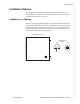
Installation Options Installation Options The 12000E BLC is designed for installation in a Restricted Access area where admittance is limited to trained and authorized service personel. It may be installed on a tabletop or in a rack. Installation on a Tabletop Insert the four provided rubber bumper screws into the mounting holes at the bottom of the 12000E chassis for surface grip and airflow.
Installing in a Rack 1 Using a Phillips screwdriver, attach the two provided rack mount brackets to the sides of the 12000E with eight of the ten provided bracket screws. There are seven position options for the rack brackets; position them as best suited to the space available for your chassis on the rack being utilized.
Installing Your Management Module 12000E Front View 1 2 3 4 5 6 7 8 12000E 9 10 11 12 U1 U2 05-17802 3 Check the rack for stability, ensuring that installation of the 12000E has not caused the rack to become top-heavy. Position and secure all connecting cables such that they will not become a tripping hazard or pull loose from the chassis. Installing Your Management Module A management module provides the functional control for the 12000E BLC; the BLC cannot function without one.
1 Select a slot for installation. The 12000E is a fourteen slot chassis: slots 1–12 are reserved for interface modules and slots U1–U2 are reserved for management modules. Although the 12000E is shipped with Port U1 open, your management module can be installed in either Port U1 or Port U2. Only one management module is required for operational purposes. However, two management modules may be installed if redundancy is desired: one in Slot U1 and one in Slot U2.
Installing Your Management Module 2 With the management module printed circuit board (PCB) facing right and the management module model name upright, align the upper and lower edges of the PCB with the slot module guides. 1 2 3 4 5 6 7 8 12000E 9 10 11 12 U1 U2 Management Module MUM 05-17804 Slot Module Guides 3 Slide the management module firmly into the chassis. Tighten the fastening screws on the management module faceplate.
Installing Your Interface Module(s) Interface modules provide the subscriber connections for an 12000E; up to twelve interface modules may be installed in the 12000E (slots 1–12). There are a variety of models available for purchase; contact your sales representative for further information or visit www.zhone.com for a list of available products.
Powering Up Your 12000E 3 Slide the interface module firmly into the chassis. Tighten the fastening screws on the interface module faceplate. 1 2 3 4 5 6 7 8 12000E 9 10 11 12 U1 U2 PWR TIM MUM 05-17807 Fastening Screws Powering Up Your 12000E CAUTION: Turn your DC power source(s) OFF until you have completed connection of the 12000E as outlined in the following sections. Do not operate the 12000E without a ground connection.
Ground Connection Close-up 05-17809 2 Connect the ground wire to a frame ground. Ground wire connection can vary from location to location though typically all equipment in a Central Office is grounded to a common copper bus. 3 Select a terminal block. Either terminal block on the back of the 12000E may be used to power the chassis; only one terminal block is required for operational purposes. The two terminal blocks on the 12000E are independent feeds.
Powering Up Your 12000E 4 Using a Phillips screwdriver, remove the left-hand screw from the chosen terminal block (labeled "+" on the chassis). Slide the ring terminal of your positive power lead around the shaft of the screw and insert the screw into the same "+" terminal from which it was removed. DC Power Terminal Positive (+) Terminal 48 V 30A Positive Power Lead Ring Terminal 48 V 30A 05-17811 5 Remove the right-hand screw (labeled "–") from the same terminal block.
7 Verify the connection. Turn your power source(s) on. The PWR (power) LED on the interface module and management module faceplates will illuminate solid green to indicate the modules are receiving power.
Connecting Your Subscriber Lines Connecting Your Subscriber Lines No configuration is necessary for the interface module(s) installed in your 12000E to operate at default settings. However, if you wish to run your subscriber connections at settings other than the defaults, configure the interface module(s) prior to connection. Refer to the installation instructions for your particular interface module(s). The 12000E chassis supports ADSL, IDSL, SDSL and T1/E1 technologies.
2 Detach the hook-and-loop fastener strap from the female RJ21 connector port: lift the hook-and-loop fastener tab on the left and pull the strap open towards the right, leaving it looped under the right side of the connector frame. Femle RJ21 Connector A for Interface Module Slot 3 05-17816 3 Slide the male RJ21 connector of your interface cable underneath the hook-and-loop fastener, from the bottom, and press it firmly into the female RJ21 connector port on the chassis.
Connecting Your Subscriber Lines 05-17818 5 Verify the connection(s). The LK (Link) LED for each port being connected with a remote modem will illuminate solid or flashing green (depending on the interface module model) to indicate a connection has been established. Link up time between interface modules and remote modems can vary from one to five minutes depending on the quality, gauge and distance of the copper cable pair(s) being used.
Configuration and Management Although no configuration is necessary to run subscriber lines at the default settings, all 12000E parameter settings are software selectable via Command Line Interface (CLI), Simple Network Management Protocol (SNMP), or the Network Management System (NMS), depending upon the capabilities of the management module model installed in your chassis.
Fan Module Fan Module The 12000E fan module is installed horizontally above the interface module slots. It comes pre-installed and should not be removed unless it is being replaced. Fan functionality is indicated by a FAN LED on the management module (all models): no illumination or solid green illumination indicates all fans are currently functioning, solid amber illumination indicates one or more of the four fans are no longer functioning.
Specifications Table 2: Specifications Specification Criteria Environment Operating Temperature: –40° F to 149° F (–40° C to 65° C) Storage Temperature: –40° F to 158° F (–40° C to 70° C) Humidity: 5 % to 95 %, non-condensing Altitude: –200 ft to 16,500 ft (–60 m to 5,000 m) Physical 15.75" High x 17" Wide x 18" Deep (40 cm High x 43.2 cm Wide x 46 cm Deep) 47 lbs (21.
Important Safety Instructions 4 This product is to be installed only in a Restricted Access Location (dedicated equipment rooms, equipment closets or the like) in accordance with articles 110-16, 110-17 and 110-18 of the National Electrical Code, ANSI/NFPA 70. 5 This product is to be connected to a 48 VDC SELV supply source that is electrically isolated from the AC source. 6 The positive terminal of the 48 VDC source is to be reliably connected to earth.
— Do not use the telephone to report a gas leak in the vicinity of the leak. 13 The equipment is intended for installation in an environment that is free of dust and dirt. 14 When installed in the final configuration, the product must comply with the applicable Safety Standards and regulatory requirements of the country in which it is installed. If necessary, consult with the appropriate regulatory agencies and inspection authorities to ensure compliance.
Notice to Users of the Canadian Telephone Network Notice to Users of the Canadian Telephone Network NOTICE: This equipment meets the applicable Industry Canada Terminal Equipment Technical Specifications. This is confirmed by the registration number. The abbreviation IC before the registration number signifies that registration was performed based on a Declaration of Conformity indicating that Industry Canada technical specifications were met. It does not imply that Industry Canada approved the equipment.
Technical Support If you require assistance with the installation or operation of your product, or if you want to return a product for repair under warranty, contact GSS. The contact information is as follows: E-mail support@zhone.com Telephone (North America) 877-ZHONE20 Telephone (International) 510-777-7133 Internet www.zhone.