
User`s guide


3810Plus Installation
2-53980-A2-GB30-40 October 1998
Network Management
System Connection
For the 3810Plus modem, use the following procedure
to connect the modem to the network management system
interface:
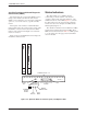
1. Insert the subminiature 4-position, 4-conductor
modular plug of the 3600 Hubbing Device
(Figure 2-3) into the jack labeled NMS
(Figure 2-2).
2. Connect the 3600 Hubbing Device to the network
management system.
Refer to the 3600 Hubbing Device, Feature Number
3600-F3-300, Installation Instructions for more
information. Installation for the 3810Plus modem is the
same as for the 3610 DSU.
3000HUBBING DEVICE
MODEL #3000-F3-300
8-Pin
Modular
Jacks
6 Inches
Overall
4-Pin
Modular
Plug
496-13775-03
8
1
Pin
Numbers
8
1
CC IN/DC OUT
CC OUT/DC IN
CC IN/DC OUT
Hubbing Device
CC OUT/DC IN
Figure 2-3. 3600 Hubbing Device
Modem Power-Up
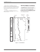
Once your modem is properly connected to the DTE,
dial and/or leased lines, and ac outlet, press the modem’s
rear panel power switch to the ON position. The modem
begins a power-up self-test. This test takes several
seconds to perform, and verifies the operation of most
hardware components within the modem. If successful,
the LCD displays Power On Selftst Passed and continues
to the Top-Level menu screen.
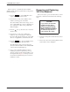
F1
Power On Selftst
Passed
F2
F3
If a failure occurs during the self-test, the LCD may
display Power On Selftst Failed for several seconds. The
LCD then may display the Top-Level menu screen with
the message Power on Fail appearing on the top line of
the LCD. Although a failure has occurred, the modem
may attempt to operate. If it does, you can activate a more
thorough self-test using the Test branch. Refer to
Chapter 7, Test Branch.