
User`s guide


3-13980-A2-GB30-40 October 1998
3811
Plus
Installation
Overview
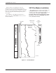
The carrier-mounted 3811Plus modem (Figure 3-1) is
capable of dial or 4-wire/2-wire leased-line operation and
resides in a COMSPHERE 3000 Series Carrier. The
faceplate of the 3811Plus has 16 LED status indicators for
displaying modem activity and an audio speaker jack for
the carrier’s optional speaker.
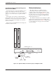
The 3811Plus modem’s backplate has two DTE edge
card connectors that mount into a connector plate located
on the rear of the carrier. This connector plate has two
DB-25-S connectors. One provides an RS-232D DTE
interface, and the other is unused. The 3811Plus derives
ac power from the COMSPHERE 3000 Series Carrier’s
backplane, which is a common bus to all devices installed
in the carrier. The user interface with any 3811Plus is the
shared diagnostic control panel (SDCP), an optional
feature similar to the DCPs on the 3810Plus. For a better
understanding of DCP operation, refer to Chapter 4, Front
Panel Operation.
The COMSPHERE 3000 Series Carrier has a total of
17 slots. The first slot, Slot 0, is reserved for the shared
diagnostic unit (SDU) while the remaining 16 slots can
house up to 16 3811Plus modems, or for mixed networks,
a combination of 3811Plus modems and other Paradyne
access products, such as Model 3611 data service units.
An SDU is a circuit card that provides SDCP and network
management interfaces to access products installed in the
carrier. SDUs are only required if a single SDCP is used
by multiple COMSPHERE 3000 Series Carriers in a
cabinet, or if a network management system (NMS) is
used.
For more details on the COMSPHERE 3000 Series
Carrier, refer to the COMSPHERE 3000 Series Carrier,
Installation Manual.
3811
Plus
Modem Package
After opening the modem’s package, check for damage
and verify that the following items are present:
• 3811Plus modem
• Rear connector plate with DB-25-P edge card
connector
If any hardware components are damaged, notify your
service representative. Return equipment using procedures
described in the Government Requirements and
Equipment Return section near the beginning of this book.
Customer-Supplied Equipment
The following customer-supplied equipment may be
required for the installation of a 3811Plus modem:
• A COMSPHERE 3000 Series Carrier.
• A Shared Diagnostic Unit (SDU, required for
network management applications and multiple
carriers).
• Two 50-pin mass termination cables, one Network
Interface Module (NIM) for modems installed in
Slots 1–8, and one NIM for modems installed in
Slots 9–16 (required for dial-line applications).
• One of the following dial or leased network
interfaces:
— 50-pin to modular cable (RJ11C) for dial
permissive applications
— 50-pin to modular cable (JM8) for leased line
applications
• One 6-position to 6-position modular cord (required
for network management applications).
• A Shared Diagnostic Control Panel (SDCP).
3