
Installation manual


T1 Auxiliary Backplane
3-53000-A2-GA31-F0 March 2001
T1 CSU and T1 DSU/CSU
Network Interface
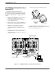
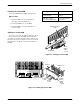
The T1 auxiliary backplane, installed over either
Slots 1–8 or Slots 9–16 at the back of a 3000 Series
Carrier, provides the interfaces for T1 CSUs and/or
T1 DSU/CSUs to a T1 network.
The T1 CSU and T1 DSU/CSU network interface is
provided by one 50-pin connector on the T1 auxiliary
backplane on the back of the carrier. This connector
serves eight contiguous slots in the carrier: either
Slots 1–8 or Slots 9–16.
Depending on your configuration, use one of the
following schemes for the T1 CSU and T1 DSU/CSU
network interface.
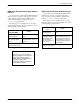
If a 50-pin cable is . . .
Then . . .
Attached to a 66A punchdown
block
Hardwire the circuits
to the block.
Plugged into a feature
3100-F1-930 adapter cable,
which provides 8 non-keyed
modular plugs using Pins 1, 2,
4, and 5
Connect the T1 CSU
or T1 DSU/CSU to a
standard network
interface.
The network interface cable can be connected to
additional network interface cables, up to the maximum of
100 feet.
To connect the T1 CSU and T1 DSU/CSU network
interface:
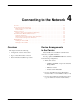
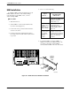
" Procedure
1. Connect the network cable to the carrier.
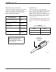
2. Choose one of the following:
If you are
using . . .
Then . . .
The Telco
connector cable
Install the black plastic
network cable retainer.
A straight-in
connector
Use a small screwdriver to
engage and tighten the
screws.
3. Connect the individual cables with 8-pin modular
plugs into the adapter for each T1 line.
T1 CSU DTE Port
The T1 auxiliary backplane provides a DB15 socket
connector for each CSU. The DTE cable is normally
supplied by the DTE vendor. For more information, see
the ACCULINK 3150 and 3151 CSU Operator’s Guide.
T1 DSU/CSU DTE Ports
The T1 auxiliary backplane provides connections for a
DSX-1 drop/insert port and two synchronous data ports
for each DSU/CSU.
The drop/insert interface is a DB15 socket connector.
The synchronous ports may be used for the following
interfaces:
• EIA-530-A
• V.35
• RS-449
• X.21
The interface is determined by the cable and adapter
used, and the Port Type configuration option selected. See
Appendix D, Equipment List, and the Port Configuration
Options table in the ACCULINK 3160, 3161, 3164, and
3165 DSU/CSU Operator’s Guide.
V.35 Adapters
In applications where V.35 adapters are used on both
data ports, do not use a short V.35 adapter plug for both
ports. Use a V.35 adapter cable (feature 3100-F1-570) for
the second DTE port. Otherwise it may be impossible to
fasten the connectors.
SNMP LAN Adapter
Connectivity
The T1 DSU/CSU can be configured to provide SNMP
connectivity to an NMS using an external LAN (Local
Area Network) adapter. The SNMP LAN Adapter is an
interface device that allows SNMP managed devices to be
connected to Ethernet or Token Ring LANs. For further
details, refer to:
• Appendix D, Equipment List.
• The ACCULINK 3160, 3161, 3164, and 3165
DSU/CSU Operator’s Guide.