
Installation manual


Connecting to the Network
4-73000-A2-GA31-F0 March 2001
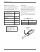
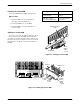
Installing the 24-Port NIM
The 24-port NIM includes a NIM cover and cable.
" Procedure
1. Fasten the NIM to the carrier with the four
standoffs provided. See Figure 4-4.
2. Position the NIM cover over the NIM.
3. Fasten the NIM cover in place with the four
screws provided.
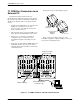
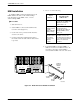
Cabling the 24-Port NIM
Connect one end of the short ribbon cable to the 50-pin
connector at the bottom of the NIM. Connect the other
end to P21 (on the right side of the carrier) or P22 (on the
left side of the carrier). See Figure 4-3. Connect a network
interface cable to the 50-pin connector in the middle of
the NIM.
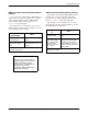
If a 50-pin cable is . . .
Then . . .
Attached to a 66A
punchdown block
Hardwire the circuits to
the block.
Plugged into a feature
3821-F1-500 adapter cable
Connect the 24 RJ11C
6-pin cables.
496-14798a
Network Interface
Cable
P21 or P22
Short
Ribbon
Cable
Figure 4-3. Cabling the 24-Port NIM
P26 P25
P24
P23
P20 P19
J2 P22
J1
P21
496-14854a
To P23
or P25
To P24
or P26
Network
Interface
Module
(NIM)
NIM Cover
Standoff
Figure 4-4. Installing the 24-Port NIM