COMSPHERE 3821PLUS MODEM USER’S GUIDE Document No.
COMSPHERE 3821Plus Modem COMSPHERE 3821Plus Modem User’s Guide 3821-A2-GB20-40 5th Edition (January 1999) Changes and enhancements to the product and to the information herein will be documented and issued as a new release or a limited revision of this manual. For the 3821Plus modem the USOC for Permissive mode is RJ21X. The Canadian equivalent to the USOC is CA21A. For single line connection to an analog private line, an adapter cable should be used to facilitate connection to a JM8 jack.
Safety Instructions ! Important Safety Instructions 1. Read and follow all warning notices and instructions marked on the product or included in the manual. 2. Slots and openings in the cabinet are provided for ventilation. To ensure reliable operation of the product and to protect it from overheating, these slots and openings must not be blocked or covered. 3. Do not allow anything to rest on the power cord and do not locate the product where persons will walk on the power cord. 4.
COMSPHERE 3821Plus Modem Notices
Safety Instructions Government Requirements and Equipment Return Certain governments require that instructions pertaining to modem connection to the public switched telephone network be included in the installation and operation manual. Specific instructions are listed in the following sections. United States Notice to Users of the Public Switched Telephone Network 1. This equipment complies with Part 68 of the FCC rules.
COMSPHERE 3821Plus Modem Canada Notice to Users of the Canadian Public Switched Telephone Network The Canadian Department of Communications label identifies certified equipment. This certification means that the equipment meets certain telecommunications network protective, operational and safety requirements. The Department does not guarantee the equipment will operate to the user’s satisfaction.
Safety Instructions This modem is suitable for connection to BT circuits with signalling at a nominal frequency of 2280 Hz and may be connected to multipoint or point-to-point circuits. The apparatus does not require signalling or otherwise use the frequency range 0 –200 Hz. No d.c. interaction is intended between the modem and the telephone network. This apparatus may be directly connected to a speechband circuit or connected to a relevant branch system for speechband circuits.
COMSPHERE 3821Plus Modem This page intentionally left blank.
Table of Contents Preface Objectives and Reader Assumptions . . . . . . . . . . . . . . . . . . . . . . . . . How to Use This Manual . . . . . . . . . . . . . . . . . . . . . . . . . . . . . . . . . . Related Documents . . . . . . . . . . . . . . . . . . . . . . . . . . . . . . . . . . . . . . v v vi 1. Introduction Overview . . . . . . . . . . . . . . . . . . . . . . . . . . . . . . . . . . . . . . . . . . . . . . Features . . . . . . . . . . . . . . . . . . . . . . . . . . . . . . . . . . . . . . . . .
COMSPHERE 3821Plus Modem 4. AT Commands and S-Registers Overview . . . . . . . . . . . . . . . . . . . . . . . . . . . . . . . . . . . . . . . . . . . . . . Operating Modes . . . . . . . . . . . . . . . . . . . . . . . . . . . . . . . . . . . . . . . . Command Guidelines . . . . . . . . . . . . . . . . . . . . . . . . . . . . . . . . . . . . . AT Command List . . . . . . . . . . . . . . . . . . . . . . . . . . . . . . . . . . . . . . . S-Register List . . . . . . . . . . . . . . . . . . . . . . . . . . . .
Table of Contents D. Technical Specifications E. Pin Assignments EIA-232-E Pin Assignments . . . . . . . . . . . . . . . . . . . . . . . . . . . . . . . JM8 to RJ11 Crossover Cable . . . . . . . . . . . . . . . . . . . . . . . . . . . . . . NIM Cable Pin Assignments . . . . . . . . . . . . . . . . . . . . . . . . . . . . . . . E-1 E-2 E-3 F. ITU-T V.25bis Dialing Commands and Responses Overview . . . . . . . . . . . . . . . . . . . . . . . . . . . . . . . . . . . . . . . . . . . . . .
COMSPHERE 3821Plus Modem This page intentionally left blank.
Preface Objectives and Reader Assumptions Chapter 5 provides general information about fax modem operation. This guide describes how to install the 3821Plus circuit card and operate the 3821Plus modem. It is intended for all users of the 3821Plus modem. Each 3821Plus card comprises three modems. In general this guide refers to the 3821Plus modem with regard to operation and the 3821Plus card with regard to installation.
COMSPHERE 3821Plus Modem Related Documents vi Contact your sales or service representative to order additional product documentation. Paradyne documents are also available on the World Wide Web at: 3000-A2-GA31 COMSPHERE 3000 Series Carrier Installation Manual 3980-A2-GB30 COMSPHERE 3800Plus Modems, User’s Guide 6700-A2-GY31 COMSPHERE 6700 Series Network Management System, User’s Guide 6800-A2-GE26 COMSPHERE 6800 Series Network Management System, User’s/System Administrator’s Guide http://www.
Introduction Overview . . . . . . . . . . . . . . . . . . . . . . . . . . . . . . . . . . . . . . . . . . . . . . . . . . . . . . . . . . . . . . . . . . . . . . . . . . Features . . . . . . . . . . . . . . . . . . . . . . . . . . . . . . . . . . . . . . . . . . . . . . . . . . . . . . . . . . . . . . . . . . . . . . . . . . . Status Indicators . . . . . . . . . . . . . . . . . . . . . . . . . . . . . . . . . . . . . . . . . . . . . . . . . . . . . . . . . . . . . . . . . . . . SDCP Operation . . . . . . .
COMSPHERE 3821Plus Modem • Storage of up to 10 telephone numbers to directory locations. Status Indicators • Originate Security and three Answer Security modes. • Callback Security with telephone directory index or telephone number. The status indicators on a 3821Plus circuit card continuously provide information on the modem’s operating condition. The status indicators for the 3821Plus card are located on its faceplate, the SDCP, and the Shared Diagnostic Unit (SDU) faceplate (Figure 1-1).
Introduction Table 1-1 3821Plus LEDs Label ALRM A Color red Indicates Alarm A ON: Modem A has detected a problem with its operation. ALRM B red Alarm B ON: Modem B has detected a problem with its operation. ALRM C red Alarm C ON: Modem C has detected a problem with its operation. Mod A green Modem A ON: The status of Modem A is reflected by the TXD, RXD, CD, RI, DTR, and OH LEDs. If the Front Panel LED is ON, Modem A is connected to the SDCP.
COMSPHERE 3821Plus Modem SDCP Operation Key The SDCP on the 3000 Series Carrier is the user interface to all functions used to configure and control the 3821Plus modem. This interface includes the status LEDs, and a two-line, 32-character Liquid Crystal Display (LCD) and keypad (Figure 1-2). MOVES UP ONE LEVEL FROM CURRENT DISPLAY HIDDEN CHOICE INDICATOR LCD TOP LINE The key returns you to the Top-Level menu display from anywhere in the menu tree.
3821Plus Modem Installation Overview . . . . . . . . . . . . . . . . . . . . . . . . . . . . . . . . . . . . . . . . . . . . . . . . . . . . . . . . . . . . . . . . . . . . . . . . . . 3821Plus Installation . . . . . . . . . . . . . . . . . . . . . . . . . . . . . . . . . . . . . . . . . . . . . . . . . . . . . . . . . . . . . . . . Install the Carrier . . . . . . . . . . . . . . . . . . . . . . . . . . . . . . . . . . . . . . . . . . . . . . . . . . . . . . . . . . . . . . . . . Install the NIM . . . . . .
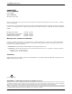
COMSPHERE 3821Plus Modem STANDOFF NIM COVER P24 P26 J2 P25 P23 P20 P19 P22 J1 P21 TO P23 OR P25 TO P24 OR P26 NETWORK INTERFACE MODULE (NIM) 495-14854 Figure 2-1. Installing the NIM Install the NIM A NIM can be installed on the left or right side of the back of the 3000 Series Carrier. A 2-wire leased line connection to a JM8 interface requires a 6-position to 8-position crossover cable. See Appendix E. " Procedure 1.
3821Plus Modem Installation " Procedure Attach the DTE Interface Assembly The eight-slot DTE interface assembly can be mounted on the left or the right side of the carrier. If you are installing only one interface assembly, it must be mounted on the same side you installed the NIM. 1. Feed the eight tabs at the bottom of the DTE interface assembly into the slots on the left or right side of the carrier. 2. Insert the screws provided, but do not completely tighten them. See Figure 2-3.
COMSPHERE 3821Plus Modem " Procedure Install the Circuit Card 1. Turn the circuit pack lock until it is vertical, locking the 3821Plus card in place. See Figure 2-5. Slide the 3821Plus card into its slot in the 3000 Series Carrier. Press firmly until the back edge of the card seats in the socket of the DTE interface assembly. 2. When all cards are installed and locked in place, tighten the screws on the DTE interface assembly.
3821Plus Modem Installation Install Communications Software A computer commands and controls a modem through communications software. This software uses the AT command set to send instructions to the modem. A dumb asynchronous terminal, however, does not require this software since it can directly send AT commands. The preset configuration gives you a “head start” in getting your modem operating and reduces the amount of time required to configure your modem.
COMSPHERE 3821Plus Modem Selecting Configurations Using AT Commands 5. Press the key until the appropriate factory preset appears on the LCD, and press the corresponding function key to select your choice. 6. Choose Function appears and displays the Edit and Save functions. 7. Press the F3 key (Save) to save the new factory preset configuration to one of three configuration areas, Active (Saved), Customer 1, or Customer 2. (These three configuration areas are nonvolatile memory locations.
3821Plus Modem Installation To change a factory template using AT commands, perform the following steps (for more information on changing factory templates using AT commands, refer to Chapter 4, AT Commands and S-Registers). " Procedure The &V (View) command can be used to display the configuration options in effect.
COMSPHERE 3821Plus Modem This page intentionally left blank.
SDCP Menus Menu Structure . . . . . . . . . . . . . . . . . . . . . . . . . . . . . . . . . . . . . . . . . . . . . . . . . . . . . . . . . . . . . . . . . . . . . Modem Status Messages . . . . . . . . . . . . . . . . . . . . . . . . . . . . . . . . . . . . . . . . . . . . . . . . . . . . . . . . . . . . . . Modem Select Branch . . . . . . . . . . . . . . . . . . . . . . . . . . . . . . . . . . . . . . . . . . . . . . . . . . . . . . . . . . . . . . . . Call Setup Branch . . . . . . . . . . . . . . . . . .
COMSPHERE 3821Plus Modem Menu Structure Status Used to monitor the current status of the VF line and DTE interface as well as view the identity of the modem. Test Used to begin and end various modem tests. Configure Used to change and save the modem’s configuration options. Control Used to control the modem’s hardware and software functions. Remote Used to access and control a remote 3800Plus modem. See Chapter 6, Remote Access.
SDCP Menus Modem Status Messages Access to all menu tree branches from the SDCP begins at the Top-Level menu, the head of the menu hierarchy. The LCD’s top line identifies the modem status, as listed in Table 3-1, while the bottom line displays the main menu tree branches and operational and dial access security messages, as listed in Table 3-2 and Table 3-3. Messages listed in Table 3-2 are common operational messages that occur during modem operation.
COMSPHERE 3821Plus Modem Table 3-1 (2 of 3) Top-Level Menu Status Normal Call Setup Messages Indicates Off Hook The modem is off-hook and waiting to dial a telephone number. Dialing The remote modem is being dialed. Training The modem is training or retraining. EC Negotiating The local and remote modems are negotiating the highest possible level of error control compatible between both modems. Once a level is selected, this LCD message disappears.
SDCP Menus Table 3-1 (3 of 3) Top-Level Menu Status Call Disconnect Messages, continued Indicates LongSpace Disc The modem has disconnected due to the detection of a long space. NoData Disc The modem has disconnected due to a lack of transmitted and received data. Disconnecting The modem has begun the disconnect sequence. Rmt Cmnded Disc The modem has disconnected due to a V.32 or V.34 Cleardown received from the remote modem.
COMSPHERE 3821Plus Modem Table 3-3 Dial Access Security Messages Dial Access Security Messages Indicates Get VF PsWd The answering modem is waiting for the originating caller to transmit a VF password. Get DTE PsWd The answering modem is waiting to receive a valid DTE password from the remote DTE. VF PsWd Timeout The modem did not finish answering a call (disconnected) because the allowed time limit was exceeded before the modem received a VF password from the originating dialer.
SDCP Menus Modem Select Branch If the modem is operating with V.34 modulation, the following screen appears. The Modem Select branch is the top level of the menu structure. The modem selections are displayed when the SDCP is first connected to a 3800Plus card (using the Select key on the SDCP). xxxx yyyyy zz abbb cdd ee ffff F1 Idle : 33.6 > MDMA mdmb mdmc F1 F2 F2 > F3 The V.34 modulation Quick Configuration information appears on the LCD’s top line.
COMSPHERE 3821Plus Modem ffff Displays the modem’s modulation scheme as shown below: V34 indicates V.34 family modulation. V32t indicates V.32terbo modulation. V32b indicates V.32bis modulation. V32 indicates V.32 modulation. V22b indicates V.22bis modulation. V27b indicates V.27bis modulation. V33 indicates V.33 modulation. V29 indicates V.29 modulation. V22 indicates V.22 modulation. V23 indicates V.23 modulation. V21 indicates V.21 modulation. 212A indicates Bell 212A modulation.
SDCP Menus Call Setup Branch The Call Setup branch of the Top-Level menu allows you to dial, disconnect, and answer telephone calls. It also allows you to create and store up to 10 telephone numbers to directory locations. Four different functions can appear under Call Setup: • Dial • Disconnect If the connection is successful, the modem is online and one of the Normal Operation status messages appears on the LCD.
COMSPHERE 3821Plus Modem Change Directory Change Directory allows you to enter or modify telephone numbers. The modem has nonvolatile memory locations that allow you to store up to 10 telephone numbers. Each directory location can accept up to 40 characters; this includes the telephone number and dial command modifiers. Any telephone number dialed using the SDCP Dial command must appear in a directory location. To access Change Directory from the Call Setup branch, make the following selections: 1.
SDCP Menus Status Branch displayed are approximations that may be affected by the combination of impairments on the line. The Status branch of the Top-Level menu allows you to view the current status of the dial or leased-line connection, the DTE interface, and the identity (for example, serial number and model number) of your equipment. The selections under Status are: NOTE SigQual, NearEcho, FarEcho, FarEchDel, and EchoFreqOff values appear only for V.34, V.32terbo, V.32bis, and V.32 modulations.
COMSPHERE 3821Plus Modem Identity 2. Select DTE. The activity and state of the modem’s DTE signal appear on the LCD’s bottom line. Identity displays the modem’s serial number, model number, firmware revision level, hardware part number and firmware part number. Retrieval of this information is useful if you are purchasing additional or replacement modems and/or making firmware upgrades. 3. Press the key to scroll other signals into view.
SDCP Menus Abort To exit this function and remain in the Status branch, key. To exit and return to the Top-Level press the key. menu, press the Abort ends any test that is in progress and brings the modem back to the normal mode of operation. Confirmation is provided by the Command Complete message. Test Branch The Test branch of the Top-Level menu allows you to initiate various modem tests.
COMSPHERE 3821Plus Modem If the Test Timeout configuration option is enabled, Test Timeout appears at the conclusion of the test. If it is disabled, the test operates until aborted. For more information on the Test Timeout configuration option, refer to Table 3-10 in this chapter. To access Loc Digital Loop from the Test branch, key until Loc Digital Loop appears. Press press the any function key to start this test. The message Started appears on the LCD and the Test LED lights.
SDCP Menus To exit this function and remain in the Test branch, key. To exit and return to the Top-Level press the key. menu, press the and, if ETC is installed, Cellular (Mobile), and Cellular (PSTN). These sets contain the most commonly used configuration options for modems installed in these hardware environments, and give you a head start in configuring your modem.
COMSPHERE 3821Plus Modem (Modem Status) MDMA mdmb mdmc Status Call_Setup Test Idle : 33.6 Test Control Remote Security F1 Configure F2 F3 Select Configure from the Top-Level menu.
SDCP Menus Scroll to and select the Misc configuration options group. To save the new password to a configuration area, make the following selections. RemAccssPasswrd NxtąĄ°12345678 Edit StrapGroup < Test Misc F1 F2 F3 F1 Press the StrapsWhenDisc > Nxt No_Change F1 F2 F2 F3 key to scroll up (twice). Choose Function Edit Save F3 F1 F2 F3 Select Nxt until RemAccssPasswrd appears. Select Save.
COMSPHERE 3821Plus Modem • The key causes you to exit the Configure branch and return to the Top-Level menu. If any changes are made to configuration options, the SDCP allows you to save these changes to either the Active (Saved), Customer 1, or Customer 2 configuration areas. • The LCD. and NOTE In some countries, the range of allowable values of some configuration options is restricted. The modem will accept any selection, but it will set the configuration option to the closest allowable value.
SDCP Menus Table 3-4 (1 of 6) DTE Interface Configuration Options Async/Sync Mode: Async Nxt Async Sync Asynchronous/Synchronous Mode. Determines whether the modem operates in Asynchronous mode or Synchronous mode. If the AT command set is enabled and this configuration option is set for Sync, then the modem operates in Async mode when offline. For Async Dial and UNIX Dial, Async is the factory default. For Sync Dial and Sync Leased, Sync is the factory default. AT command equivalents are &Mn and &Qn.
COMSPHERE 3821Plus Modem Table 3-4 (2 of 6) DTE Interface Configuration Options Asyn Parity Bit: None Nxt None Even Odd Mark Space This configuration option only appears if Async/Sync Mode is configured for Async or DTE Dialer Type is enabled. Asynchronous Parity Bit. Determines type of asynchronous parity bit. The parity of the DTE must match the parity of the modem. Parity options include None, Even, Odd, Mark, or Space. None – No parity bit is used.
SDCP Menus Table 3-4 (3 of 6) DTE Interface Configuration Options DTR Action: Ignore Nxt Stndrd_RS232 Ignore CntrlsOnHook Off=ReloadStrp Off=CmdMode Data Terminal Ready Action. DTR is a signal from the DTE to the modem indicating that the DTE is connected and ready for operation. Standard RS232 – Allows the DTE to control DTR to the modem as specified in RS-232D and ITU-T V.24 specifications. If this signal is not present, the modem will not answer or dial. Ignore – Modem assumes DTR is always ON.
COMSPHERE 3821Plus Modem Table 3-4 (4 of 6) DTE Interface Configuration Options RTS Action: Ignore Nxt Ignore Stndrd_RS232 Sim_Cntl_Car Request-to-Send Action. RTS is a signal from the DTE to the modem indicating the DTE has data to send to the modem. Ignore – Modem assumes RTS is always ON. Use this selection when the DTE does not provide RTS to the modem. Standard RS232 – Allows the DTE to control RTS to the modem in normal RS-232D operation. RTS must be ON for the DTE to transmit to the modem.
SDCP Menus Table 3-4 (5 of 6) DTE Interface Configuration Options RTS/CTS Delay: 0 msec Nxt 0msec 10msec 50msec 150msec 600msec Request-to-Send/Clear-to-Send Delay. RTS/CTS Delay sets the delay time between the modem receiving RTS from the DTE and the modem sending CTS to the DTE. This delay is only valid in Async Direct mode and synchronous applications when it is necessary to have a short delay between the time the DTE raises RTS and the time the modem presents CTS to allow the DTE to send data.
COMSPHERE 3821Plus Modem Table 3-4 (6 of 6) DTE Interface Configuration Options TX Clock Source: Internal Nxt Internal External RXC_Loop This configuration option only appears when Async/Sync Mode is configured for Sync. Transmit Clock Source. Determines the source of timing for synchronous data transmitted from the DTE. Internal – The transmit data’s clock source is derived from the modem’s internal clock and output on Pin 15 (TXC) of the RS-232D interface.
SDCP Menus DTE Dialer Table 3-5 shows each DTE Dialer configuration option as it appears on the LCD. The DTE Dialer configuration options establish the DTE-to-modem protocol for call establishment and control. Table 3-5 (1 of 5) DTE Dialer Configuration Options DTE Dialer Type: AT Nxt AT Disable V25bis_Async V25bis_Bsync V25bis_HDLC DTR=Direct1 AT&T_Exclusv Data Terminal Equipment Dialer Type. Identifies to the modem the type of dialing method and protocol used by the DTE.
COMSPHERE 3821Plus Modem Table 3-5 (2 of 5) DTE Dialer Configuration Options *Escape GuardTim: 1sec Nxt 1sec 200msec 400msec 600msec 800msec 2sec Escape Guard Time. Determines the length of the required pause before and after the escape sequence is issued. The guard time prevents the modem from interpreting data as the escape sequence characters. The factory default is 1 second. AT command equivalent is S-register S12=n. *BreakForceEscap: Disable Nxt Disable Enable Break Forces Escape.
SDCP Menus Table 3-5 (3 of 5) DTE Dialer Configuration Options *Linefeed Char: 010 ASCI Nxt ↑ 010 ASCI Line Feed Character. Sets the character used to perform a line feed in Command mode for responses from the modem. The factory default is 010 (ASCII line feed character). AT command equivalent is S-register S4=n. *Result Codes: Enable Nxt Enable Disable EnableInOrig Result Codes.
COMSPHERE 3821Plus Modem Table 3-5 (4 of 5) DTE Dialer Configuration Options *ResultCode Form: Words Nxt Words Numbers (1) Numbers (2) Result Codes Format. Controls whether or not result codes appear as words or as numeric codes. Some DTEs do not recognize result codes as words; therefore, numbers are required. The Numbers (2) format is required for some modem pooling applications. (For a list of result codes, refer to Appendix B.) The factory default is Words. AT command equivalent is Vn.
SDCP Menus Table 3-5 (5 of 5) DTE Dialer Configuration Options V25bis IdleFill: Mark Nxt Mark Flag V.25bis Idle Fill. Determines whether a mark or flag is used as an idle fill character for the DTE. The modem responds to the DTE using the same idle fill. NOTE: This configuration option only appears if DTE Dialer is configured for V.25bis HDLC or V25bis Bisync. The factory default is Mark. AT command equivalent is S-register S63=n. V.25b NewLineChr: CR+LF Nxt CR+LF CR LF V.25bis New Line Character.
COMSPHERE 3821Plus Modem Line Dialer Table 3-6 shows each Line Dialer configuration option as it appears on the LCD. The Line Dialer configuration options establish parameters used by the modem to answer or originate calls. Table 3-6 (1 of 4) Line Dialer Configuration Options AutoAnswerRing#: 1 Nxt 1 Disable 2 4 6 8 10 Auto-Answer Ring Count. Determines the number of rings necessary before the answering modem answers an incoming call.
SDCP Menus Table 3-6 (2 of 4) Line Dialer Configuration Options BusyTone Detect: Enable Nxt Enable Disable Busy Tone Detect. Sets the modem to monitor for Busy Tone (Enable) or ignore Busy Tone (Disable). This configuration option is normally enabled; however, if the modem receives false busy tones, this configuration option can be disabled and the modem ignores all busy tones. The factory default is Enable. AT command equivalent is Xn. ‘‘,” Pause Time: 2sec Nxt 2sec 4sec 6sec 8sec 10sec 20sec Pause Time.
COMSPHERE 3821Plus Modem Table 3-6 (3 of 4) Line Dialer Configuration Options Long Space Disc: Enable Nxt Enable Disable Long Space Disconnect. Determines the modem’s response to a continuous spacing condition sent from the remote modem when it goes on-hook. Issuing a long space is one method of disconnecting a call. NOTE: This configuration option is ignored when the modem operates in Synchronous mode or Dial Backup mode. Enable – Modem disconnects if it receives a continuous space from the DTE.
SDCP Menus Table 3-6 (4 of 4) Line Dialer Configuration Options NoDataDiscTrig: TXD and RXD Nxt TXD and RXD TXD Only RXD Only TXD or RXD No Data Disconnect Trigger Signal. Works in conjunction with No Data Disconnect (\T), and determines whether Pin 2 (transmit data) or Pin 3 (receive data) of the modem’s RS-232 serial interface is monitored so that the modem can disconnect the call if there is no activity for a certain period of time.
COMSPHERE 3821Plus Modem Dial Line The Dial Line configuration options are used to configure the modem for operation over dial lines. The Dial Line configuration group does not appear if the modem is configured with the Sync Leased factory preset template, or if the &L1, &L2, &L3, or &L4 command is entered. Table 3-7 shows each Dial Line configuration option as it appears on the LCD.
SDCP Menus Table 3-7 (2 of 3) Dial Line Configuration Options Automode: Enable Nxt Enable Disable System 85 Automode. Allows the modem to automatically detect the remote modem’s modulation. Enable – The modem automatically adapts to the modulation scheme and line rate of the remote modem, and the VF line condition. However, the maximum data rate the modem uses is determined by the Dial Line Rate configuration option. Bell 103J protocol is used for data rates of 0–300 bps.
COMSPHERE 3821Plus Modem Table 3-7 (3 of 3) Dial Line Configuration Options V22b Guard Tone: Disable Nxt Disable 550Hz 1800Hz V.22bis Guard Tone. Determines whether the V.22bis guard tone is disabled, set to 550 Hz, or set to 1800 Hz. Disable – No guard tone. 550 Hz or 1800 Hz – When the modem is in Answer mode, it transmits the guard tone at this frequency. The factory default is Disable. NOTE: The default and permitted settings of this option are country-dependent. See Appendix H.
SDCP Menus Leased Line Table 3-8 shows each Leased Line configuration option as it appears on the LCD. The Leased Line configuration options are used to configure the modem for operation over leased lines. The Leased Line configuration group only appears if the modem is configured with the Sync Leased factory preset template, or if the &L1, &L2, &L3, or &L4 command is entered. Table 3-8 (1 of 2) Leased Line Configuration Options Leased Mode: 2WLL-Orig Nxt 2WLL-Orig 2WLL-Ans Leased Mode.
COMSPHERE 3821Plus Modem Table 3-8 (2 of 2) Leased Line Configuration Options Autorate: Enable Nxt Enable Disable Autorate. The modems adapt to VF line condition and connect at the optimum rate during initial line establishment. Once connected, the modem automatically lowers the line rate if line conditions become impaired. When line conditions improve, the modem automatically shifts up to the highest data rate the line can support. This autorating only occurs between 4800 bps and 19,200 bps during V.
SDCP Menus V.42/MNP/Buffer V.42/MNP/Buffer configuration options determine the type of error correction and flow control used by the modems and attached DTEs. Some choices within this group may not appear depending upon how previous configuration options have been selected. If the Async/Sync Mode configuration option is set for synchronous operation (see DTE Interface configuration options group), then the V.42/MNP/Buffer group does not appear on the LCD.
COMSPHERE 3821Plus Modem Table 3-9 (2 of 5) V.42/MNP/Buffer Configuration Options V42bis Compress: Enable Nxt Enable Disable This configuration option only appears if Async/Sync Mode is configured for Async and the Error Control Mode configuration option is set for V42/MNPorBfr or V42/MNPorDsc. V.42bis Compression. Enables or disables V.42bis data compression. Enable – Data compression operates in both the transmit and receive directions. This is the recommended setting for all applications. Disable – V.
SDCP Menus Table 3-9 (3 of 5) V.42/MNP/Buffer Configuration Options Flw Cntl of DTE: CTS_to_DTE Nxt CTS_to_DTE Disable XON/XOFF This configuration option only appears if Async/Sync Mode is configured for Async. Flow Control of DTE. Determines how the modem controls the flow of data from the DTE. CTS to DTE – Method of flow control in which the modem raises and lowers its CTS interface lead to indicate when the DTE should start and stop sending data.
COMSPHERE 3821Plus Modem Table 3-9 (4 of 5) V.42/MNP/Buffer Configuration Options Mdm/Mdm FlowCtl: Disable Nxt Disable Enable This configuration option only appears if Async/Sync Mode is configured for Async and the Flow Control configuration option is configured for XON/XOFF. Modem-to-Modem Flow Control. If a modem’s buffers begin to fill due to data it is receiving from the remote modem, but is not passing on to the DTE, it can issue XON/XOFF flow control characters to the remote modem.
SDCP Menus Table 3-9 (5 of 5) V.42/MNP/Buffer Configuration Options TXBuffDiscDelay: 10sec Nxt 10sec Disable 60sec This configuration option only appears when Async/Sync Mode is configured for Async, and Error Control Mode is not configured for DirectMode. Transmit Buffer Disconnect Delay. Determines how long the modem continues to transmit data stored in its Transmit buffer when the modem is commanded to disconnect by a locally attached DTE.
COMSPHERE 3821Plus Modem Test Table 3-10 shows each Test configuration option as it appears on the LCD. The Test configuration options determine specifics, such as the duration of a test, for the various diagnostic tests available to the modem. Table 3-10 Test Configuration Options Test Timeout: Disable Nxt Disable 30sec 60sec 240sec Test Time-out. Determines how long a test runs before aborting. Disable – Allows a test to run indefinitely.
SDCP Menus Misc Table 3-11 shows each Misc (Miscellaneous) configuration option as it appears on the LCD. The Miscellaneous configuration options determine specifics for various functions, including network management parameters and remote modem access. Table 3-11 (1 of 2) Miscellaneous Configuration Options StrapsWhenDisc: No_Change Nxt No_Change Reload RelodNoATChg Straps When Disconnected.
COMSPHERE 3821Plus Modem Table 3-11 (2 of 2) Miscellaneous Configuration Options NetMngmtAddress: 256 Nxt 256 Network Management Address. Determines the address used when accessing a locally attached modem from the 6700 Series NMS. This configuration option is ignored by remote modems. Address values range from 001 to 256. The factory default templates do not affect Network Management Address. AT command equivalent is S-register S75=n.
SDCP Menus Security Configuration Options Make Busy or Remove Make Busy The Security configuration options group is described in Chapter 7, Security. The Make Busy function is available only on 3821-B1 models. Control Branch The Make Busy function forces the modem off-hook so it cannot answer a call. This is often used with PBX systems to permit the busy out of a PBX port for rotary or hunt groups.
COMSPHERE 3821Plus Modem Download Code However, to continue with the transfer, press the key to display the Reprogram Remote selection. The Download Code function allows firmware to be loaded into a modem from another modem or from a DTE. WARNING Pressing any function key now begins the transfer to the remote modem. This process takes the communications link out of service for several minutes depending upon the data rate of the link (28,800 bps = 5 minutes).
SDCP Menus Automatic Firmware Download Download Failure New releases may be available for the 3821Plus modem. The latest 3821Plus firmware is avaiable at no charge from the Automatic Firmware Download Center. Refer to page A in the front of this document for contact information. To download the firmware, your modem must be configured for dialing. Save your modem’s current configuration to the Customer 1 or Customer 2 memory area, and load the Async Dial factory template.
COMSPHERE 3821Plus Modem This page intentionally left blank.
AT Commands and S-Registers Overview . . . . . . . . . . . . . . . . . . . . . . . . . . . . . . . . . . . . . . . . . . . . . . . . . . . . . . . . . . . . . . . . . . . . . . . . . . Operating Modes . . . . . . . . . . . . . . . . . . . . . . . . . . . . . . . . . . . . . . . . . . . . . . . . . . . . . . . . . . . . . . . . . . . . Switching Between Data Mode and Online Command Mode . . . . . . . . . . . . . . . . . . . . . . . . . . . . . . Escape Sequence and Escape Guard Time . . . . . . . . . . . . .
COMSPHERE 3821Plus Modem • Commands shown with the suffix n have several options associated with them. For example, in the Ln command, L1 sets the speaker volume to Low and L3 sets the speaker volume to High. Omitting the suffix has the same effect as using a zero suffix; for example, ATX is equivalent to ATX0. To enter online Command mode while in Data mode, enter the following sequence: TYPE: +++ Use the O command to return to Data mode from online Command mode.
AT Commands and S-Registers Table 4-1 (1 of 13) 3821Plus AT Commands *** – AT Command Recovery Mode Allows the modem to remain in Asynchronous data mode so that AT commands can be used to change the modem’s current configuration. Use this command when AT commands are disabled or the modem is operating in Synchronous data mode. This command can only be executed after the completion of a power-up self-test. Refer to Recovering AT Commands later in this chapter for procedures and guidelines on this command.
COMSPHERE 3821Plus Modem Table 4-1 (2 of 13) 3821Plus AT Commands Dn, continued R – Reverse Dial mode. Causes the originating modem to send out an answertone once it no longer detects ringback. (Ringback is the ring you hear at the originating site when making a call.) The R parameter must be the last character in the dial string. For correct operation, at least one ringback must be detected; therefore, the remote modem should be configured to answer on the second ring or subsequent rings.
AT Commands and S-Registers Table 4-1 (3 of 13) 3821Plus AT Commands P – Pulse Dial Sets the modem for Pulse Dial mode. See D command. Qn – Result Codes Result codes are informational messages (such as Connect and Ring) sent from the modem and displayed on the asynchronous DTE terminal. Refer to Table B-1 for a list of result codes. Q, Q0 Q1 Q2 Enables modem to send result codes to the DTE. Disables modem from sending result codes to the DTE.
COMSPHERE 3821Plus Modem Table 4-1 (4 of 13) 3821Plus AT Commands Xn – Extended Result Codes, Dial Tone Detect, and Busy Tone Detect The Xn command sets three configuration options simultaneously: X0 X1 X2 X3 X4 X5 X6 X7 Extended Result Codes Dial Tone Detect Busy Tone Detect Disable Enable Enable Enable Enable Add/EC Add/V42,MNP Use DTE Rate Disable Disable Enable Disable Enable Enable Enable Enable Disable Disable Disable Enable Enable Enable Enable Enable EXTENDED RESULT CODES Informational mess
AT Commands and S-Registers Table 4-1 (5 of 13) 3821Plus AT Commands ″F – Clear Error Buffer Clears the buffer where information about the last critical error is stored. For service personnel use only. ″F Clear error buffer. ″Hn – V.42bis Compression Enables or disables V.42bis data compression. ″H, ″H0 ″H1 ″H2 ″H3 Disable. Transmit only. Receive only. Enable for transmit and receive. &&P1 – Clone Remote Copies the firmware from the modem that receives the command to another 3821Plus modem.
COMSPHERE 3821Plus Modem Table 4-1 (6 of 13) 3821Plus AT Commands &Dn – DTR Action Data Terminal Ready (DTR) is a signal from the DTE to the modem indicating that the DTE is connected and ready for operation. &D0 Ignore. Modem ignores the true status of DTR and treats it as always ON. &D1 Off=Command Mode. Modem enters online Command Mode if connected when DTR switches off. &D2 Standard RS232. DTR Signal is controlled by the DTE. &D3 Off=Reload Strap.
AT Commands and S-Registers Table 4-1 (7 of 13) 3821Plus AT Commands &In – Dial Transmit Level for Cellular Auto When Dial Transmit Level Type is set to Permissive, &In sets Dial Transmit Level to a value between –10 and – 32 dBm. &I99 and &I100 cause the level to be varied automatically according to conditions for ETC operation. &J0 overrides this command, and is the default for North America.
COMSPHERE 3821Plus Modem Table 4-1 (8 of 13) 3821Plus AT Commands &Mn or &Qn – Async/Sync Mode and DTE Dialer Type Sets the modem for either asynchronous or synchronous operation and selects the type of dialing method the modem uses. &M, &M0, &Q, &Q0 Modem operates in Asynchronous mode and uses AT Command protocol. &M1, &M3, &Q1, &Q3 Modem operates in Synchronous mode and uses AT Command protocol.
AT Commands and S-Registers Table 4-1 (9 of 13) 3821Plus AT Commands &Sn – DSR Control Data Set Ready (DSR) is a signal from the modem to the DTE indicating the modem is connected and ready for operation. &S, &S0 Forced On. Forces DSR output ON constantly. This is usually used for leased-line applications and when the DTE requires DSR to always be ON. &S1 Standard RS232. Modem controls DSR to the DTE. The modem raises DSR when it begins the handshake process. DSR lowers upon disconnect.
COMSPHERE 3821Plus Modem Table 4-1 (10 of 13) 3821Plus AT Commands &Xn – Transmit Clock Source Determines the source of timing for synchronous data transmitted from the DTE. &X, &X0 Internal. Modem provides transmit clock source for synchronous data (Pin 15). &X1 External. Modem derives external transmit clock source provided on Pin 24 for synchronous data. &X2 Receive Clock Loop. Modem derives transmit clock source from receive signal for synchronous data (Pin 17).
AT Commands and S-Registers Table 4-1 (11 of 13) 3821Plus AT Commands %Cn – MNP5 Data Compression Determines if the modem uses MNP Class 5 data compression. It can be set independently of V.42bis data compression. Online changes do not take effect until a disconnect occurs. %C, %C0 Disable. %C1 Enable. +FCLASS=n – Service Class Selection Normally set by fax software, Service Class Selection determines the fax protocol.
COMSPHERE 3821Plus Modem Table 4-1 (12 of 13) 3821Plus AT Commands \Kn – Buffer Control, Send Break Control, Break Forces Escape The \Kn command sets three configuration options simultaneously: Break Buffer Control \K0 \K1 \K2 \K3 \K4 \K5 \K6 Discard Data Discard Data Keep Data Keep Data Keep Data Keep Data Discard Break Send Break Control Break First Break First Break First Break First Data First Data First Not Applicable Break Forces Escape Enable Disable Enable Disable Enable Disable Disable BREA
AT Commands and S-Registers Table 4-1 (13 of 13) 3821Plus AT Commands \ – The \Qn command controls two configuration options simultaneously: Flow Control of DTE \Q0 \Q1 \Q2 \Q3 \Q4 \Q5 \Q6 Disable XON/XOFF CTS to DTE CTS to DTE XON/XOFF Disable Disable Flow Control of Modem Disable XON/XOFF Disable RTS to Modem Disable XON/XOFF RTS to Modem FLOW CONTROL OF DTE Determines how the modem controls the flow of data from the DTE.
COMSPHERE 3821Plus Modem S-Register List S-registers affect the operating parameters of the 3821Plus modem. These registers are applicable only when the DTE Dialer Type configuration option is set for AT. (See &Mn and &Qn commands.) Table 4-2 lists S-registers supported by the 3821Plus. Not all S-register values are valid in all countries. See Appendix H. S-registers can be displayed and/or modified when the modem is in Command mode.
AT Commands and S-Registers Table 4-2 (2 of 10) 3821Plus S-Registers S4 – Line Feed Character Determines ASCII value used as the line feed character. Enter a value from 0–127 for the line feed character. Factory setting is 10 (ASCII line feed). S5 – Backspace Character Determines ASCII value used as the backspace (Backspace key). This character moves the cursor to the left and erases the previous character. Enter a value from 0–127. Factory setting is 08 (ASCII backspace).
COMSPHERE 3821Plus Modem Table 4-2 (3 of 10) 3821Plus S-Registers S14 – Asymmetric Rate Mode Register determines whether VF rates for transmitting and receiving are identical when using V.34 modulation. Enabling the function permits the two rates to be different. Register has the following values: 0 = Enable 1 = Disable Factory setting is Enable. S18 – Test Timeout Sets the duration (in seconds) for the modem tests. This automatically cancels any test in progress after the time of this register expires.
AT Commands and S-Registers Table 4-2 (4 of 10) 3821Plus S-Registers S40 – Auto Make Busy Register determines whether the modem automatically goes into a Make Busy state in the following conditions: during a Local Analog Loop Test; during a Self Test not invoked by powering on the modem, and after a failed Self Test; during a DTE or NMS download, and after a failed download; and upon a switch to the Service Line.
COMSPHERE 3821Plus Modem Table 4-2 (5 of 10) 3821Plus S-Registers S44 – Leased Line Rate Determines the modem’s highest data rate and modulation scheme for operation on 2-wire leased lines in either Answer or Originate mode. Register has the following values (shown in bps): 1 = 14,400 (V.32bis) 2 = 12,000 (V.32bis) 3 = 9600 (V.32) 4 = 7200 (V.32bis) 5 = 4800 (V.32) 6 = 2400 (V.22bis) 18 = 19,200 (V.32terbo) 19 = 16,800 (V.32terbo) 25 = 33,600 (V.34) 26 = 31,200 (V.34) 27 = 28,800 (V.34) 28 = 26,400 (V.
AT Commands and S-Registers Table 4-2 (6 of 10) 3821Plus S-Registers S49 – Transmit Buffer Disconnect Delay Determines the maximum amount of time the modem can continue to send data in its Transmit Buffer to the remote modem after it is commanded by the DTE to disconnect. Register has the following values: 0 = Disable (Immediate disconnect) 1 = 1 second 2 = 2 seconds D D D D 255 = 255 seconds Factory default is 10 seconds.
COMSPHERE 3821Plus Modem Table 4-2 (7 of 10) 3821Plus S-Registers S63 – V.25bis Idle Character Identifies to the modem the type of idle fill used by the DTE while in V.25bis HDLC or V.25bis Bisync mode. Register has the following values: 0 = Mark 1 = Flag Factory setting is Mark. S64 – V.25bis New Line Character Identifies to the modem the type of line terminator used by the DTE while in V.25bis Async mode.
AT Commands and S-Registers Table 4-2 (8 of 10) 3821Plus S-Registers S76 – Autorate (Dial Line) Determines if the Autorate function is used on dial lines when connected in V.32bis, V.34terbo, or V.34 mode. Autorate allows the modem to adjust line speed due to varying VF line quality. Register has the following values: 0 = Enable 1 = Disable 2 = Start at 4800 bps (V.32bis only) 3 = Start at 9600 bps (V.32bis only) Factory setting is enable.
COMSPHERE 3821Plus Modem Table 4-2 (9 of 10) 3821Plus S-Registers S84 – AT Command Mode Determines how the modem responds to valid and invalid AT commands. The selections No ERROR and No Strap or ERROR permit installation into applications that are customized for a different modem. Register has the following values: 0 = Normal. 1 = No ERROR. The modem executes all valid commands, ignores invalid commands, and never issues an ERROR message. 2 = No Strap or ERROR.
AT Commands and S-Registers Table 4-2 (10 of 10) 3821Plus S-Registers S91 – Cellular Enhancement Valid only if ETC is installed. Register determines whether parameters are set to improve performance over a cellular link. Should be enabled when the remote modem is using a cellular connection. Register has the following values: 0 = Disable 1 = Enable Factory setting is Disable. S93 – RJ11 Cellular Adapt Valid only if ETC is installed.
COMSPHERE 3821Plus Modem Recovering AT Commands 2. Once the characters are echoed back to the DTE, Certain dialing methods, such as V.25bis and synchronous operation, disable the use of AT commands and place the modem into a state known as Dumb mode. The 3821Plus is capable of normal operation when in Dumb mode. Moreover, the SDCP normally can be used to load the Async Dial factory default and restore the use of AT commands.
AT Commands and S-Registers Initialization Strings Synchronous Leased-Line Applications An initialization string contains several AT commands that are entered at once to program the modem for a specific application. For synchronous leased-line operation, create the following initialization string with the following commands: The following initialization strings identify essential AT commands that directly impact modem operation for a particular application.
COMSPHERE 3821Plus Modem This page intentionally left blank.
Fax Operation 5 Overview . . . . . . . . . . . . . . . . . . . . . . . . . . . . . . . . . . . . . . . . . . . . . . . . . . . . . . . . . . . . . . . . . . . . . . . . . 5-1 Fax Operation . . . . . . . . . . . . . . . . . . . . . . . . . . . . . . . . . . . . . . . . . . . . . . . . . . . . . . . . . . . . . . . . . . . . . . 5-1 • You must have configured your modem according to the specifications of your fax software manual.
COMSPHERE 3821Plus Modem This page intentionally left blank.
Remote Access 6 Overview . . . . . . . . . . . . . . . . . . . . . . . . . . . . . . . . . . . . . . . . . . . . . . . . . . . . . . . . . . . . . . . . . . . . . . . . . . 6-1 Remote Access . . . . . . . . . . . . . . . . . . . . . . . . . . . . . . . . . . . . . . . . . . . . . . . . . . . . . . . . . . . . . . . . . . . . .
COMSPHERE 3821Plus Modem (Modem Status) MDMA mdmb mdmc NOTE If a connection is not established between a local COMSPHERE modem and a remote 3821Plus modem, the LCD displays Remote Mode Fail – No Circuit. Press any key to return to the Top Level menu, and dial again. Call_Setup Configure Control ExitRem To return to local modem operation, select ExitRem. Any changes made to configuration options while using the Remote branch are not saved until you exit the Remote branch.
Security Overview . . . . . . . . . . . . . . . . . . . . . . . . . . . . . . . . . . . . . . . . . . . . . . . . . . . . . . . . . . . . . . . . . . . . . . . . . . Password Types . . . . . . . . . . . . . . . . . . . . . . . . . . . . . . . . . . . . . . . . . . . . . . . . . . . . . . . . . . . . . . . . . . . . . Administration Password . . . . . . . . . . . . . . . . . . . . . . . . . . . . . . . . . . . . . . . . . . . . . . . . . . . . . . . . . . . VF Passwords . . . . . . . . . . . . . . . . . . .
COMSPHERE 3821Plus Modem VF Passwords Originate Security VF passwords consist of DTMF tones and are entered by the originating caller using the AT Dial (D) command, or the keypad of an attached telephone. They must consist of eight decimal digits, 0 through 9, and are terminated with the # symbol.
Security Callback Security Security Branch Callback Security causes the responding modem to disconnect and call back to the phone number provided by the user at the originating modem. The user enters the number, when prompted by the remote modem, as a Directory location 1–10 preceded by the # sign, or as a complete telephone number (including the pause and wait dial modifiers).
COMSPHERE 3821Plus Modem EditPassWdTable Select Index The Password Table is the modem’s security database. It contains all essential information for each password stored in the modem’s nonvolatile memory. The information associated with each password is known as a record. Records are identified by an index which is a numeric name for a single record. A password’s record is retrieved by entering its index. Select Index allows a specific record to be retrieved. Index addresses range from 0001 to 3000.
Security Table 7-1 (2 of 2) Edit Password Table Group Options Edit PsWd xxxx Nxt yyyyyyyy or zzzzzz Edit Password. Allows the password associated with this index to be changed. NOTE: This security option does not appear if the Password Type option is set for Cleared. xxxx – Indicates the current index location value. yyyyyyyy – Indicates the current password value for this index. If the Password Type is VF_Entry or VF_plus_DTE, then the password value is an 8-digit decimal number.
COMSPHERE 3821Plus Modem Set Answer Sec To access Set_Answer_Sec from Set Access Ctrl, make the following selections: Set Answer Security determines if dial access security is enabled or disabled. This method of inbound security is configured in the answering modem. Although this also appears under the Security Configuration Option group, it can only be changed from the Set Answer Sec LCD display in the Security branch. • Press the key until Set_Answer_Sec appears. • Select Set_Answer_Sec.
Security Set Orig Secur Set CallBack Sec Set Originate Security controls whether or not the modem can originate a call using AT commands when the dial access security feature is installed. This method of outbound security only applies to modems originating a call. For an extra level of security, a modem can be directed to call back to a dial-in user after the modem validates the DTE password.
COMSPHERE 3821Plus Modem Set Admin PsWd Reset Security Set Administration Password is used to change the Administration Password value. Reset Security is the second major function within the Security branch of the Top-Level menu. It erases all contents of the security database table and resets all index locations to Cleared. Two selections appear under Reset Security: Abort Security Reset and Erase All PassWords. Use Reset Security if you want to redo the entire security database table.
Security Security Configuration Options Table 7-5 shows each Security configuration option as it appears on the LCD. The factory default value is shown after the colon (:) on the first line; all available selections are listed on the second line. The Security Configuration Options group under the Configure branch allows you to view and set dial access security parameters. Table 7-5 (1 of 3) Security Configuration Options EntryWait_Time: 20 sec Nxt 20 sec 10 sec 40 sec 60 sec Entry Wait Timeout.
COMSPHERE 3821Plus Modem Table 7-5 (2 of 3) Security Configuration Options DTE_PW_TermChar: 013 Nxt 013 DTE Password Termination Character. Allows you to change the ASCII character used to indicate the end of a password or User ID entered by an originating user. This character can be set to any ASCII value from 0 to 47, 58 to 64, 91 to 96, or 123 to 127. The factory default is 13 (ASCII carriage return). DTE_PW_BkSpChar: 008 Nxt 008 DTE Password Backspace Character.
Security Table 7-5 (3 of 3) Security Configuration Options Originate_Secur: No_OrigSec Nxt No_OrigSec Ena_Orig_Sec Originate Security Mode. This configuration option is read-only and cannot be changed from the Configure branch; it can be changed only with an AT command. This configuration option enables or disables security protection used for outbound calls when using the AT command autodialer function. CallBack_Secur: Disable End Disable Enable Callback Security.
COMSPHERE 3821Plus Modem This page intentionally left blank.
SDCP Menu Tree A Overview . . . . . . . . . . . . . . . . . . . . . . . . . . . . . . . . . . . . . . . . . . . . . . . . . . . . . . . . . . . . . . . . . . . . . . . . . . A-1 Overview The following pages contain graphic representations of the general menu structure of the SDCP displays. The model, installed features, and configuration options all may affect what is actually displayed at each level of the menus.
COMSPHERE 3821Plus Modem Displays current status of modem along with data rate and error control mode. Selected Modem appears in uppercase letters. (Modem Status) MDMA mdmb mdmc to next page Call_Setup Dial Status Test Answer Disconnect Change_Directory Directory Locations 1 – 10 VF Does not appear in Remote Mode. (Rem_Digital_Loop, Loc_Digital_Loop, and Pattern appear if the secondary channel is used.
SDCP Menu Tree from previous page to next page Configure Ld EditArea frm: Activ (Operating) Customer2 Factory Customer1 Async_Dial Active (Saved) Cellular (Mobile)* Sync_Leased Sync_Dial UNIX_Dial Cellular (PSTN)* Choose Mode Answer Originate Choose Function Edit Save Active (Saved) Customer1 Customer2 from previous page Leased_Line Leased Mode Modulation LeasedLine Rate Autorate Leased TX Level CarrierOn Level Asymmetric Rate V42/MNP/Buffer Err Contrl Mode V42bis Compress MNP5 Comp
COMSPHERE 3821Plus Modem from previous page Control Remote Secondary Security Prim (data blckd) (ExitRem appears instead of Remote when using Remote Mode) Set_Access_Ctrl Reset_Security (Admin Password?) EditPassWdTable Set_Orig_Secur Set_Answer_Sec Make_Busy or RemoveMakeBusy Reset Set_Admin_PsWd Set_CallBack_Sec Download Code Service_Line or DiscServLine Does not appear in Remote Mode. (Rem_Digital_Loop, Loc_Digital_Loop, and Pattern appear if the secondary channel is used.
Result Codes B Overview . . . . . . . . . . . . . . . . . . . . . . . . . . . . . . . . . . . . . . . . . . . . . . . . . . . . . . . . . . . . . . . . . . . . . . . . . . B-1 Overview Table B-1 lists all the result codes 3821Plus modems may send to the DTE. Result codes can be numeric or verbal, terse or extended. See the Qn, Vn, and Xn commands in Chapter 4 for more information.
COMSPHERE 3821Plus Modem Table B-1 (2 of 3) Result Codes Numbers (1) Numbers (2) Word Description 15 14 CONNECT 19200** Connection at 19,200 bps 16 15 CONNECT 7200* Connection at 7200 bps 17 17 CONNECT 16800* Connection at 16,800 bps 19 1 CONNECT 300* Connection at 300 bps 20 10 CONNECT 2400/ EC*** Connection at 2400 bps with error control 21 11 CONNECT 4800/ EC*** Connection at 4800 bps with error control 22 12 CONNECT 9600/ EC*** Connection at 9600 bps with error control 2
Result Codes Table B-1 (3 of 3) Result Codes Numbers (1) Numbers (2) Word Description 43 43 CONNECT 21600/ EC*** Connection at 21,600 bps with error control 44 44 CONNECT 24000/ EC*** Connection at 24,000 bps with error control 45 45 CONNECT 26400/ EC*** Connection at 26,400 bps with error control 46 46 CONNECT 28800/ EC*** Connection at 28,800 bps with error control 47 47 CONNECT 31200/ EC*** Connection at 31,200 bps with error control 48 48 CONNECT 33600/ EC*** Connection at 33
COMSPHERE 3821Plus Modem This page intentionally left blank.
Troubleshooting C Overview . . . . . . . . . . . . . . . . . . . . . . . . . . . . . . . . . . . . . . . . . . . . . . . . . . . . . . . . . . . . . . . . . . . . . . . . . . C-1 Automatic Firmware Download . . . . . . . . . . . . . . . . . . . . . . . . . . . . . . . . . . . . . . . . . . . . . . . . . . . . . . . . C-5 Download Failure . . . . . . . . . . . . . . . . . . . . . . . . . . . . . . . . . . . . . . . . . . . . . . . . . . . . . . . . . . . . . . . .
COMSPHERE 3821Plus Modem Table C-2 Online Operation Action Symptom Data scrambled or unreadable Verify that the character format (data bits, parity, and stop bits) is set to the same value in both modems. Missing data during a transfer Verify that you are using the same method of flow control for both the modem and the DTE. If using XON/XOFF flow control, verify that the modem’s parity matches the DTE’s parity.
Troubleshooting Table C-5 (1 of 2) Modem – VF Connection Symptom Action Modem does not receive a dial tone Check the VF line connection. Verify dial tone at the source. Modem does not go off-hook and answer an incoming call Verify that the Auto-Answer Ring Count configuration option (S-register 0) is set to a value other than 0 (disable). Verify that the DTE is providing DTR to the modem.
COMSPHERE 3821Plus Modem Table C-5 (2 of 2) Modem – VF Connection Symptom Action Intermittent disconnects, high error rates, or excessive retransmissions Use the AT&T7 command to perform a remote digital loopback test with pattern test. Modem connects but sends ERROR result code to DTE Your modem may be configured to use security and you are not supplying the proper passwords. See Chapter 7, Security. Modem establishes and disconnects a call You may have a poor VF connection.
Troubleshooting Download Failure Automatic Firmware Download New releases may be available for the 3821Plus modem. The latest 3821Plus firmware is available at no charge from the Automatic Firmware Download Center. Refer to page A in the front of this document for contact information. If the download is interrupted, the modem is left in a state in which it can only be used to receive a call for a download.
COMSPHERE 3821Plus Modem This page intentionally left blank.
Technical Specifications D Table D-1 (1 of 2) Model 3821Plus Technical Specifications Description Specifications APPROVALS Refer to the label on your modem or contact your sales representative. COMPATIBILITY AND VF DATA RATES Dial-Line Modulations ITU-T V.34 (33,600, 31,200, 28,800, 26,400, 24,000, 21,600, 19,200, 16,800, 14,400, 12,000, 9600, 7200, 4800, 2400 bps) V.32terbo (19,200, 16,800 bps) ITU-T V.32bis (14,400, 12,000, 9600, 7200, 4800 bps) ITU-T V.32 (9600, 4800 bps) ITU-T V.
COMSPHERE 3821Plus Modem Table D-1 (2 of 2) Model 3821Plus Technical Specifications Specifications Description ENVIRONMENT Operating Temperature 32°F (0°C) to 122°F (50°C) Relative Humidity 5% to 90% (noncondensing) Shock and Vibration Withstands normal shipping Storage Temperature – 4°F (– 20°C) to 158°F (70°C) DTE INTERFACE 25-pin D-subminiature connector EIA-232-E/ITU-T V.24 POWER CONSUMPTION 7.5 watts (typical) DIMENSIONS (Modem Card) Height 7.37 inches (18.7 cm) Width 1 inch (2.
Pin Assignments E EIA-232-E Pin Assignments . . . . . . . . . . . . . . . . . . . . . . . . . . . . . . . . . . . . . . . . . . . . . . . . . . . . . . . . . . E-1 JM8 to RJ11 Crossover Cable . . . . . . . . . . . . . . . . . . . . . . . . . . . . . . . . . . . . . . . . . . . . . . . . . . . . . . . . . E-2 NIM Cable Pin Assignments . . . . . . . . . . . . . . . . . . . . . . . . . . . . . . . . . . . . . . . . . . . . . . . . . . . . . . . . . .
COMSPHERE 3821Plus Modem JM8 to RJ11 Crossover Cable For 2-wire leased-line connections to a JM8 network interface, an 8-position to 6-position crossover cable (see Figure E-1) must be used according to the following FCC requirements: ‘‘The RJ series of jacks should not be used for connecting data equipment to nonswitched private line networks – specifically, the service equivalents of the pre-divestiture Series 3002 (Category II, Tariff #260) service.
Pin Assignments NIM Cable Pin Assignments Table E-2 lists the pin assignments for the 50-pin cable connected to the NIM.
COMSPHERE 3821Plus Modem This page intentionally left blank.
ITU-T V.25bis Dialing Commands and Responses Overview . . . . . . . . . . . . . . . . . . . . . . . . . . . . . . . . . . . . . . . . . . . . . . . . . . . . . . . . . . . . . . . . . . . . . . . . . . Call Request Commands . . . . . . . . . . . . . . . . . . . . . . . . . . . . . . . . . . . . . . . . . . . . . . . . . . . . . . . . . . . . . . Call Request with Number Provided (CRN) . . . . . . . . . . . . . . . . . . . . . . . . . . . . . . . . . . . . . . . . . . . .
COMSPHERE 3821Plus Modem Call Request Commands Call Response Call Request commands are issued from the DTE to the modem and are responsible for initiating any dial calls. Call Request commands include Call Request with Number Provided (CRN), Call Request with Stored Memory Address Provided (CRS). A Call Response indicates if the command was accepted by the modem. Call Response includes Call Failure Indication (CFI) and Call Connecting (CNX).
ITU-T V.25bis Dialing Commands and Responses Call Connecting (CNX) Program Normal (PRN) The CNX response informs the DTE that the modem has connected to the remote modem. CNX is similar to the AT result code CONNECT. The Program Normal (PRN) command allows the DTE to enter and store a telephone number to a specific directory location. PRN is similar to the AT&Z command. The CNX response format is CNX.
COMSPHERE 3821Plus Modem Command Response The INV response format is: INVxx A Command Response indicates that the command entered was a valid or invalid entry. Command Response includes Valid (VAL) and Invalid (INV). Where: xx is CU MS PS PV Valid (VAL) The VAL response indicates that the modem has accepted the V.25bis command issued by the DTE. VAL is similar to the AT result code OK. command unknown message syntax error parameter syntax error parameter value error Table F-1 lists V.
ITU-T V.25bis Dialing Commands and Responses Table F-2 lists V.25bis response messages supported by the 3821Plus modem. Table F-2 V.25bis Response Messages Description V.
COMSPHERE 3821Plus Modem This page intentionally left blank.
Equipment List Equipment G Order Number Part Number 3821Plus Modem Card (three modems per card) 3821-B1-001 — NIM with Make Busy and Service Line Features 3000-F1-027 — NIM without Make Busy and Service Line Features 3000-F1-028 — DTE Interface Assembly (8-slot, 24-port) 3821-F1-001 — 3821-F1-002 — 25868 — Male DB25 to 8-Pin Modular Adapter 3821-F1-510 002-0050-0031 Female DB25 to 8-Pin Modular Adapter 3821-F1-511 002-0051-0031 8-Pin Modular to 8-Pin Modular Cable, 5-foot 4400-F1-
COMSPHERE 3821Plus Modem This page intentionally left blank.
Country-Specific Configuration Options H Configuration Options by Country Code . . . . . . . . . . . . . . . . . . . . . . . . . . . . . . . . . . . . . . . . . . . . . . . . . H-1 Configuration Options by Country Code If the modem is approved for use in the country, configuration options for the North America country code (shown in Table H-2) are valid in: Tables H-1 and H-2 show configuration options whose validity or default values vary according to country code.
COMSPHERE 3821Plus Modem ÁÁÁÁÁÁÁÁÁÁÁÁÁÁÁÁÁÁÁÁÁÁÁÁÁÁÁÁÁÁÁÁÁ ÁÁÁÁÁÁÁÁÁÁÁÁÁÁÁÁÁÁÁÁÁÁÁÁÁÁÁÁÁÁÁÁÁ ÁÁÁÁÁÁÁÁÁÁÁÁÁÁÁÁÁÁÁÁÁÁÁÁÁÁÁÁÁÁÁÁÁ ÁÁÁÁÁÁÁÁÁÁÁÁÁÁÁÁÁÁÁÁÁÁÁÁÁÁÁÁÁÁÁÁÁ ÁÁÁÁÁÁÁÁÁ ÁÁÁÁÁÁÁ ÁÁÁÁÁÁÁ ÁÁÁÁÁÁÁÁÁ ÁÁÁÁÁÁÁ ÁÁÁÁÁÁÁ ÁÁÁÁÁÁÁÁÁ ÁÁÁÁÁÁÁ ÁÁÁÁÁÁÁ ÁÁÁÁÁÁÁÁÁ ÁÁÁÁÁÁÁ ÁÁÁÁÁÁÁ ÁÁÁÁÁÁÁÁÁ ÁÁÁÁÁÁÁ ÁÁÁÁÁÁÁ ÁÁ ÁÁ ÁÁ ÁÁ ÁÁ ÁÁ ÁÁ ÁÁ ÁÁ ÁÁ ÁÁ Á ÁÁ ÁÁÁÁÁÁÁÁÁ ÁÁÁÁÁÁÁ ÁÁÁÁÁÁÁ ÁÁÁÁÁÁ Á ÁÁÁÁÁÁÁÁÁ ÁÁÁÁÁÁÁ ÁÁÁÁÁÁÁ ÁÁ ÁÁ ÁÁ ÁÁ ÁÁ ÁÁ ÁÁ ÁÁ ÁÁ Á ÁÁ ÁÁÁÁÁÁÁÁÁ ÁÁÁÁÁÁÁ ÁÁÁÁÁÁÁ ÁÁ ÁÁ ÁÁ ÁÁ ÁÁ ÁÁ ÁÁ ÁÁ ÁÁ ÁÁ ÁÁ ÁÁÁÁÁÁÁÁÁ ÁÁÁÁÁÁÁ ÁÁÁÁÁÁÁ ÁÁ Á
Country-Specific Configuration Options ÁÁÁÁÁÁÁÁÁÁÁÁÁÁÁÁÁÁÁÁÁÁÁÁÁÁÁÁÁÁÁÁÁ ÁÁÁÁÁÁÁÁÁÁÁÁÁÁÁÁÁÁÁÁÁÁÁÁÁÁÁÁÁÁÁÁÁ ÁÁÁÁÁÁÁÁÁÁÁÁÁÁÁÁÁÁÁÁÁÁÁÁÁÁÁÁÁÁÁÁÁ ÁÁÁÁÁÁÁÁÁ ÁÁÁÁÁÁÁ ÁÁÁÁÁÁÁ ÁÁÁÁÁÁÁÁÁÁÁÁÁÁÁÁÁÁÁÁÁÁÁÁÁÁÁÁÁÁÁÁÁ ÁÁÁÁÁÁÁÁÁ ÁÁÁÁÁÁÁ ÁÁÁÁÁÁÁ ÁÁÁÁÁÁÁÁÁ ÁÁÁÁÁÁÁ ÁÁÁÁÁÁÁ ÁÁÁÁÁÁÁÁÁ ÁÁÁÁÁÁÁ ÁÁÁÁÁÁÁ ÁÁÁÁÁÁÁÁÁ ÁÁÁÁÁÁÁ ÁÁÁÁÁÁÁ ÁÁ ÁÁ ÁÁ ÁÁ ÁÁ ÁÁ ÁÁ ÁÁ ÁÁ ÁÁ ÁÁ Á ÁÁ ÁÁÁÁÁÁÁÁÁ ÁÁÁÁÁÁÁ ÁÁÁÁÁÁÁ ÁÁ ÁÁ Á ÁÁÁÁÁÁÁÁÁ ÁÁÁÁÁÁÁ ÁÁÁÁÁÁÁ ÁÁ ÁÁ ÁÁ ÁÁ ÁÁ ÁÁ ÁÁ ÁÁ ÁÁ ÁÁ ÁÁ ÁÁ ÁÁ ÁÁ ÁÁ ÁÁ ÁÁ ÁÁ ÁÁ Á ÁÁ ÁÁÁÁÁÁÁÁÁ ÁÁÁÁÁÁÁ ÁÁÁÁÁÁÁ ÁÁ ÁÁ ÁÁÁÁÁÁ Á ÁÁÁÁÁ
COMSPHERE 3821Plus Modem ÁÁÁÁÁÁÁÁÁÁÁÁÁÁÁÁÁÁÁÁÁÁÁÁÁÁÁÁÁÁÁÁÁ ÁÁÁÁÁÁÁÁÁÁÁÁÁÁÁÁÁÁÁÁÁÁÁÁÁÁÁÁÁÁÁÁÁ ÁÁÁÁÁÁÁÁÁÁÁÁÁÁÁÁÁÁÁÁÁÁÁÁÁÁÁÁÁÁÁÁÁ ÁÁÁÁÁÁÁÁÁ ÁÁÁÁÁÁÁ ÁÁÁÁÁÁÁ ÁÁÁÁÁÁÁÁÁÁÁÁÁÁÁÁÁÁÁÁÁÁÁÁÁÁÁÁÁÁÁÁÁ ÁÁÁÁÁÁÁÁÁ ÁÁÁÁÁÁÁ ÁÁÁÁÁÁÁ ÁÁÁÁÁÁÁÁÁ ÁÁÁÁÁÁÁ ÁÁÁÁÁÁÁ ÁÁÁÁÁÁÁÁÁ ÁÁÁÁÁÁÁ ÁÁÁÁÁÁÁ ÁÁÁÁÁÁÁÁÁ ÁÁÁÁÁÁÁ ÁÁÁÁÁÁÁ ÁÁ ÁÁ ÁÁ ÁÁ ÁÁ ÁÁ ÁÁ ÁÁ ÁÁ ÁÁ ÁÁ Á ÁÁ ÁÁÁÁÁÁÁÁÁ ÁÁÁÁÁÁÁ ÁÁÁÁÁÁÁ ÁÁ ÁÁ Á ÁÁÁÁÁÁÁÁÁ ÁÁÁÁÁÁÁ ÁÁÁÁÁÁÁ ÁÁ ÁÁ ÁÁ ÁÁ ÁÁ ÁÁ ÁÁ ÁÁ ÁÁ ÁÁ ÁÁ ÁÁ ÁÁ ÁÁ ÁÁ ÁÁ ÁÁ ÁÁ ÁÁ Á ÁÁ ÁÁÁÁÁÁÁÁÁ ÁÁÁÁÁÁÁ ÁÁÁÁÁÁÁ ÁÁ ÁÁ ÁÁÁÁÁÁÁÁÁ ÁÁÁÁÁÁÁ ÁÁÁÁÁÁÁ ÁÁ
Country-Specific Configuration Options ÁÁÁÁÁÁÁÁÁÁÁÁÁÁÁÁÁÁÁÁÁÁÁÁÁÁÁÁÁÁÁÁÁ ÁÁÁÁÁÁÁÁÁÁÁÁÁÁÁÁÁÁÁÁÁÁÁÁÁÁÁÁÁÁÁÁÁ ÁÁÁÁÁÁÁÁÁÁÁÁÁÁÁÁÁÁÁÁÁÁÁÁÁÁÁÁÁÁÁÁÁ ÁÁÁÁÁÁÁÁÁ ÁÁÁÁÁÁÁ ÁÁÁÁÁÁÁ ÁÁÁÁÁÁÁÁÁÁÁÁÁÁÁÁÁÁÁÁÁÁÁÁÁÁÁÁÁÁÁÁÁ ÁÁÁÁÁÁÁÁÁ ÁÁÁÁÁÁÁ ÁÁÁÁÁÁÁ ÁÁÁÁÁÁÁÁÁ ÁÁÁÁÁÁÁ ÁÁÁÁÁÁÁ ÁÁÁÁÁÁÁÁÁ ÁÁÁÁÁÁÁ ÁÁÁÁÁÁÁ ÁÁÁÁÁÁÁÁÁ ÁÁÁÁÁÁÁ ÁÁÁÁÁÁÁ ÁÁ ÁÁ ÁÁ ÁÁ ÁÁ ÁÁ ÁÁ ÁÁ ÁÁ ÁÁ ÁÁ Á ÁÁ ÁÁÁÁÁÁÁÁÁ ÁÁÁÁÁÁÁ ÁÁÁÁÁÁÁ ÁÁ ÁÁ Á ÁÁÁÁÁÁÁÁÁ ÁÁÁÁÁÁÁ ÁÁÁÁÁÁÁ ÁÁ ÁÁ ÁÁ ÁÁ ÁÁ ÁÁ ÁÁ ÁÁ ÁÁ ÁÁ ÁÁ ÁÁ ÁÁ ÁÁ ÁÁ ÁÁ ÁÁ ÁÁ ÁÁ Á ÁÁ ÁÁÁÁÁÁÁÁÁ ÁÁÁÁÁÁÁ ÁÁÁÁÁÁÁ ÁÁ ÁÁ ÁÁÁÁÁÁÁÁÁ ÁÁÁÁ
COMSPHERE 3821Plus Modem ÁÁÁÁÁÁÁÁÁÁÁÁÁÁÁÁÁÁÁÁÁÁÁÁÁÁÁÁÁÁÁÁÁ ÁÁÁÁÁÁÁÁÁÁÁÁÁÁÁÁÁÁÁÁÁÁÁÁÁÁÁÁÁÁÁÁÁ ÁÁÁÁÁÁÁÁÁÁÁÁÁÁÁÁÁÁÁÁÁÁÁÁÁÁÁÁÁÁÁÁÁ ÁÁÁÁÁÁÁÁÁ ÁÁÁÁÁÁÁ ÁÁÁÁÁÁÁ ÁÁÁÁÁÁÁÁÁÁÁÁÁÁÁÁÁÁÁÁÁÁÁÁÁÁÁÁÁÁÁÁÁ ÁÁÁÁÁÁÁÁÁ ÁÁÁÁÁÁÁ ÁÁÁÁÁÁÁ ÁÁÁÁÁÁÁÁÁ ÁÁÁÁÁÁÁ ÁÁÁÁÁÁÁ ÁÁÁÁÁÁÁÁÁ ÁÁÁÁÁÁÁ ÁÁÁÁÁÁÁ ÁÁÁÁÁÁÁÁÁ ÁÁÁÁÁÁÁ ÁÁÁÁÁÁÁ ÁÁ ÁÁ ÁÁ ÁÁ ÁÁ ÁÁ ÁÁ ÁÁ ÁÁ ÁÁ ÁÁ Á ÁÁ ÁÁÁÁÁÁÁÁÁ ÁÁÁÁÁÁÁ ÁÁÁÁÁÁÁ ÁÁ ÁÁ Á ÁÁÁÁÁÁÁÁÁ ÁÁÁÁÁÁÁ ÁÁÁÁÁÁÁ ÁÁ ÁÁ ÁÁ ÁÁ ÁÁ ÁÁ ÁÁ ÁÁ ÁÁ ÁÁ ÁÁ ÁÁ ÁÁ ÁÁ ÁÁ ÁÁ ÁÁ ÁÁ ÁÁ Á ÁÁ ÁÁÁÁÁÁÁÁÁ ÁÁÁÁÁÁÁ ÁÁÁÁÁÁÁ ÁÁ ÁÁ ÁÁÁÁÁÁÁÁÁ ÁÁÁÁÁÁÁ ÁÁÁÁÁÁÁ ÁÁ
Country-Specific Configuration Options ÁÁÁÁÁÁÁÁÁÁÁÁÁÁÁÁÁÁÁÁÁÁÁÁÁÁÁÁÁÁÁÁÁ ÁÁÁÁÁÁÁÁÁÁÁÁÁÁÁÁÁÁÁÁÁÁÁÁÁÁÁÁÁÁÁÁÁ ÁÁÁÁÁÁÁÁÁÁÁÁÁÁÁÁÁÁÁÁÁÁÁÁÁÁÁÁÁÁÁÁÁ ÁÁÁÁÁÁÁÁÁÁÁÁÁÁÁÁÁÁÁÁÁÁÁÁÁÁÁÁÁÁÁÁÁ ÁÁÁÁÁÁÁÁÁ ÁÁÁÁÁÁÁ ÁÁÁÁÁÁÁ ÁÁÁÁÁÁÁÁÁ ÁÁÁÁÁÁÁ ÁÁÁÁÁÁÁ ÁÁÁÁÁÁÁÁÁ ÁÁÁÁÁÁÁ ÁÁÁÁÁÁÁ ÁÁÁÁÁÁÁÁÁ ÁÁÁÁÁÁÁ ÁÁÁÁÁÁÁ ÁÁÁÁÁÁÁÁÁ ÁÁÁÁÁÁÁ ÁÁÁÁÁÁÁ ÁÁÁÁÁÁÁÁÁ ÁÁÁÁÁÁÁ ÁÁÁÁÁÁÁ ÁÁ ÁÁ ÁÁ ÁÁ ÁÁ ÁÁ ÁÁ ÁÁ ÁÁ ÁÁ ÁÁ Á ÁÁ ÁÁÁÁÁÁÁÁÁ ÁÁÁÁÁÁÁ ÁÁÁÁÁÁÁ ÁÁÁÁÁÁÁÁÁ ÁÁÁÁÁÁÁ ÁÁÁÁÁÁÁ ÁÁ ÁÁ ÁÁ ÁÁ ÁÁ ÁÁ ÁÁ ÁÁ ÁÁ ÁÁ ÁÁ Á ÁÁ ÁÁ ÁÁ Á ÁÁÁÁÁÁÁÁÁ ÁÁÁÁÁÁÁ ÁÁÁÁÁÁÁ ÁÁ ÁÁ ÁÁ ÁÁ ÁÁ ÁÁ
COMSPHERE 3821Plus Modem ÁÁÁÁÁÁÁÁÁÁÁÁÁÁÁÁÁÁÁÁÁÁÁÁÁÁÁÁÁÁÁÁÁ ÁÁÁÁÁÁÁÁÁÁÁÁÁÁÁÁÁÁÁÁÁÁÁÁÁÁÁÁÁÁÁÁÁ ÁÁÁÁÁÁÁÁÁÁÁÁÁÁÁÁÁÁÁÁÁÁÁÁÁÁÁÁÁÁÁÁÁ ÁÁÁÁÁÁÁÁÁ ÁÁÁÁÁÁÁ ÁÁÁÁÁÁÁ ÁÁÁÁÁÁÁÁÁÁÁÁÁÁÁÁÁÁÁÁÁÁÁÁÁÁÁÁÁÁÁÁÁ ÁÁÁÁÁÁÁÁÁ ÁÁÁÁÁÁÁ ÁÁÁÁÁÁÁ ÁÁÁÁÁÁÁÁÁ ÁÁÁÁÁÁÁ ÁÁÁÁÁÁÁ ÁÁÁÁÁÁÁÁÁ ÁÁÁÁÁÁÁ ÁÁÁÁÁÁÁ ÁÁÁÁÁÁÁÁÁ ÁÁÁÁÁÁÁ ÁÁÁÁÁÁÁ ÁÁÁÁÁÁÁÁÁ ÁÁÁÁÁÁÁ ÁÁÁÁÁÁÁ ÁÁÁÁÁÁÁÁÁ ÁÁÁÁÁÁÁ ÁÁÁÁÁÁÁ ÁÁ ÁÁ ÁÁ ÁÁ ÁÁ ÁÁ ÁÁ ÁÁ ÁÁ ÁÁ ÁÁ Á ÁÁ ÁÁÁÁÁÁÁÁÁ ÁÁÁÁÁÁÁ ÁÁÁÁÁÁÁ ÁÁ ÁÁ ÁÁ ÁÁ ÁÁ ÁÁ ÁÁ ÁÁ ÁÁ ÁÁ ÁÁ Á ÁÁ ÁÁ ÁÁ Á ÁÁÁÁÁÁÁÁÁ ÁÁÁÁÁÁÁ ÁÁÁÁÁÁÁ ÁÁ ÁÁ ÁÁ ÁÁ ÁÁ ÁÁ ÁÁ ÁÁ ÁÁ ÁÁ ÁÁ
Country-Specific Configuration Options ÁÁÁÁÁÁÁÁÁÁÁÁÁÁÁÁÁÁÁÁÁÁÁÁÁÁÁÁÁÁÁÁÁ ÁÁÁÁÁÁÁÁÁÁÁÁÁÁÁÁÁÁÁÁÁÁÁÁÁÁÁÁÁÁÁÁÁ ÁÁÁÁÁÁÁÁÁÁÁÁÁÁÁÁÁÁÁÁÁÁÁÁÁÁÁÁÁÁÁÁÁ ÁÁÁÁÁÁÁÁÁ ÁÁÁÁÁÁÁ ÁÁÁÁÁÁÁ ÁÁÁÁÁÁÁÁÁÁÁÁÁÁÁÁÁÁÁÁÁÁÁÁÁÁÁÁÁÁÁÁÁ ÁÁÁÁÁÁÁÁÁ ÁÁÁÁÁÁÁ ÁÁÁÁÁÁÁ ÁÁÁÁÁÁÁÁÁ ÁÁÁÁÁÁÁ ÁÁÁÁÁÁÁ ÁÁÁÁÁÁÁÁÁ ÁÁÁÁÁÁÁ ÁÁÁÁÁÁÁ ÁÁÁÁÁÁÁÁÁ ÁÁÁÁÁÁÁ ÁÁÁÁÁÁÁ ÁÁÁÁÁÁÁÁÁ ÁÁÁÁÁÁÁ ÁÁÁÁÁÁÁ ÁÁÁÁÁÁÁÁÁ ÁÁÁÁÁÁÁ ÁÁÁÁÁÁÁ ÁÁ ÁÁ ÁÁ ÁÁ ÁÁ ÁÁ ÁÁ ÁÁ ÁÁ ÁÁ ÁÁ Á ÁÁ ÁÁÁÁÁÁÁÁÁ ÁÁÁÁÁÁÁ ÁÁÁÁÁÁÁ ÁÁ ÁÁ ÁÁ ÁÁ ÁÁ ÁÁ ÁÁ ÁÁ ÁÁ ÁÁ ÁÁ Á ÁÁ ÁÁ ÁÁ Á ÁÁÁÁÁÁÁÁÁ ÁÁÁÁÁÁÁ ÁÁÁÁÁÁÁ ÁÁ ÁÁ ÁÁ ÁÁ ÁÁ ÁÁ
COMSPHERE 3821Plus Modem This page intentionally left blank.
Glossary Active (Operating) A configuration area containing configuration options currently in use by the modem. When a power cycle occurs, a reset is performed, or a save is issued, this area is updated with the contents of Active (Saved). Active (Saved) A nonvolatile configuration area containing the most recently saved configuration options. Any changes made to configuration options can be saved by issuing an AT&W0 command.
COMSPHERE 3821Plus Modem automatic answer A capability to respond to a call received over a dial line. automode To change modulations or rates within a modulation when modems first connect. A modem may automode to a different modulation than what it is configured for due to the limitations of the remote modem, or automode to a lower rate due to unfavorable VF line conditions during connection.
Glossary configuration option Modem software that sets specific operating parameters for the modem. Sometimes referred to as straps. connector An outlet on equipment and cables that provides a connection. CSA Canadian Standards Association. CTS Clear to Send. A signal indicating that the modem is ready for the DTE to transmit data. Customer 1 A user-defined configuration area containing customized configuration options for a specific application.
COMSPHERE 3821Plus Modem directory location Nonvolatile memory that stores up to ten telephone numbers. Each directory location can have up to 40 characters entered. DOC Canadian Department of Communication. download A process that transfers modem firmware from a locally attached PC to a modem or allows the cloning of firmware from a local modem to a remote modem. Also, the process of moving data from a host computer to an attached computer. DTE Data Terminal Equipment.
Glossary handshaking The exchange of predetermined codes and signals (tones) to establish a connection between two modems. HDLC High-level Data Link Control. A communications protocol defined by ISO. host A computer attached to a network that shares its information and devices with the rest of the network. Hz A unit of frequency (hertz) that equals one cycle per second. ISO International Organization for Standardization.
COMSPHERE 3821Plus Modem Originate mode The state of a modem ready to transmit a call. In a dial network, it is the modem that makes the call. In a leased-line network, it is one of two sides of the network that is selected to be the originating modem. parity A way of checking data accuracy by counting the number of bits that have a value of one. PBX Telephone switching equipment (Private Branch Exchange) dedicated to one customer.
Glossary S-registers Registers that contain information affecting modem operation. S-register commands must be preceded by the AT prefix. Sync Dial A factory preset configuration area containing configuration options most often used in synchronous dial networks. synchronous transmission Data transmission that is synchronized by timing signals. Characters are sent at a fixed rate. This type of transmission is more efficient than asynchronous transmission.
COMSPHERE 3821Plus Modem V.42bis ITU-T standard for data compression. V.54 ITU-T standard for local and remote diagnostic loopback tests. VF Voice Frequency. The part of the audio frequency range used to transmit voice sound (usually 300 Hz to 3400 Hz). This band is used by the modem for its modulated signal. XOFF A character that tells the DTE or modem to stop transmitting data. XON A character that tells the DTE or modem to start or resume transmitting data.
Index AT commands, 4-2 “F (Clear Error Buffer), 4-7 “H (V.42bis Compression), 3-40, 4-7 &&P1 (Clone Remote), 4-7 &C (LSD Control), 3-23, 4-7 &D (DTR Action), 3-21, 4-8 &F (Factory Defaults), 4-8 &G (V.
COMSPHERE 3821Plus Modem Carriage Return Character, 3-26 Carrier On Level, 3-38 Cellular (Mobile), 3-46 Cellular Enhancement, 3-43 Cellular Enhancement (S91), 4-25 Cellular RJ11 Adapt, 3-46 cellular transmit level, 4-9 Change Directory, 3-10 change S-register, 4-5 character format, 4-2 problems, C-2 Choose Function, 3-15 circuit pack lock, 2-4 Clear Error Buffer (”F), 4-7 clock source (AT&X), 4-12 Clone to Remote, 3-48 Clone to Remote (AT&&P1), 4-7 Command Character Echo, 3-26 Command Character Echo (ATE),
Index default configuration options, 2-5 setting with AT commands, 2-6 setting with DCP, 2-5 Dial, 3-9 Dial (ATD), 4-3 Dial Command modifiers P (Pulse dial), 3-30 T (Tone dial), 3-30 dial command modifiers, 4-3 Dial Line Rate, 3-34 Dial Line Rate (S41), 4-19 Dial Stored Number (ATDS), 4-4 Dial Tone Detect, 3-30 dial tone detect (ATX), 4-6 dial tone wait, 4-3 Dialer Type, 3-30 dialing problems, C-3 disabled commands, 3-45 Disconnect, 3-9 Disconnect Delay Receive Buffer, 4-18 Transmit Buffer, 4-21 disconnect
COMSPHERE 3821Plus Modem load Active (Operating) area, 4-6 Local Analog Loop, 3-13 Local Digital Loop, 3-14 Long Space Disconnect, 3-32 LSD Control, 3-23 LSD Control (AT&C), 4-7 G gang box, RJ11, 2-2 Get_User_ID, 7-10 H hang up (ATH), 4-4 Hidden Choice Indicators, 1-4 hook flash, 4-4 Hook Switch Control (ATH), 4-4 M Make Busy, 3-47 Make Busy Via DTR, 3-33 Max Frame Size, 3-43 menu tree, A-1 overview, 3-2 remote, 6-2 MNP5 Data Compression, 3-40 MNP5 Data Compression (AT%C), 4-13 Modem Select branch, 3-7
Index result codes, B-1 enable/disable, 3-27, 4-5 extended, 4-6 format, 3-28, 4-5 Result Codes Format (ATV), 4-5 return to command mode, 4-4 return to Online mode (ATO), 4-4 ring number (S0), 4-16 RJ11 cellular Adapt (S93), 4-25 RJ11 gang box, 2-2 RTS Action (&R), 3-22, 4-10 RTS-to-CTS Delay (S26), 4-18 RTS/CTS Delay, 3-23 RX Buff Disc Delay, 3-43 P P (Pulse dial), 4-3 Parity Bit, 3-20 part numbers, G-1 password Administration, 7-1, 7-8 number of DTE password tries, 7-9 Originate Access, 7-2 Remote Access
COMSPHERE 3821Plus Modem S-registers, continued S90 (DTE Rate = VF Rate), 3-24, 4-24 S91 (Cellular Enhancement), 3-43, 4-25 S93 (RJ11 Cellular Adapt), 3-46, 4-25 SDCP (Shared Diagnostic Control Panel) Hidden Choice Indicators, 1-4 keypad, 1-4 operation, 1-4 using to change factory presets, 2-5 secondary channel, 6-1 security DTE password, 7-2 VF and DTE, 7-2 VF password, 7-2 VF with DTE, 7-2 Security branch, 7-3 Security configuration options, 7-9 security messages, 3-3 selecting a modem from the DCP, 3-7
✄ –––––––––––––––––––––––––––––––––––––––––––––––––––––––––––––––––––––––––––––––––––––– –––––––––––––––––––– 00282600