You have accessed an older version of a Paradyne product document. Paradyne is no longer a subsidiary of AT&T. Any reference to AT&T Paradyne is amended to read Paradyne Corporation. AREA CODE CHANGE Please note that the area code for Paradyne Corporation in Largo, Florida has changed from 813 to 727. For any Paradyne telephone number that appears in this manual with an 813 area code, dial 727 instead.
Paradyne COMSPHERE 3900 Series Modems Models 3920Plus and 3921Plus Installation Instructions Document Number 3920-A2-GK41-10 April 1995 Overview The COMSPHEREr 392xPlus modems include an integral time division multiplexer (TDM) with a modem sharing device (MSD) as standard equipment. The TDM provides time division multiplexing of up to four independent ports over point-to-point lines using the V.34 family or V.32 family modulation.
Important Safety Instructions 1. Read and follow all warning notices and instructions marked on the product or included in this document. 2. This product is intended to be used with a three-wire grounding type plug — a plug which has a grounding pin. This is a safety feature. Equipment grounding is vital to ensure safe operation. Do not defeat the purpose of the grounding type plug by modifying the plug or using an adapter.
Notices
3. The ringer equivalence (REN) is used to determine the quantity of devices which may be connected to the telephone line. Excessive RENs on the telephone line may result in the devices not ringing in response to an incoming call. In most, but not all areas, the sum of the RENs should not exceed five (5.0). To be certain of the number of devices that may be connected to the line, as determined by the total RENs, contact the telephone company to determine the maximum RENs for the calling area. 4.
Canada NOTICE TO THE USERS OF THE CANADIAN PUBLIC SWITCHED TELEPHONE NETWORK The Canadian Department of Communications label identifies certified equipment. This certification means that the equipment meets certain telecommunications network protective, operational and safety requirements. The Department does not guarantee the equipment will operate to the user’s satisfaction.
COMSPHERE 392xPlus Models The 392xPlus family is available in two models: the Model 3920Plus, a 4-wire/2-wire standalone modem, and the Model 3921Plus, a carrier-mounted version of the standalone unit. Standalone Model 3920Plus 4-Wire/2-Wire Modem The standalone Model 3920Plus modem (Figure 1) is capable of either 4-wire/2-wire leased-line or dial operation. The modem is controlled using the diagnostic control panel (DCP).
Carrier-Mounted Model 3921Plus 4-Wire/2-Wire Modem The carrier-mounted Model 3921Plus modem (Figure 2) installs into a COMSPHERE 3000 Series Carrier. The Model 3921Plus modem’s faceplate covers two slots in the carrier. It has 20 LED status indicators for displaying modem activity and an audio speaker jack for the carrier’s optional speaker. The Model 3921Plus modem’s rear has four edge card connectors that mount into two connector plates located on the rear of the carrier.
The Model 3921Plus derives ac power from the COMSPHERE 3000 Series Carrier’s backplane, which is a common bus to all devices installed in the carrier. The user interface to any Model 3921Plus is through the shared diagnostic control panel (SDCP), an optional feature which operates in a manner similar to the DCP on the Model 3920Plus. For a better understanding of DCP operation, refer to Chapter 3, DCP Operation, in Document No. 3920-A2-GN31. The COMSPHERE 3000 Series Carrier has a total of 17 slots.
The following customer-supplied equipment is required for the installation of a Model 3921Plus modem: • A COMSPHEREr 3000 Series Carrier. • A 50-pin mass termination cable.
Connecting Model 3920Plus Modems with Supplied Cables Figure 3 shows how Model 3920Plus modems are connected to certain TELCO jack types using the appropriate cables.
Model 3920Plus 4-Wire/2-Wire Leased-Line Connection Use the following procedures to connect a Model 3920Plus to the leased-line network interface: 1. Insert the 8-position, 8-conductor modular plug into the jack labeled LEASED (Figure 3). 2. Insert the other end of the modular cord into the leased-line network interface. 3. If the Model 3920Plus has a backup line, follow the steps listed in the Model 3920Plus Backup-Line Connection section.
Power Supply Connection Use the following procedures to connect the modem to an ac power outlet: 1. Make sure the modem’s power switch is in the OFF position. 2. Insert the power supply’s 8-pin DIN connector into the modem’s rear panel dc power receptacle (Figure 3). 3. Connect the power cord to the power supply. 4. Connect the power cord to a grounded ac power outlet.
Using the Diagnostic Control Panel (DCP) The DCP’s liquid crystal display (LCD) consists of two 16-character lines which display modem status, control functions, and configuration options as well as indicating your location in the Top-Level menu tree. To change a factory template from the Sync Leased preset configuration using the DCP, perform the following steps: 1. Press the function key below Configure to select the Configure branch. The LCD now displays Ld EditArea frm.
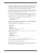
Model 3921Plus Modem Installation CAUTION If the Model 3921Plus is removed from the carrier, always use a ground strap when handling the modem. Always store the Model 3921Plus in an antistatic bag when it is removed from the carrier. The Model 3921Plus is designed for installation in a COMSPHERE 3000 Series Carrier which supplies both the operating power and the leased and/or dial network connections.
Figure 4. Installing a Model 3921Plus Modem If the modem is to communicate with an installed SDCP, install the modem as described above and perform the following steps: 1. Press the Select key on the SDCP. The cursor appears in the slot selection entry. 2. Press the F1 ( ) or F2 ( ) key until the carrier number you want appears on the LCD. The carrier number selection has a range of 1 to 8 since a single SDCP can control a configuration of up to eight carriers.
6. Once you have determined that the modem is installed properly and completed its power-up self-test, rotate the circuit pack lock until it covers the faceplate latch (Figure 5) and tighten the retention screw on the circuit pack lock. This prevents the modem from accidently being removed once it is installed in a carrier. 7. Configure the modem as described in the Selecting Factory Configuration Options section. Figure 5.
Removing and Replacing Model 3921Plus Modems CAUTION If the Model 3921Plus is removed from the carrier, always use a ground strap when handling the modem. Always store the Model 3921Plus in an antistatic bag when it is removed from the carrier. It is not necessary to power down the carrier to remove and replace a Model 3921Plus modem. Perform the following steps: 1. Rotate the circuit pack lock until the release tab is exposed. 2.
18