6238-I2 Wi-Fi Router with VoIP User’s Guide February 2007 Document Part Number: 6238-A2-ZB20-20
Zhone Technologies @Zhone Way 7001 Oakport Street Oakland, CA 94621 USA 510.777.7000 www.zhone.com info@zhone.com COPYRIGHT 2007 Zhone Technologies, Inc. All rights reserved. This publication is protected by copyright law. No part of this publication may be copied, distributed, displayed, modified, transmitted, stored in a retrieval system, or translated without express written permission from Zhone Technologies, Inc.
Table of Contents General Information ............................................................................................... 5 Package Contents .................................................................................................. 5 Safety Instructions—Please Read ......................................................................... 5 Front Panel View .................................................................................................. 6 Indication ....................
Advanced ............................................................................................................ 56 Quality of Service ............................................................................................... 58 Station Info ......................................................................................................... 60 Voice....................................................................................................................... 61 SIP Basic..............
General Information The 6238 Wi-Fi Router with VOIP is a 3-in-1 router having the functions of a standard ADSL router, plus voice capabilities and wireless accessibility, all in one box. These three features add convenience and provide increased functions to one router.
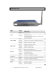
Front Panel View LED Power ADSL / LINK ADSL / ACT LAN 1-4 USB Device Mode Indication Solid The router is on. No light The router is not on. Check if the AC power adapter is connected to the router and plugged in. Solid ADSL is connected. No light ADSL is not connected. ALARM LED will be red. Blinking Router is connected to ADSL. Solid ADSL is connected; no traffic. No light ADSL is not connected. Blinking Presence of ADSL traffic. Solid Router is connected to LAN.
LED Phone2 Phone1 LINE 6238-A2-ZB20-10 Mode Indication Blinking Presence of wireless traffic. Solid Line2 is off-hook. No light Line2 is on-hook. Solid Line1 is off-hook. No light Line1 is on-hook. Solid Line is off-hook. No light Line is on-hook.
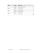
Back Panel View Port Description On / Off Press to turn the router on and off. DC 15V 1.2A Connects to the AC adapter. LINE Connects to the wall outlet using an RJ11 cable. Phone1 Connects to a telephone using an RJ11 cable. Phone2 Connects to a second telephone using another RJ11 cable. Console For use by service personnel only. USB Host Connects to a printer or server using the USB cable provided. USB Device Optional: Use only if not using any of the LAN lines.
Installing the Router Connect the ADSL Line to a POTS Splitter (Optional) Follow this procedure if you connect a telephone to the ADSL line using a POTS splitter. • Connect an RJ11 cable between the wall phone jack and the LINE port of the splitter (see diagram below). • Attach another RJ11 phone wire to the MODEM port of the splitter and the ADSL port on the rear panel of the router. • Attach the PHONE port of the splitter to the telephone using a third RJ11 phone wire.
By USB— Or, you can use the supplied USB cable to connect your computer directly to the router. • Connect one end of the USB cable to the USB port (labeled USB Device) on the back of the router and connect the other end to a free USB port on your PC. Do not use the LAN ports of the router. • The Found New Hardware Wizard will open on your PC. See USB Driver Installation below.
Installation Diagram 6238-A2-ZB20-10 6238 Wi-Fi Router with VOIP User’s Guide 11
Mounting the Router The router can be mounted on the wall with screws. Mounting can be done on wall material including concrete, wood, or drywall. Select an appropriate location free from obstructions or any possible interference. Make sure the cables can be easily attached to the router without strain. The illustration below shows how to mount the router horizontally on a wall.
USB Driver Installation The following instructions will guide you through the installation of the USB driver. The procedure is not required if you use the LAN ports of the router instead of the USB Device port. 1. When you attach the USB cable to the router for the first time and turn on the device, Windows will detect new hardware and the Found New Hardware Wizard will appear.
2. The Found New Hardware Wizard will appear shortly after, showing that a USB driver is needed. Click on Next to continue with the installation. 3. The Digital Signature Not Found window appears. Click on Yes to continue with the installation. 4. The Insert Disk window prompts you to insert the disk (or CD) containing the USB driver. Click on OK after inserting the disk (or CD).
5. After clicking OK at the previous window, you will be asked to browse for the location of the disk (or CD) that the USB driver is on. Then click on OK to continue to the next step. 6. When you select the location of the disk (or CD), the required file USB8023K.SYS is displayed in the filename window of this screen. Click on Open to continue with the installation process.
7. The last window lets you know that the driver installation is complete. Click on Finish to close the wizard. Configuring Your Computer Prior to accessing the router through the LAN or the USB port, your PC’s IP address must be set to 192.168.1.x, where x is any number between 2 and 254. The Subnet Mask must be set to 255.255.255.0. The router’s default IP address is 192.168.1.1. Below are the procedures for configuring your computer. Follow the instructions for the operating system that you are using.
11. Click on OK twice to save your changes and then close the Control Panel. Windows XP 1. In the Windows taskbar, click on the Start button and point to Settings and then click Network Connections. 2. In the Network Connections window, right click on the Local Area Connection icon and click on properties. 3. Listed in the Local Area Connection window are the installed network components. Make sure the box for Internet Protocol (TCP/IP) is checked and then click on Properties. 4.
Log in to the Router This section explains how to log in to your router. 1. Launch your web browser. 2. Enter the URL http://192.168.1.1 in the Address field of your browser and press Enter. A login screen like the one below appears. 3. Enter your user name and password, and then click on OK to display the user interface. NOTE: There are two default user name and password combinations. The user / user name and password combination can display device status, but cannot change or save configurations.
Device Info This section describes the system information that can be accessed using the menu items under Device Info. Summary Access the general information of the router by clicking on Summary under Device Info. The display shows details of the router such as software version, wireless driver version, and LAN IP address. It also displays the current status of your DSL connection.
WAN Access the WAN status report from the router by clicking on “WAN” under “Device Info”. The first time you do this, there is no information to view, since a WAN connection has not been set up yet. After completing the configurations for a WAN connection, you can return to this screen to view the information on your WAN status.
Access the WAN statistics from the router by clicking on the WAN item under Statistics. ATM Statistics Access ATM statistics from the router by clicking on the ATM item under Statistics.
ADSL Statistics You can view ADSL statistics by clicking on the ADSL item under Statistics. Information contained in this screen is useful for troubleshooting and diagnostics of connection problems. ADSL BER Test A Bit Error Rate Test (BER Test) is a test that reflects the ratio of bits in error to the total number transmitted.
Route Access the routing status report from the router by clicking on the Route item under Device Info.
Access the ARP status report from the router by clicking on the ARP item under Device Info. ARP (Address Resolution Protocol) maps the IP address to the physical address, labeled HW Address (the MAC address) and helps to identify computers on the LAN.
DHCP Access the DHCP Leases screen by clicking DHCP under Statistics. This shows the computers, identified by the hostname and MAC address that have acquired IP addresses by the DHCP server with the time that the lease for the IP address is up. Quick Setup This section explains how to quickly configure the router for the single purpose of connecting to the Internet. To use any additional functions of the router, continue to the Advanced Setup section.
If you uncheck the DSL Auto-connect box, the resulting screen is seen below. Enter the VPI / VCI as indicated by your ISP and enable Quality of Service to enable the function. To continue, click on Next.
Next is the Connection Type screen, where you select the type of network protocol and encapsulation mode over the ATM PVC that your ISP has instructed you to use. The following is a PPPoA example. Click on Next to continue. Enter the PPP username and password as given by your ISP. Then decide if you will be using any features such as dial on demand, PPP IP extension, keep alive. Then click on Next.
The next step is to configure the Network Address Translation (NAT) settings. Enable the necessary services and then click on Next to continue. You can configure the DSL Router IP address and Subnet Mask for the LAN interface to correspond to your LAN’s IP Subnet. If you want the DHCP server to automatically assign IP addresses, then enable the DHCP server and enter the range of IP addresses that the DHCP server can assign to your computers.
The next screen allows you to enable or disable the wireless function. If you enable wireless, then enter the wireless network name (SSID). The default SSID (wireless) is already entered. Click on Next to continue. After all of the WAN configurations have been made, the WAN Setup Summary screen displays all WAN settings that you have made. Verify that the settings are correct before clicking on the Save/Reboot button. Clicking on Save/Reboot will save your settings and restart your router.
Advanced Setup This section of the setup is an advanced version of the quick setup. If you want to make specific configurations to your router such as firewall, port mapping, quality of service, or DNS, consider going through this advanced setup for a more comprehensive configuration. WAN Configure the WAN settings as provided by your ISP. The following screen shows the PPPoA connection that was established in the previous Quick Setup example.
Find out the following values from your ISP before you change them. • • • VPI: Virtual Path Identifier. The valid range is 0 to 255. VCI: Virtual Channel Identifier. The valid range is 32 to 65535. Service Category: Five classes of traffic are listed: o o o o o UBR Without PCR (Unspecified Bit Rate without Peak Cell Rate)— UBR service is suitable for applications that can tolerate variable delays and some cell losses.
The next screen shows the below types of network protocols and encapsulation modes: • • • • • PPP over ATM (PPPoA) PPP over Ethernet (PPPoE) MAC Encapsulation Routing (MER) IP over ATM (IpoA) Bridging Select the mode that your ISP has instructed you to use and click on Next. Since this example uses a PPPoA connection, the next screen requires you to enter a PPP username and password. After filling in the page and making any selections your ISP has instructed you to, click on Next to continue.
When the settings are complete, the next screen shows a WAN Setup – Summary screen displaying the WAN configurations made. Click on Save to save the settings. After the settings are saved, the WAN Setup screen displays the WAN settings that you made, with the option to Add or Remove any of the connections that you have made. When satisfied with the settings click on the Finish button.
After selecting the Finish button, the DSL Router Reboot screen appears. The router reboots to save the changes made. Local Area Network (LAN) Setup You can configure the DSL Router IP address and Subnet Mask for the LAN interface to correspond to your LAN’s IP Subnet. If you want the DHCP server to automatically assign IP addresses, then enable the DHCP server and enter the range of IP addresses that the DHCP server can assign to your computers.
Ethernet Mode The Ethernet speed of each of the 4 LAN ports can be configured here. Speed settings include: auto, 100 full, 100 half, 10 full, and 10 half. You can also view the status of each port’s settings, whether it is connected or not and the speed at which it is connected. NAT If you enable NAT (Network Address Translation), you can configure the Virtual Server, Port Triggering, and DMZ Host.
Select the virtual server from the drop-down list and complete the server IP address, then click on the Save/Apply button. Port Triggering Click on the Add button to add Port Triggering to your Internet application. The following screen appears when you click on Add allowing you to select the application that you want to set the port settings for. After a selection has been made, click on the Save/Apply button.
The following screen appears after you save your selections. You will be able to add or remove selections made, by clicking on the Add and Remove buttons.
DMZ Host You can define the IP address of the DMZ Host on this screen. Enter the IP address and click on Save/Apply. Firewall IP Filtering—Outgoing The outgoing filter blocks the LAN traffic from entering the WAN side. Click on the Add button to create filters. The following screen appears when you click on Add. Input the filter name, source information (from the LAN side), and destination information (from the WAN side). Then click on Save/Apply.
The following screen appears when you Save/Apply the IP filter. The screen lists the IP filters that were added from the previous screen. To change your settings, click on the Add or Remove buttons. IP Filtering—Incoming Incoming IP filter filters the WAN traffic to the LAN side. Click on the Add button to add incoming filter settings.
Enter a filter name, information about the source address (from the WAN side), and information about the destination address (to the LAN side). Select the protocol and WAN interface, then click on Save/Apply to add the setting. You can view and delete the incoming filter settings from this screen. MAC Filtering MAC filtering can forward or block traffic by MAC address. You can change the policy or add settings to the MAC filtering table using the MAC Filtering Setup screen.
If you click on Change Policy, a confirmation dialog allows you to verify your change. If you click on the Add button, then the following window allows you to create a MAC filter. If you want to add a setting to the MAC filtering table, enter the Source and Destination MAC address, and select protocol type, frame direction, and WAN interface. Then click on Save/Apply to save it. After you save the settings, a screen showing the settings will appear.
Parental Control In a home setting, parents can also restrict the day of the week certain computers can access the router. Click on Add to set up the restrictions. To set up a restricted user, enter the user name, the MAC address, and select the days to restrict. You can also enter the start and end of the blocking time. When completed, click on Save/Apply.
Quality of Service You can configure the Quality of Service to apply different priorities to traffic on the router. Click on Add to configure network traffic classes. After you click on the Add button, the following screen appears allowing you to set up Quality of Service and Differentiated Services configurations by defining traffic classification rules. NOTE: The following screen is the default screen where Enable Differentiated Service Configuration item has not been enabled.
• Traffic Class Name— The name that you assign this class of traffic for which you are configuring quality of service. • Enable Differentiated Service Configuration— allows you to enable the differentiated service if this checkbox is checked. Note: If this function is enabled, you will only need to assign ATM transmit priority (next item). • Assign ATM Transmit Priority— Select from low, medium, or high priority level for transmitting ATM packets.
• Mark IP Type of Service— Select from the following choices: o o o o o • Normal Service Minimize Cost Maximize Reliability Maximize Throughput Minimize Delay Mark 802.1p if 802.1q is enabled on WAN— (See Connection Type screen located under WAN under the Advanced group.) The values range from 0-7. NOTE: Enter the following conditions either for SET-1 or for SET-2. SET-1 • Physical LAN Port— Select the physical port—Ethernet LAN 1-4, USB, or wireless.
• UDP / TCP Source Port (port or port:port)— If TCP or UDP was selected, then enter the port number. • Destination IP Address— The IP address of the computer where the packets will be sent. • Destination Subnet Mask— The subnet mask for the destination of the packets. • UDP / TCP Destination Port (port or port:port)— If TCP or UDP was selected, then enter the port number. SET-2 • 802.1p Priority— If 802.1q was enabled on WAN, then select a value between 0-7.
The above highlighted items are available to configure only when Enable Differentiated Service Configuration checkbox is checked.
Static Route The Static Route screen can be used to add a routing table (a maximum of 32 entries can be configured). Click on Next to add. Enter the route information and then save and apply your configurations.
RIP If RIP is enabled, the router operation can be configured as active or passive. DNS DNS Server Use the DNS Server screen to enable automatic assignment of a DNS or to specify a primary and secondary DNS. If you uncheck the Enable Automatic Assigned DNS checkbox, two additional entry fields—primary and secondary DNS server—will appear as seen below.
Dynamic DNS Access Dynamic DNS located under DNS. Dynamic DNS (Domain Name Service) is a system that allows more than one IP address to be assigned to one domain name. The following Add dynamic DDNS screen allows you to set up your DDNS server. Select the Dynamic DNS provider from the list—DynDNS.org or TZO. Enter the hostname and the ADSL interface and the username / password provided by the DNS server site. Note that you will need to register first at DynDNS.org.
DSL Advanced Settings The test mode can be selected from the DSL Advanced Settings screen. Test modes include normal, reverb, medley, no retrain, and L3. Tone Settings The frequency band of ADSL is split up into 256 separate tones, each spaced 4.3125 kHz apart. With each tone carrying separate data, the technique operates as if 256 separate modems were running in parallel. The tone range is from 0 to 31 for upstream and from 32 to 255 for downstream.
Port Mapping Port mapping is a feature that allows you to open ports to allow certain Internet applications on the WAN side to pass through the firewall and enter your LAN. To use this feature, mapping groups need to be created. Click on the Add button as displayed below. After clicking on the Add button, the following configuration screen appears, allowing you to enter the groups and the interfaces they are associated with.
Wireless This section allows you to configure wireless settings on your router. Basic The Wireless – Basic screen lets you enable or disable the wireless function. The default setting for wireless is enabled. You can also hide the access point so others cannot see your ID on the network.
Security The next screen is the Wireless – Security screen, which allows you to select the network authentication method and to enable or disable WEP encryption. Note that depending on the network authentication that is selected, the screen will change accordingly so that additional fields can be configured for the specific authentication method. Network authentication methods include the following: • • • • 54 Open— Anyone can access the network. The default is a disabled WEP encryption setting.
• • • • • disabled). TKIP uses 128-bit dynamic session keys (per user, per session, and per packet keys). WPA-PSK (Wi-Fi Protected Access – Pre-Shared Key)—WPA for home and SOHO environments, also using the same strong TKIP encryption, perpacket key construction, and key management that WPA provides in the enterprise environment. The main difference is that the password is entered manually. A group re-key interval time is also required.
Wireless Bridge In this next screen you can select the mode, either access point or wireless bridge that you want the router to be in. In the screen below, Bridge Restrict is enabled, therefore you see the Remote Bridges MAC Address fields. If Bridge Restrict is disabled, then there is nothing left to do afterwards. Click on Save/Apply to continue. Advanced Advanced features of the wireless LAN interface can be configured in this section.
• 54g™ Rate—data rate speed up to 54 MBps which results in faster wireless network access and file transfer. 54g also provides a strong wireless connection as well as quick and safe delivery to its destination. • Multicast Rate— The rate at which a message is sent to a specified group of recipients. • Basic Rate— The set of data transfer rates that all the stations will be capable of using to receive frames from a wireless medium.
in mixed 802.11g/802.11b networks. Turn protection off to maximize 802.11g throughput under most conditions. • WMM (Wi-Fi Multimedia)—feature that improves the experience for audio, video and voice applications over a Wi-Fi network. Quality of Service WMM (Wi-Fi Multimedia)—feature that improves your experience for audio, video and voice applications over a Wi-Fi network. If you enable WMM, then you will need to configure the network traffic classes by clicking on the Add Qos Entry button.
The following screen allows you to set up your wireless traffic quality of service rule. To set up your traffic rule, start by giving a name to the traffic class. Then set up the conditions that must be satisfied for the rule to take effect. Also, assign a wireless transmit priority from the selection of 0-7. The following are the different priority levels to choose from.
Station Info This screen shows computers or other devices accessing your router through its wireless connection.
Voice This section explains the configuration of the voice function of your router. Configurations include basic and advanced SIP setup, phonebook, and call history. SIP Basic Following is the screen for SIP configuration. • • • • • • • • Interface Name— Select the name of the interface that you are using. SIP Mode— Includes peer-to-peer or proxy mode. SIP Proxy— Enter 0.0.0.0 if no proxy server is being used or enter the IP address that was issued by the VoIP service provider when you signed up.
• • • • • • • • • • SIP Outbound Proxy Port— Provided by your service provider. STUN Server— (optional-enter only if you are using this service) – IP address of the STUN server, a protocol for assisting devices behind a NAT firewall or router with their packet routing. STUN Server Port— (optional-used with the STUN server) - UDP port 3478 is the port that the STUN server is contacted on. User 1 ID— this is the phone number (integers only).
• • z z • • • z • • z z z • Preferred Codec— Select the voice encoder that you prefer. This does not guarantee that this encoder will be used, but will be taken into consideration when deciding which voice encoder to use. Each voice encoder varies by the amount of compression on the voice. Packetisation Time (in milliseconds)— This is how often a packet should be sent. This can increase or decrease the time duration between each packet sent.
• • • PSTN Route Rule— For incoming calls using PSTN, this is the line (line 1 or line 2) that the call is received through. You can select auto so that it automatically selects an open line. Route PSTN to VoIP— For incoming PSTN calls you can select whether or not you want to route the call to use VoIP. Route VoIP to PSTN— For incoming VoIP calls you can select whether or not you want to route the call to a PSTN line and which VoIP line you want to be able to route to the PSTN line.
Phone1 and/or Phone2 will generate or receive calls to the PSTN via the Line port on this unit. The user can then select the desired Prefix for switching from PSTN to VoIP network on a per outgoing call basis. Dial Plan The dial plan allows you to create rules for processing the numbers you dial. • Prefix— The prefix numbers that determine the type of call when you dial a string of numbers. This must be at least 1 digit.
• • • • • Min. Accept Digits— The minimum number of digits that must be dialed to be accepted as a correct number. This includes the prefix. Max. Accept Digits— The maximum number of digits that can be dialed to be a valid phone number. This includes the prefix. Delete Digits— The number of digits at the beginning of the dialed number that will be taken off.
SIP Provision This page allows you to set up a provision configuration for downloading SIP settings from a server. All SIP related settings will use the values from the downloading provision file. The following steps will allow you to set up this feature. 1. To enable this feature, click on the Enabled clickbox. 2. Select a Provision Method. The default provision method for downloading the configurations is by TFTP. 3.
Call Features NOTE: Reference Only—This is not a section in the router’s user interface. This is a reference of the feature codes for different call features such as call waiting, call forwarding, etc. Call Feature Function Dial String Call Waiting If call waiting is enabled on a line and you hear the call waiting tone during a call, press flash to answer the second call. The first call is automatically placed on hold. To switch between calls, press flash again.
Speed Dial you are already on the line example, line 1 is ringing, you can off-hook line 2, and dial *99 to answer the incoming call Enables you to speed dial any number that is entered in the Phonebook section of the Voice Page • To speed dial, dial *00 *09 Diagnostics The diagnostics screen allows you to run diagnostic tests to check your DSL connection.
Management The Management section gives you access to certain setups for the purpose of maintaining the system, including backing up the configurations, viewing system log, maintaining access control, and updating software. Settings Backup Settings To save a copy of the configurations that you have made on your router, click on the Backup Settings button. The following pop-up screen appears with a prompt to open or save the file to your computer.
Restore User Settings To load a previously saved configuration file onto your router, click on Browse to find the file on your computer and click on Update Settings. The router restores settings and reboot to activate the restored settings. Restore Default Restore Default deletes all current settings and restore the router to factory default settings. Click on the Restore Default Settings button.
The router restores the default settings and reboot. System Log The System Log dialog allows you to view the System Log and configure the System Log options. To view the System Log, click on the View System Log button. Below is a view of the System Log.
Configure System Log If the log is enabled, the system will log selected events including Emergency, Alert, Critical, Error, Warning, Notice, Informational, and Debugging. All events above or equal to the selected log level will be logged and displayed. If the selected mode is Remote or Both, events will be sent to the specified IP address and UDP port of a remote system log server. If the selected mode is Local or Both, events will be recorded in the local memory.
TR-069 Client The router includes a TR-069 client which is a WAN management protocol. All the values are already filled in. If you wish to enable this protocol, then select enable. You must click on the Save/Reboot button for the change to take place. Internet Time The Time Settings screen allows you to automatically synchronize your time with a timeserver on the Internet. If you choose to automatically synchronize with Internet time servers, then click on the box and the following fields appear.
Access Control You can enable or disable some services of your router by LAN or WAN. If no WAN connection is defined, then only the LAN side can be configured. Services Services that can be enabled include FTP, HTTP, ICMP, SNMP, SSH, TELNET, and TFTP. Click on Apply when finished.
IP Addresses Any access to the router can be controlled when Access Control Mode is enabled. The IP addresses of allowed hosts can be added in the IP Address page under Access Control. On the Access Control – IP Address page, enter the IP addresses of the allowed hosts by clicking the Add button. The IP Address entry page will be displayed as below: Add the IP address of the allowed host into the entry box.
More IP addresses can be added by repeating the above procedures.
Passwords Access the Passwords screen under the Access Control section to change a password. Select an account and enter the current password and the new password. Then click on the Save/Apply button. Update Software If your ISP releases new software for this router, follow these steps to perform an upgrade. 1. Obtain an updated software image file from your ISP. 2. Enter the path to the image file location or click on the Browse button to locate the image file. 3.
Reboot Router Select Reboot Router under Access Control to reboot the router using the web interface. The router saves the current configuration and reboots itself using the new configuration.