IMACS Integrated Multiple Access Communications Server System Reference Guide Publication 999-001966 Release 3.
Running Head Model No. Trademarks: Premisys is a registered trademark of Premisys Communications, Inc. 5ESS is a registered trademark of Lucent Technologies SLC is a registered trademark of Lucent Technologies DMS-100 and DMS-200 are registered trademarks of Nortel FCC Registration number: 1H5SNG-73866-DD-E(integral CSU) B468NR-68618-DM-E(internal modem) Canadian Certification number:1932 5217 A Canadian DOC Load number:5 Ringer Equivalence number: 0.
Important Safety Instructions 1. Read and follow all warning notices and instructions marked on the product or included in this Reference Guide. 2. This product is intended to be used with a three-wire grounding type plug - a plug which has a grounding pin. This is a safety feature. Equipment grounding is vital to ensure safe operation. Do not defeat the purpose of the grounding type plug by modifying the plug or using an adapter.
Model No. Running Head 8. A rare phenomenon can create a voltage potential between the earth grounds of two or more buildings. If products installed in separate buildings are interconnected, the voltage potential may cause a hazardous condition. Consult a qualified electrical consultant to determine whether or not this phenomenon exists and, if necessary, implement corrective action prior to interconnecting the products. 9.
Product Description This integrated access system allows you to take advantage of the sophisticated network services available from long-distance companies, telephone companies, specialized carriers and PTTs. By using these new services, you can increase the capabilities of your private network and simultaneously reduce costs. This Reference Guide will help you put your system to work in your networking environment.
Running Head Model No. System Reference Guide This System Reference Guide assists technicians in unpacking, assembling, configuring, and operating the integrated access device.
Ordering Information To order equipment, cables, or additional copies of this Reference Guide, please contact your distributor. Safety/Regulatory Information Always observe the following precautions. Only qualified technicians should perform these tasks. 1. Never install telephone wiring during a lightning storm. 2. Never install telephone jacks in wet locations unless the jack is specifically designed for wet locations. 3.
Model No. Running Head Individually covered or insulated equipment grounding conductors shall have a continuous outer finish that is either green, or green with one or more yellow stripes. The equipment-grounding conductor must be connected to ground at the service equipment. 2. The receptacles in the vicinity of the product or system must be of a grounding type. The equipment-grounding conductors serving these receptacles are to be connected to earth ground at the service equipment.
Power Source AC: 120 Volts @ 2.0 amps / 240 Volts @ 1 amp, 50/60 Hz DC: +24 Volts @ 3.0 amps / -48 Volts @ 1.5 amps Additionally, the DC source must provide a means of disconnecting power from the supply, and the supply voltage must be provided from an isolated source complying with SELV requirements of EN60950. Fusing To avoid a fire hazard, use only fuses with the specified type and rating with the system.
Running Head Model No. If this equipment causes harm to the telephone network, the telephone company will notify you in advance that temporary discontinuance of service may be required. If advance notice is not practical, the Telephone Company will notify you as soon as possible. Also, you will be advised of your right to file a complaint with the FCC if you believe it is necessary.
Name and Type of Equipment IMACS/600, IMACS/800, IMACS/900 Integrated Multiple Access Communication Server Under 89/336/EEC as amended by 92/31/EEC, and 93/68/EEC In accordance with EN50081-1: EN55022 In accordance with EN50082-1 Under 72/23/EEC as amended by 93/68/EEC EN60950 with Amendments A1 and A2 Under 91/263/EEC In accordance with the following Common Technical Regulations: CTR 12 - as described EC Type Examination Certificate BABT/97/4841 CTR 13 - as described EC Type Examination Certificate BABT/9
Model No. Running Head associated with a single line individual service may be extended by means of a certified connector assembly (telephone extension cord). The customer should be aware that compliance with the above conditions might not prevent degradation of service in some situations. Repairs to certified equipment should be made by an authorized Canadian maintenance facility designated by the supplier.
Europe European Telecommunication Approvals Under the Telecommunications Terminal Directive the following connections are approved: The WAN DUAL card, the WAN SINGLE card, and the 120 ohm version of the DSX/CEPT module are approved for connection to ONP unstructured and structured 2048 kbps digital leased lines with G.703 interfaces, following assessment against CTR12 and CTR13. United Kingdom UK Approval Number The BABT approval number is M606037.
Running Head Model No. The Interface Card is also listed in the approval documentation and provides a direct metallic path between the CEPT module and appropriate Connector Panel. The power required by the host and the total of all adapter cards installed within the host environment, together with any auxiliary apparatus, shall not exceed the power specification of the host apparatus.
PERSÖNLICHE SICHERHEIT BEI INSTALLATION ODER BEI WARTUNG SICHERZUSTELLEN UND UM SCHADEN AN DER EINRICHTUNG ODER AN DER ZUM ANSCHLUß BESTIMMTEN EINRICHTUNG ZU VERMEIDEN. ERDUNG Die Einrichtung kann genauso durch das Netzanschlußkabel wie durch das mit gekennzeichnete Terminal geerdet werden. STROMVERSORGUNG Wechselspannung 120/240 Volts 2/1 Amps 50/60 Hertz Gleichstrom 24/48 Volts 1/1.
Running Head Model No.
Contents Contents Chapter 1 System Overview 1.1 1.2 1.2.1 1.2.2 1.2.3 1.2.4 1.3 Chapter 2 System Installation 2.1 2.1.1 2.1.2 2.1.2.1 2.1.3 2.1.3.1 2.1.4 2.1.4.1 2.1.4.2 2.1.4.3 2.1.5 2.1.5.1 2.1.5.2 2.1.5.3 2.2 2.2.1 2.2.1.1 2.2.1.2 2.2.1.3 2.3 2.3.1 2.3.2 2.3.3 2.3.4 2.4 2.4.1 2.4.1.1 2.5 2.5.1 2.5.2 Reference Guide Introduction ....................................................................................................1-1 Chassis Types .......................................................
Model No. Running Head Contents 2.5.3 2.5.4 2.6 2.7 2.7.1 2.7.2 2.7.3 2.7.4 2.7.5 2.7.6 Chapter 3 System Configuration and Operation 3.1 3.2 3.2.1 3.3 3.3.1 3.3.2 3.3.3 3.3.3.1 3.3.3.2 3.3.4 3.3.5 3.3.6 3.3.7 3.3.8 3.4 3.4.1 3.4.2 3.4.3 3.5 3.5.1 3.5.2 3.5.3 3.5.4 3.6 3.7 3.7.1 3.7.2 3.8 3.8.1 3.8.2 3.9 3.10 3.10.1 3.10.2 ii Front-Loading Chassis with Power Supplies on Top .............................. 2-16 Power Enhanced Chassis with Power Supplies in Front .........................
Contents 3.10.3 3.11 3.12 3.13 3.14 3.15 3.15.1 3.15.2 3.15.3 3.15.4 3.15.5 3.15.6 3.15.7 3.16 3.17 3.18 3.19 3.20 3.21 3.22 3.22.1 3.22.2 3.23 Chapter 4 CPU Card 4.1 4.2 4.2.1 4.2.1.1 4.2.1.2 4.3 4.3.1 4.3.1.1 4.3.1.2 4.3.2 4.4 4.4.1 4.4.1.1 4.4.1.2 4.4.1.3 4.4.1.4 4.4.1.5 4.4.1.6 4.4.1.7 4.4.1.8 4.5 Reference Guide Cross-Connect Model ...............................................................................3-31 Automatic Time Slot Assignment .....................................................
Model No. Running Head Contents 4.6 4.7 4.8 4.9 Chapter 5 Interface Card 5.1 5.2 5.2.1 5.2.1.1 5.2.1.2 5.2.2 5.2.3 5.2.4 5.2.5 5.2.5.1 5.2.5.2 5.2.6 5.2.7 5.2.8 5.2.9 5.3 5.4 5.5 5.5.1 5.5.1.1 5.5.1.2 5.5.2 5.5.3 5.5.3.1 5.5.3.2 5.5.3.3 5.5.3.4 5.5.4 5.6 5.7 5.7.1 5.7.2 5.7.3 Chapter 6 CPU-3 BCON (880020 / 880021 / 880022 / 880060) ................................. 4-33 CPU-3 RCON (880420 / 880421 / 880422 / 880460) ................................. 4-33 CPU Card Error Messages .......................
Contents 6.2.1.2 6.2.2 6.2.2.1 6.2.2.2 6.2.3 6.2.3.1 6.2.3.2 6.2.4 6.2.4.1 6.2.4.2 6.2.5 6.2.5.1 6.2.5.2 6.2.6 6.2.6.1 6.2.6.2 6.2.6.3 6.2.6.4 6.2.6.5 6.2.6.6 6.2.7 6.2.7.1 6.2.7.2 6.2.8 6.2.8.1 6.2.8.2 6.2.9 6.3 6.3.1 6.3.2 6.3.3 6.3.4 6.3.5 6.3.6 6.3.7 6.3.8 6.4 6.4.1 6.4.2 6.4.3 6.4.4 6.4.5 6.4.6 6.4.7 6.4.8 6.5 6.6 Reference Guide Card External Connectors and Signal Pinouts .......................................6-2 WAN DUAL Card Description (801020 / 801021) ...................................
Model No. Running Head Contents Appendix A System Specifications A.1 A.2 A.3 A.4 A.5 A.6 A.7 FCC Requirements ........................................................................................A-1 UK Requirements ..........................................................................................A-2 System Requirements ....................................................................................A-2 Power Requirements ......................................................................
Figures Figures 1-1 1-2 1-3 1-4 1-5 1-6 1-7 2-1 2-2 2-3 2-4 2-5 2-6 2-7 2-8 2-9 2-10 2-11 2-12 3-1 3-2 3-3 3-4 3-5 3-6 3-7 3-8 3-9 3-10 3-11 3-12 3-13 3-14 3-15 3-16 3-17 3-18 3-19 3-20 3-21 Front-Loading Chassis with Power Supplies on the Side....................................................1-2 Front-Loading Chassis with Power Supplies on Top ..........................................................1-3 Two-Sided Chassis Front View ......................................................................
Running Head Figures 3-22 3-23 3-24 3-25 3-26 3-27 3-28 3-29 3-30 3-31 3-32 3-33 3-34 3-35 3-36 3-37 3-38 3-39 3-40 3-41 3-42 3-43 3-44 3-45 3-46 3-47 3-48 3-49 3-50 3-51 3-52 3-53 3-54 3-55 3-56 3-57 3-58 3-59 3-60 3-61 3-62 3-63 3-64 3-65 3-66 3-67 3-68 3-69 viii Model No. Typical WAN Time Slot Assignment Screen ................................................................... 3-35 Typical CPU Cross-Connect Screen .................................................................................
Figures 3-70 3-71 4-1 4-2 4-3 4-4 4-5 4-6 4-7 4-8 4-9 4-10 4-11 4-12 4-13 5-1 5-2 5-3 5-4 5-5 5-6 5-7 5-8 5-9 5-10 5-11 5-12 6-1 6-2 6-3 6-4 6-5 6-6 6-7 6-8 6-9 6-10 6-11 6-12 6-13 6-14 6-15 6-16 6-17 6-18 6-19 6-20 6-21 Typical ADPCM Card Main Screen ..................................................................................3-85 Typical ADPCM Card Redundancy Switch in Progress ...................................................3-86 CPU Card Main Screen..............................................
Running Head Figures 6-22 6-23 6-24 6-25 6-26 6-27 6-28 6-29 6-30 6-31 6-32 6-33 6-34 6-35 6-36 6-37 6-38 6-39 6-40 6-41 6-42 6-43 6-44 6-45 x Model No. DS0 Time Slot Loopback.................................................................................................. 6-20 Using WAN Groups .......................................................................................................... 6-22 WAN Card Main Screen for E1 CEPT or HDSL ...........................................................
Tables Tables 1-1 1-2 1-3 1-4 2-1 3-1 3-2 3-3 3-4 3-5 3-6 3-7 3-8 3-9 3-10 3-11 3-12 4-1 4-2 4-3 4-4 4-5 4-6 4-7 4-8 4-9 4-10 5-1 5-2 5-3 5-4 5-5 5-6 5-7 5-8 5-9 6-1 6-2 6-3 6-4 6-5 6-6 Card Slots for Front-Loading Chassis with Power Supplies on the Side ..........................1-2 Card Slots for Front-Loading Chassis with Power Supplies on Top.................................1-4 Two-Sided Chassis Card Slots ..........................................................................................
Running Head Tables 6-7 6-8 6-9 6-10 6-11 6-12 6-13 6-14 6-15 6-16 xii Model No. CEPT/HDSL Screen Option Settings and Defaults ........................................................ 6-24 Performance Data Screen Actions .................................................................................. 6-30 Far-End Performance Data Screen Actions .................................................................... 6-32 Test Screen Actions .................................................................
System Overview Introduction Chapter 1 System Overview 1.1 Introduction This chapter describes the various chassis models used by the integrated access system. It also shows each chassis and the associated card slot locations. Three series of chassis models are available. These include the front-loading chassis with power supplies on the side; the front-loading chassis with power supplies on top, and the frontand rear-loading chassis with power supplies on the side, also called the two-sided chassis.
Model No. System Overview RunningTypes Head Chassis JP1 S /U R U E 1 2 3 S1 C1 C2 P1 P2 P3 P4 W1 W2 W3 W4 IF R + G V N R S2 R1 - + + - C VA V B O M Figure 1-1. Front-Loading Chassis with Power Supplies on the Side Table 1-1.
System Overview 1.2.2 Chassis Types Front-Loading Chassis with Power Supplies on Top Figure 1-2 shows the front-loading chassis with power supplies on top. This is a tall chassis in which the two power supply slots are in the upper right. This chassis is made of steel and has punched-steel card guides. This chassis has three server card slots (P1 to P3), four WAN card slots (W1 to W4), and eight user card slots (U1 to U8).
Model No. System Overview RunningTypes Head Chassis Table 1-2. Card Slots for Front-Loading Chassis with Power Supplies on Top Type of Card CPU Server WAN Interface Alarm E&M Voice FXS Voice FXO Voice FXS-C Voice FXO-C Voice B7R Data BRI Data DS0-DP Data FRAD Data HSU Data OCU-DP Data SRU Data Main Power (AC/DC) Optional Power Optional Ringer 1.2.
System Overview Chassis Types EUR/US JP1 1 2 3 F1 C1 C2 P1 P2 P3 W1 W2 W3 F2 W4 Figure 1-3. Two-Sided Chassis Front View Figure 1-4 shows the rear of the two-sided chassis, which is the CPE side. The eight user slots (U1 to U8) accommodate a variety of user cards, and the interface slot (IF) is used by the Interface card. Slots R1 to R5 accommodate the optional AC-to-DC power converters and ringing generators.
Model No. System Overview RunningTypes Head Chassis Table 1-3. Two-Sided Chassis Card Slots Type of Card CPU Server WAN Interface Alarm E&M Voice FXS Voice FXO Voice FXS-C Voice FXO-C Voice B7R Data BRI Data DS0-DP Data FRAD Data HSU Data OCU-DP Data SRU Data Main Power (AC/DC) Optional Power Optional Ringer 1.2.
System Overview Chassis Types AC RGR-VNA +VNA -VNB +VNB -VA +VA -VB +VB COMGND- C1 C2 P1 P2 P3 W1 W2 W3 W4 IF U1 U2 U3 U4 U5 U6 U7 U8 C1 C2 P1 P2 P3 W1 W2 W3 W4 IF U1 U2 U3 U4 U5 U6 U7 U8 Figure 1-5. Power Enhanced Chassis The power enhanced chassis works in a specific environment relating to applications using BRI cards. If your environment requires this type of configuration, notify your system administrator for applications design and configuration setup.
Model No. System Overview RunningTypes Head Chassis R1 R2 R3 R4 R5 F1 F2 AC RGR -V NA +V NA -V NB +V NB -VA +V A -VB +V B COM GND - JP1 S /U R U E 1 2 3 C1 C2 P1 P2 P3 W1 W2 W3 W4 IF U1 U2 U3 U4 U5 U6 U7 U8 RGR -V NA +V NA -V NB +V NB -VA +VA -VB +VB COM GND - 1. VNA (+ & -) and VNB (+ & -) are dual -48VDC feeds for the data backplane when -48VDC is to be output from the user card. VNA and VNB are independently protected by 8 amp fuses located on the front panel above the TB connector. 2.
System Overview Chassis Types AC RGR-VNA +VNA -VNB +VNB -VA +VA -VB +VB COMGND- Power Supply and Ringer Supports C1 C2 P1 P2 P3 W1 W2 W3 W4 IF U1 U2 U3 U4 U5 U6 U7 U8 C1 C2 P1 P2 P3 W1 W2 W3 W4 IF U1 U2 U3 U4 U5 U6 U7 U8 Figure 1-7. Power Supply and Ringer Supports for Power Enhanced Chassis Table 1-4.
Running Head U.S. and European Chassis Configuration 1.3 Model No. System Overview U.S. and European Chassis Configuration The chassis can be configured to comply with either U.S. (domestic) or European electrical safety standards by setting a jumper inside each chassis. (Refer to Chapter 2 for details).
System Installation Introduction Chapter 2 System Installation 2.1 Introduction This chapter provides instructions for unpacking and installing the integrated access system chassis and plug-in cards at the user site. It also includes other information you will need to properly install the system, and refers you to other chapters for additional card-level information. The system can operate on either AC or DC power when equipped with the proper power supply.
Running Head Introduction Model No. System Installation 1. Choose a suitable location for the system, as described in this chapter. 2. Unpack and inspect the equipment for damage. 3. Mount the chassis on the desired surface (rack, tabletop, or wall). 4. Set the chassis jumper for U.S. or European operating voltage compliance. 5. Remove the power supply covers from the chassis. 6. Install the chassis ground connections. 7. Install the AC or DC power supplies. 8.
System Installation 2.1.4 Introduction Choosing a Location for Your System The integrated access system requires a reasonably dust-free, static-free operating environment, such as a computer room. Adequate ventilation is also required at the site. Do not install the chassis in direct sunlight, which may increase the system’s operating temperature and affect its operation. Most of the system plug-in cards have highly sensitive components that could be damaged by static electricity.
Model No. System Installation Running Head Introduction 2.1.4.2 Wall-Mount Installation Tips To mount the chassis on a wall, first obtain a piece of standard, marine-grade plywood (3/8 inch diameter, typical) and bolt it firmly to the desired mounting surface. This board must be long and wide enough to cover the entire chassis length and height. The surface must be able to support the total weight of the system (chassis plus plug-in cards). 2.1.4.
System Installation Introduction The brackets are also reversible for mounting in 19-inch or 23-inch racks (48.2 or 58.4 cm). For a 19-inch rack, attach the long sides of the brackets to the chassis. For a 23-inch rack, attach the short sides of the brackets to the chassis. Key: Oval Holes for Rack Attachment Round Holes for Rack Attachment Holes for Tabletop Attachment Holes for Plastic Inserts ("Feet") Figure 2-2.
Model No. System Installation Running Head Introduction Top F r o n t B a c k t t Bottom Figure 2-3. Mounting Holes for Front-Loading Chassis with Power Supplies on Top 2.1.5.3 Two-Sided Chassis The two-sided chassis have 12 holes on each side, as shown in Figure 2-4. These holes facilitate mounting in a 19- or 23-inch rack (48.2 or 58.4 cm).
System Installation Power Supplies and Ringing Generators Be sure both the front and rear of the chassis are accessible for inserting and removing cards. The voice, data, and WAN cards, and the power cables, are attached to connectors at the rear of the chassis. Table 2-1 lists the minimum clearances required between the system chassis and the nearest objects. Table 2-1. Minimum Two-Sided Chassis Clearances Clearance Inches Centimeters 2.
Model No. System Installation Running Head and Ringing Generators Power Supplies 2.2.1.2 Ringing Generators Ringing generators are needed if the system has FXS or FXS-C cards, or if it has FXO or FXO-C cards with ports connected to Manual Ringdown (MRD) circuits. The 20 Hz ringing voltage may be provided either by an external source or with a Ringing Generator, which requires the presence of -48 VDC in the system. Two Ringing Generator models are available (105 VAC output and 100 VAC output).
System Installation Installing the System Power Cards Also be sure to set the same jumper on the system resource cards and external alarm cards to agree with the above setting for the chassis. Refer to the associated chapters in this guide for more information on those card jumpers. 2.3 Installing the System Power Cards Next, install power supplies, AC-to-DC power converters, and ringing generators into the system chassis, as described in this section.
Running Head Installing the System Power Cards Model No. System Installation If the power supply is installed and power is applied, the green LED on the front panel of the power supply should light. A problem exists if this LED does not light. Verify that the power supply is properly seated in the connector. If so, also check the external power source and connection to the power supply. If the power supply, external power source, and power connection are okay, replace the converter.
System Installation Ringing Generators Fus e Power Bus Edge C o nn e c to r H a n d le Figure 2-6. -48V Converter Fuse 2.4 Ringing Generators The ringing generator provides a ringing voltage of either 100 or 105 VAC (nominal) at 20 Hz for simultaneously ringing 11 voice ports. If more than one ringing generator is required in the same chassis, they must have the same model number. The 100V and 105V Ringing Generators cannot be mixed in a single chassis.
Model No. System Installation RunningGenerators Head Ringing 3. For a two-sided chassis, remove the panel covering the rear power slots. You can insert the generator into any of the five rear slots. For the front-loading chassis with power supplies on top, remove the panel covering the front power slots, and insert the module in any of the five slots. For the front-loading chassis with power supplies on the side, insert the ringing generator only into slot R1. 4.
System Installation System Power and Ground Connections 3. Also make sure jumper JP2 is installed on the card, Figure 2-8. This jumper ensures electrical compliance with all chassis. Never remove it for any reason! 4. For a two-sided chassis, remove the panel covering the rear power slots. You may insert or remove the module in any of the five rear slots.
Running Headand Ground Connections System Power 2.5.1 Model No. System Installation Two-Sided Chassis Figure 2-9 shows the power connector block on the front-loading chassis with power supplies on the side, and on the two-sided chassis. Connect the grounds and DC power signals to this block by inserting the wires in the proper slots, then tightening the screws adjacent to the slots to secure the connections. For safety reasons, no more than one-eighth inch (0.
System Installation System Power and Ground Connections POWER CONNECTIONS R G VN R + - C VA VB O - + + - M 48 VDC PSU AC* third wire* ground - -48VDC Return + -48 VDC Supply AC PLUG Optional Telecom Ground (Note: on Optional Telecom Ground Connection: It may be required when the 48VDC PSU output is not grounded or when the system is AC powered. It is only needed for the proper operation of the Telecom Ground Start and E&M signaling circuits.
Model No. System Installation Running Headand Ground Connections System Power POWER CONNECTIONS R G VN R + - C VA VB O - + + - M 48 VDC PSU AC* third wire* ground - -48VDC Return + -48 VDC Supply AC PLUG Optional Telecom Ground (Note: on Optional Telecom Ground Connection: It may be required when the 48VDC PSU output is not grounded or when the system is AC powered. It is only needed for the proper operation of the Telecom Ground Start and E&M signaling circuits.
System Installation System Power and Ground Connections POWER CONNECTIONS 48 VDC PSU RGR AC* third wire* ground - -48 VDC Supply + -48VDC Return AC PLUG +V N VA + +V B COM Optional Telecom Ground (Note: on Optional Telecom Ground Connection: It may be required when the 48VDC PSU output is not grounded or when the system is AC powered. It is only needed for the proper operation of the Telecom Ground Start and E&M signaling circuits.
Model No. System Installation Running Head Powering Up the System D/ C Power Connect ions 48 VDC PSU AC" t hi r dwi r e" gr ound + - 4 8 VDCS uppl y - 4 8 VDCRet ur n AC PLUG RGR - VNA + VNA - VNB + VNB - VA + VA - VB + VB COM Note: This diagram only depicts one DC power source which would support the F1 power supply. If a redundant power configuration is desired, then a second power source would be applied to the VB (+ & -) leads.
System Installation Installing the Other Plug-In Cards If AC-to-DC converters are used, also check their jumper settings as previously described. If all of these conditions are met, replace the card on which the green LED fails to light; that card is faulty. 2.7 Installing the Other Plug-In Cards Also install the remaining cards into their designated chassis slots. Some cards have on-board switches or jumpers that you must set before insertion into the chassis.
Running Head Installing the Other Plug-In Cards 2.7.5 Model No. System Installation User Cards The system also has numerous user cards for connections to voice and data circuits at the CPE, and alarm cards for system alarm reporting to/from external facilities. The user cards go in slots U1 to U8 of the two-sided chassis and front-loading chassis with power supplies on top. Or, they go in slots P1 to P4 and W1 to W4 of the front-loading chassis with power supplies on the side.
System Configuration and Operation Basic Operations Chapter 3 System Configuration and Operation 3.1 Basic Operations This chapter provides instructions for configuring the integrated access server for operation after installing it at the equipment site. Before performing the procedures in this chapter: 1. Be sure your integrated access system is installed and powered up. 2. Determine your system’s specific configuration requirements.
Model No. System Configuration and Operation Running Head Basic Screen Map and Legend 6. Select the type of chassis used (front-loading with power supplies on the side, front-loading with power supplies on top, or front/rear loading with power supplies on the side). 7. If the vendor code and chassis types selection are both correct, type Y to confirm and save that data. Otherwise, type N to return to the screen for changes. The system now automatically restarts with the correct application parameters.
System Configuration and Operation 3.3.1 Basic Screen Map and Legend Starting a Session The first step in starting an operator session is to log into the system. You must enter a password that allows you to perform the required tasks on the system. The initial (default) login passwords correspond to four different access levels, each allowing you to perform certain tasks. Table 3-1 lists the default passwords and describes the access levels.
Model No. System Configuration and Operation Running Head Basic Screen Map and Legend Node_1 | | 12-31 Your Company Name Your Product Name Password: Node: Version: Node_1 3.7 Figure 3-2. Typical Login Screen 3. Contact your system administrator for your Password. Then, press RETURN to accept the password, which will allow you to configure your system after logging in for the very first time. Refer to the next section for descriptions of the various operator password levels. 4.
System Configuration and Operation Node_1 Slot C1 C2 P1 P2 P3 W1 W2 W3 W4 F1 F2 Basic Screen Map and Legend | Installed CPU XCON ADPCM-64 ADPCM-64 CSU+CSU CSU+CSU CEPT+CEPT CEPT+CEPT PS1 PS2 | 12-31-99 Status Slot IF U1 U2 U3 U4 U5 U6 U7 U8 RI Installed INTF+modem ALR E&M 4Wx8-6 FXS 2Wx8-9 FXO 2Wx8-9 HSU 366x2 OCU-DPx5 FRAD-18 SRU-232x10 RINGER 14:33 Status Alarms | Config | Del | accepT | Xcon | sYs | Logout | Oos | cpusWtch Figure 3-3.
Running Head Basic Screen Map and Legend Node_1 Model No. System Configuration and Operation | | 12-31-99 Slot Installed C1 C2 P1/U1 P2/U2 P3/U3 P4/U4 W1/U5 W2/U6 W3/U7 W4/U8 IF S1 S2 S3 CPU RCON CPU RCON ADPCM-64 ADPCM-64 E&M 2Wx8-6 FXS 2Wx8-9 FXO 2Wx8-9 CSU+CSU CSU+CSU CEPT+CEPT INTF+modem PS1 PS2 Ringer 14:33 Status RDNT Alarms | Config | Del | accepT | Xcon | sYs | Logout | Oos | cpusWtch Figure 3-4. Typical System Main Screen (Front-Loading Chassis with Power Supplies on the Side) 3.3.
System Configuration and Operation Basic Screen Map and Legend Table 3-2. System Main Screen Actions Action Alarms Config Del accepT Xcon sYs Logout Oos cpusWtch 3.3.3.2 Function Brings up the Alarm Screen. Refer to "Alarms and Alarm Filters” later in this chapter. Sets up the system using a standard configuration. Removes an out-of-service (OOS) card from system memory. Removes the current card settings. Used when replacing a card in any slot with a different kind of card.
Model No.
System Configuration and Operation 3.3.5 Basic Screen Map and Legend Card Main Screens Each card in the system has a Card Main Screen associated with it. You can go from the System Main Screen to any Card Main Screen and configure that card. From a Card Main Screen, you can go to a Test Screen to perform tests on the card, a Status Screen to see its current operating status, or (in some cases) a Performance Monitor Screen to view transmission performance data. Figure 3-6 shows a typical Card Main Screen.
Model No. System Configuration and Operation Running Head Basic Screen Map and Legend Node_1 | IF PRIMARY CLK EXT RATE EXT FORMAT EXT FRAME 1 int n/a n/a n/a SECONDARY CLK EXT RATE EXT FORMAT EXT FRAME int n/a n/a n/a CURRENT CLK int int ext serv INF+M wan Rev A2-0 Ser 01103 | 12-31-99 14:33 OOS U3 user Save | Undo | Refresh | Time | ACO | proFiles | taBs | Ports | Main Figure 3-6.
System Configuration and Operation 3.3.7 Card Configuration Test and Debug Screen You can also go from the System Main Screen to a Test and Debug Screen, which allows you to perform system-level maintenance operations. You can back up the system configuration onto an external computer after saving and subsequently editing it, and (if necessary) you can restore that configuration to the system. You also can erase the system configuration and restart the system with a single “zip” command.
Running Head Card Configuration Model No. System Configuration and Operation Be sure to configure each card according to your networking requirements. From the System Main Screen, select each card in turn and change the options for that card from its Main Screen. Select the Save command by pressing “s” after making all the changes for a card, then press “m” to return to the System Main Screen and choose another card. Similarly configure each remaining card in your system.
System Configuration and Operation 3.5 Alarms and Alarm Filters Alarms and Alarm Filters Alarms warn you of problems by reporting possible system hardware or external facility failures. The Alarm sub-screens are accessed from the System Main Screen by pressing the "A" key to go to the Alarm Screen (see Figure 3-7 through Figure 3-9). The Alarm Screen displays the currently active alarms (if any) and provides access to the Alarm Filters and Alarm History screens.
Running Head Alarms and Alarm Filters Model No. System Configuration and Operation The third entry (CSU + CSU) shows the type of card affected (in this case, a WAN card with two T1 CSU modules). The fourth entry shows the alarm modifier (in this case, C indicates a critical alarm). See the “Alarms and Alarm Filters” section later in this chapter for more information about alarm modifiers. The fifth entry (CGA_RED) shows the type of alarm generated (in this case, a CGA-Red alarm on WAN port W1-1).
System Configuration and Operation Node_1 OOS NOS LOS YEL AIS CGA_RED CGA_YEL EER SENSOR DCHAN SWITCH UCA RESET ACO SYNC EER-3 PLC_OOF PLC_LOF PLC_YEL Alarms and Alarm Filters | | 12-31-99 Out of Service No Signal Loss of Sync Yellow Alarm Alarm Info Signal Carrier Group–Red Carrier Group–Yellow Excessive Error Rate Alarm card sensor D-chan out of service Switch to redundant card User card/port alarm System reset Alarm Cut-Off Clock Sync Alarm Error rate above 10e-3 DS3 PCLP Out of Framing DS3 PCLP Los
Running Head Alarms and Alarm Filters Model No. System Configuration and Operation The last column sets the alarm cutoff (ACO) to aco-off or aco-on. These settings are explained later in this chapter. The filter in the third column takes precedence over its modifier. If, for instance, you have an alarm filter set to ignore, the setting of the modifier as info, minor, major, or crit will be ignored. Refer to system specifications section in this manual for alarms and their meanings.
System Configuration and Operation 3.5.2 Alarms and Alarm Filters Alarm Modifiers Each alarm may also be designated as info, minor, major or crit. The filter modifier shows on both the active alarm and alarm history screens. If the system has an External Alarm card (optional), the occurrence of any alarm designated as crit will trigger a form-C relay contact on the External Alarm card. The relay contact action sets off an annunciator or lamp at the equipment site.
Model No. System Configuration and Operation Running Headthe System Reinitializing All alarms (except those set to ignore) appear in the Alarms field in the upper right corner of the screen, regardless of their setting in the Alarm Filters screen. The display in the Alarms field is an abbreviated version of the alarm name and slot number. For example, OOS U3 indicates that the card in user slot U3 is out of service.
System Configuration and Operation Reinitializing the System When you remove and replace most card types, the NVRAM remembers the old card’s settings. If the same kind of new card is inserted in the slot, you do not need to reprogram the settings. However, if you replace a card with a different type of card, the system lets you delete the old card, so that you can program new parameter settings for the new card (see the Accept function described earlier in this chapter).
Model No. System Configuration and Operation Runningthe Head Zipping System If the new CPU card was inserted accidentally, the cold-start can be stopped by removing the wrong CPU card and replacing it with the correct type of card. WARNING! The "Z" command will start the ZIP process. "Zipping" the system deletes all of the information stored on NV-RAM and resets it. All cards must then be completely reconfigured.
System Configuration and Operation Zipping the System Test and Debug Zip will reboot the system. Ok to Zip (y/n)? Zip | Debug | Reg | Backup | rEstore | Main Figure 3-11. Zip Screen 3.7.1 Debugging the System The D (Debug) command is only available to factory software engineers with a password authorization higher than "Superuser." It gives access to the system software coding. 3.7.
Running Head Test, Debug, Backup, & Restore 3.8 Model No. System Configuration and Operation Test, Debug, Backup, & Restore Advanced configuration and diagnostics are available through the use of the sYs (sYstem) command from the System Main Screen. Pressing “y” brings up the Test and Debug screen shown in Figure 3-12. Test and Debug Zip | Debug | Reg | Backup | rEstore | Main Figure 3-12. System Test and Debug Screen 3.8.
System Configuration and Operation Test, Debug, Backup, & Restore Because the Backup command creates a simple text file, the actual commands for the Backup procedure will vary depending on the computer system and terminal software you are using to interface with the system. The backup procedure below is specific to Windows 95 using Microsoft Hyper 4 Terminal software, but it can easily be modified to adapt to other systems and software.
Running Head Test, Debug, Backup, & Restore Node_1 C1 C2 P1 P2 P3 P4 W1 W2 W3 W4 IF U1 U2 U3 U4 U5 U6 U7 U8 | Model No. System Configuration and Operation NVRAM Backup backup backup backup backup backup backup backup backup backup backup backup backup backup backup backup backup backup backup backup Install Table Cross Connect Alarm Filters Alarms History | 12-31-99 14:33 backup backup backup backup Go | Copy | Main Figure 3-13.
System Configuration and Operation Test, Debug, Backup, & Restore 1. From the Main Screen, type Y (for sYs). 2. Type E (for rEstore). In the screen shown in Figure 3-14, the default for all slots and categories is restore. To do a full restore, proceed to Step 3. If you do not want to restore a certain slot, use the arrow keys to highlight it, and press . The choices no and backup appear at the bottom of the screen. Use the left arrow key to highlight no, and press .
Model No. System Configuration and Operation Running Time Slot Head Assignment Node_1 C1 C2 P1 P2 P3 P4 W1 W2 W3 W4 IF U1 U2 U3 U4 U5 U6 U7 U8 | restore restore restore restore restore restore restore restore restore restore restore restore restore restore restore restore restore restore restore NVRAM Restore Install Table Cross Connect Alarm Filters Alarms History | 12-31-99 14:33 restore restore restore restore Go | Copy | Main Figure 3-14. Restore Screen 3.
System Configuration and Operation Assigning Time Slots to a User Card The following sections of this chapter describe several ways for you to administer your networks and correctly allocate transmission bandwidth to meet your needs. The next section deals with assigning time slots to the user voice and data card. The second section describes a time-saving tool known as the Configuration option, which automatically assigns sequential WAN time slots to the ports of user voice cards.
Model No. Running Head Assigning Time Slots to a User Card System Configuration and Operation WAN 1-1 TS# 1-8 1 2 3 4 5 6 7 8 1 E&M 2 HSU Card Card TS# 9-16 TS# 17-24 WAN 1-2 TS# 17-24 Figure 3-15. Time Slot Assignment Example Each port of the E&M card can only be assigned a single WAN time slot, or 64 kbps of bandwidth on a T1 or E1 link. The same is true for the ports on all other types of voice cards.
System Configuration and Operation Assigning Time Slots to a User Card 4. Set the time slot number by using the up and down arrow keys to highlight it, then press the key. 5. Change the STATE of the port from stdby to actv. 6. Repeat steps 2 through 5 for the remaining card ports, to assign time slots to them. 7. Press “s” to save your settings, using the Save command in the Card Main Screen.
Model No. Running Head Assigning Time Slots to a User Card System Configuration and Operation 2. Select the WAN port to which you want to assign the HSU port. In Figure 3-17, this port is W1-1 (for WAN 1, port 1). Select the TS table. All time slots of the selected WAN port appear at the bottom of the screen. These are 1 to 24 for a T1 port, or 1 to 31 for an E1 port Place an “X” under each desired time slot, using the space bar to either select or de-select a time slot.
System Configuration and Operation Automatic Time Slot Assignment 3.10.3 Cross-Connect Model The Cross-connect model allows you to access two T1/E1 links for each of four WAN cards, for a total of eight T1/E1 links. All WAN card connections to other WAN cards are accomplished through the cross-connect option on the System Main Screen, and must be individually specified. User cards on systems equipped with a CPU XCON card are assigned to WAN time slots. 3.
Running Head Automatic Time Slot Assignment Model No. System Configuration and Operation 1. Reserve three vacant adjacent user card slots in the system chassis for T1 operation, or four vacant adjacent user card slots for E1 operation. These slots must have voice cards. 2. Set the MODE of the desired WAN port to term. 3. Make sure all voice cards you intend to configure are of the same type. 4. Place the cursor on the first user card slot that will have a card.
System Configuration and Operation Node_1 | Slot C1 C2 P1 P2 P3 W1 W2 W3 W4 F1 F2 e&m-6 Automatic Time Slot Assignment | 12-31-99 Installed CPU XCON Status ADPCM-64 ADPCM-64 ADPCM-64 CEPT+CEPT CEPT+CEPT CSU+CSU CSU+CSU PS1 PS2 e&mer fxs-9 fxs-6 Slot IF U1 U2 U3 U4 U5 U6 U7 U8 R1 fxo-9 Installed INTF+modem ALR E&M 4Wx8-6 FXS -2Wx8-9 FXS -2Wx8-9 14:33 Status RINGER fxo-6 Alarms | Config | Del | accepT | Xcon | sYs| Logout | cpuSwtch Figure 3-19.
Running Head Automatic Time Slot Assignment Node_1 Slot C1 C2 P1 P2 P3 W1 W2 W3 W4 F1 F2 Model No.
System Configuration and Operation Node_1 TS 0 1 2 3 4 5 6 7 8 9 10 11 12 13 14 15 | W1 XCON TS frame align U5-1 A-01 U5-2 A-02 U5-3 A-03 U5-4 A-04 U5-5 A-05 U5-6 A-06 U5-7 A-07 U5-8 A-08 U6-1 A-09 U6-2 A-10 U6-3 A-11 U6-4 A-12 U6-5 A-13 U6-6 A-14 U6-7 A-15 CEPT+CEPT CIRCUIT_ID 64k user_circuit user_circuit user_circuit user_circuit user_circuit user_circuit user_circuit user_circuit user_circuit user_circuit user_circuit user_circuit user_circuit user_circuit user_circuit Cross-Connecting WAN Time Sl
Running Head Cross-Connecting WAN Time Slots Model No. System Configuration and Operation Table 3-4. T1-to-E1 Cross-Connections in Drop-and-Insert Mode T1 DS0 1 2 3 4 5 6 7 8 9 10 11 12 E1 DS0 1 2 3 5 6 7 9 10 11 13 14 15 T1 DS0 13 14 15 16 17 18 19 20 21 22 23 24 E1 DS0 17 18 19 21 22 23 25 26 27 29 30 31 You can cross-connect WAN time slots from the System Main Screen. To perform cross-connections, press “x” in that screen to invoke the Xcon command (with CPU XCON).
System Configuration and Operation Cross-Connecting WAN Time Slots Table 3-5.
Running Head Cross-Connecting WAN Time Slots Model No. System Configuration and Operation WARNING! When cross-connecting multiple independent data DS0 time slots (sequential grouped time slots should work) for data. (Supergroup is multiple DS0’s sequentially assigned) between WAN aggregates in a cross-connect system. DO NOT attempt to save time by cross-connecting independent data time slots as one super-rate circuit (could cause data errors.) This limitation does not apply to voice time slots.
System Configuration and Operation Node_1 | C1 page: 1 of CPU-3 XCON Cross-Connecting WAN Time Slots Rev A0-0 Ser 00101 | 12-31-99 14:33 1 CIRCUIT ID W/U TS/BW TEST W/U TS/BW TEST TYPE TC CNV SF01-NY01 w1-1 00*64 off w1-1 00*64 off d n/a n/a w1-1 w2-1 w2-2 w3-1 w3-2 w4-1 w4-2 w1-2 Save Figure 3-25. WAN Unit Options TS/BW The first Time Slot/Bandwidth column shows the different time slots of w1-1 that will be assigned to this pass-through connection.
Running Head Cross-Connecting WAN Time Slots Node_1 page: | C1 1 CIRCUIT ID of CPU-3 XCON Model No. System Configuration and Operation Rev A0-0 Ser 00101 14:33 1 W/U TS/BW TEST W/U TS/BW 00x64 off w1-1 00x64 1 1 1 1 1 1 1 1 1 1 2 2 2 2 2 1 2 3 4 5 6 7 8 9 0 1 2 3 4 5 6 7 8 9 0 1 2 3 4 x x x x x SF01-NY01 | 12-31-99 w1-1 TEST TYPE TC CNV off d n/a n/a Save Figure 3-26.
System Configuration and Operation Node_1 | C1 page: 1 of CPU-3 XCON Cross-Connecting WAN Time Slots Rev A0-0 Ser 00101 | 12-31-99 14:33 1 CIRCUIT ID W/U TS/BW TEST W/U TS/BW TEST TYPE TC CNV SF01-NY01 w1-1 05x64 off w1-1 00x64 off d n/a n/a off all 0 all 1 m_oos 1:1 1:7 lpbk 300Hz 1KHz 3KHz Save Figure 3-27. Test Options W/U The second WAN Unit column is the T1/E1 link in which the pass-through connection ends. The options are all of the WAN cards and ports.
Running Head Cross-Connecting WAN Time Slots Model No. System Configuration and Operation TEST The second Test column lets you select the test pattern to be applied to this circuit toward the second WAN link specified. Figure 3-27 shows the option set to off.
System Configuration and Operation Node_1 | C1 page: 1 of CPU-3 XCON Cross-Connecting WAN Time Slots Rev A0-0 Ser 00101 | 12-31-99 14:33 1 CIRCUIT ID W/U TS/BW TEST W/U TS/BW TEST TYPE TC CNV SF01-NY01 w1-1 05*64 off w3-2 05*64 off d moos n/a v v&s d Save Figure 3-28. Cross-Connect Circuit Type Selection TC You can define the pattern to be transmitted on a cross-connected circuit if one of the circuit’s two WAN links fails.
Running Head Cross-Connecting WAN Time Slots Model No. System Configuration and Operation For v (voice), no TC choice is available, so the system always shows n/a (not applicable). This is shown as Figure 3-31.
System Configuration and Operation Node_1 page: | C1 1 of CPU-3 XCON Cross-Connecting WAN Time Slots Rev A0-0 Ser 00101 | 12-31-99 14:33 1 CIRCUIT ID W/U TS/BW TEST W/U SF01-NY01 w1-1 user 05*64 0x00 off w3-2 Enter 2 hex digits: TS/BW TEST 05*64 off user 0x00 TYPE TC CNV v&s e&m no 0x00 Save Figure 3-30.
Running Head Cross-Connecting WAN Time Slots Model No. System Configuration and Operation CNV The Conversion (CNV) parameter allows you to request that PCM companding and signaling conversion be performed on this cross-connect circuit. Since these conversions only apply to voice circuits, if the TYPE selected is d (data), then the only acceptable value here is n/a. Similarly, if the TYPE selected is v (voice without signaling), the system will only allow users to request PCM companding conversion.
System Configuration and Operation Node_1 page: | C1 1 of CPU-3 XCON Cross-Connecting WAN Time Slots Rev A0-0 Ser 00101 | 12-31-99 14:33 1 CIRCUIT ID W/U TS/BW TEST W/U TS/BW TEST TYPE TC CNV SF01-NY01 w1-1 05*64 off w3-2 05*64 off v&s e&m pcm A-mu mu-A Select PCM CONV: none Save Figure 3-32.
Running Head Cross-Connecting WAN Time Slots Node_1 | C1 page: 1 of Model No. System Configuration and Operation CPU-3 XCON Rev A0-0 Ser 00101 | 12-31-99 14:33 1 CIRCUIT ID W/U TS/BW TEST W/U TS/BW TEST TYPE TC CNV SF01-NY01 w1-1 05*64 off w3-2 05*64 off v&s e&m pcm Select SIG CONV: none ANSI-CCITT CCITT-ANSI ABCD-ABAB ABCD-AB01 Save Figure 3-33.
System Configuration and Operation Cross-Connect Actions 3.13 Cross-Connect Actions Table 3-6 summarizes the actions you can perform from the CPU Cross-Connect Screen. These actions appear at the bottom highlighted line of the screen. Table 3-6. CPU Cross-Connect Screen Actions Action Add uPdate dElete pgUp pgDn View all Save Function Allows you to program additional pass-through cross-connects in the system.
Model No. System Configuration and Operation Running Head Actions Cross-Connect Node_1 page: | C1 1 of CIRCUIT ID SF01-NY01 CPU-3 XCON Rev A0-0 TS/BW 05*64 W/U w3-2 Ser 00101 | 12-31-99 14:33 1 W/U w1-1 TEST off TS/BW 05*64 TEST off TYPE v TC n/a CNV no Delete Selected Circuit (y/n)? Add | uPdate | dElete | pgUp | pgDn | View all | Tads | Main Figure 3-35.
System Configuration and Operation Testing Voice Cross-Connects Figure 3-36 shows the WAN card in TS (time slot) 8 through 12 being updated. However if the WANs are selected and deleted as shown in Figure 3-35 then the screen in Figure 3-36 will be blank for WAN TS 8 through 12. 3.14 Testing Voice Cross-Connects Voice and data circuits differ in the way the test function is accessed.
Model No.
System Configuration and Operation Testing Voice Cross-Connects Table 3-7.
Running HeadCross-Connects Testing Voice Model No. System Configuration and Operation PATTERN The Pattern parameter allows you to choose a test pattern to be transmitted as PCM data on the selected side of the circuit. The options are off, all 0 (zero), all 1 (one), m_oos (multiplexer out of synchronization), 1:1 (a 1 followed by a zero and then another 1), 1:7 (a zero followed by a 1 and seven zeros, then another 1), lpbk (loopback), 300 Hz (300 Hz tone), 1KHz (1 kHz tone) and 3KHz (3 kHz tone).
System Configuration and Operation Using the Broadcast Option 3.15 Using the Broadcast Option One of the special features of WAN time slot assignment in cross-connect systems is the ability to copy a data signal and send it to multiple locations without disturbing the original circuit. This feature is called broadcasting, which means “multi-cast” (not to be confused with broadcast-quality video transmission).
Model No. System Configuration and Operation Running Using the Head Broadcast Option Broadcast circuits can be initiated, updated, or deleted only from the broadcast screen. To access the Broadcast option, press "v" (for View all) in the Main Cross-Connect Screen. The All Circuits Screen of Figure 3-42 appears. In addition to the WAN card-to-WAN card cross-connects, this screen also shows all user card-to-WAN card time slot assignments for all WAN cards.
System Configuration and Operation Node_1 page: | C1 1 of CPU-3 XCON Using the Broadcast Option Rev A0-0 Ser 00101 | 12-31-99 14:33 1 CIRCUIT ID user_circuit user_circuit SF-SLC HST-PHX W/U w4-1 w4-2 w1-1 w1-2 TS/BW 06*56 06*56 01*64 01*64 TEST off off off off W/U w1-1 w2-2 w2-1 w2-2 TS/BW 06*56 06*56 01*64 01*64 TEST off off off off TYPE d d v v TC n/a n/a n/a n/a CNV n/a n/a no no user_circuit w4-1 06*56 off w1-1 00*56 off b/d n/a no Lecture Save Figure 3-43.
Model No.
System Configuration and Operation Node_1 | C1 page: 1 of CIRCUIT ID user_circuit user_circuit SF-SLC HST-PHX Lecture CPU-3 XCON Using the Broadcast Option Rev A0-0 Ser 00101 | 12-31-99 14:33 TYPE d d v v b/d CNV n/a n/a no no no 1 W/U w4-1 w4-2 w1-1 w1-2 w4-1 TS/BW 06*56 06*56 01*64 01*64 06*56 TEST off off off off off W/U w1-1 w2-2 w2-1 w2-2 w2-1 TS/BW 06*56 06*56 01*64 01*64 06*56 TEST off off off off off TC n/a n/a n/a n/a n/a Bcast | uPdate | dElete | pgUp | pgDn | Main Figure 3-
Model No.
System Configuration and Operation Using the Broadcast Option Table 3-8. Broadcast Screen Actions Action Bcast uPdate dElete pgUp pgDn Main Function Bcast allows users to program additional broadcast cross-connects in the system. If mistakes are made during the add process, pressing the up arrow or down arrow key will terminate this operation. The uPdate action is initiated by pressing the "p" key. With this command, users can change any of the parameters of a broadcast connection.
Model No. System Configuration and Operation Running Using the Head Broadcast Option Node_1 page: | C1 10161 CPU XCON COM 407535038 Ser 00101 1 CIRCUIT ID Jacksonville of | 12-31-99 14:33 1 FACILITY w1-1 01*64 TEST off EQUIPMENT w1-2 01*64 TEST off TYPE d TC moos CNV n/a moNitor | spLit | Release | Tla | pgUp | pgDn | Main Figure 3-49. The TADS screen In Figure 3-49, the data circuit called “Jacksonville” is connected on a single time slot between WAN1-1 and WAN1-2. 3.15.
System Configuration and Operation Node_1 page: Using the Broadcast Option | C1 10161 CPU XCON COM 407535038 Ser 00101 1 of | 12-31-99 14:33 1 CIRCUIT ID Jacksonville FACILITY w1-1 01*64 TEST off EQUIPMENT w1-2 01*64 TEST off TYPE d TC moos CNV n/a new_circuit w1-1 off w1-1 off m/d moos n/a 00*64 00*64 moNitor | spLit | Release | Tla | pgUp | pgDn | Main Figure 3-50.
Model No. System Configuration and Operation Running Using the Head Broadcast Option Node_1 page: | C1 10161 CPU XCON COM 407535038 Ser 00101 1 CIRCUIT ID Jacksonville monitor ckt monitor ckt of | 12-31-99 14:33 1 FACILITY w1-1 01*64 w1-1 01*64 w1-2 01*64 TEST mon off off EQUIPMENT w1-2 01*64 w2-1 01*64 w2-1 01*64 TEST off off off TYPE d m/d m/d TC moos moos moos CNV n/a n/a n/a moNitor | spLit | Release | Tla | pgUp | pgDn | Main Figure 3-51.
System Configuration and Operation Using the Broadcast Option Fremont DTE W1-1 #1(R) W1-1 #1(T) W2-1 #1 Data Test Center Equip W2-1 #2 W1-2 #1 W1-2 #1 Jacksonville DCE Figure 3-52. Monitor Circuit Diagram 3.15.5 Split Circuit Pressing the “L” command from the Menu of Actions allows you to split the circuit through the data test center equipment. New circuit information is added in the same way as with the monitor circuit.
Model No. System Configuration and Operation Running Using the Head Broadcast Option Node_1 page: | C1 10161 CPU XCON COM 407535038 Ser 00101 1 CIRCUIT ID Jacksonville split ckt split ckt of | 12-31-99 14:33 1 FACILITY w1-1 01*64 w1-1 01*64 w1-2 01*64 TEST spl off off EQUIPMENT w1-2 01*64 w2-1 01*64 w2-1 01*64 TEST off off off TYPE d s/d s/d TC moos moos moos CNV n/a n/a n/a moNitor | spLit | Release | Tla | pgUp | pgDn | Main Figure 3-53.
System Configuration and Operation Using the Broadcast Option 3.15.6 Release Pressing the “R” command allows you to release the circuit from the data test equipment. The system will verify the action desired with a yes/no question. With the Release Circuit, the Data Test Center removes the connection between the circuit being tested and restores the circuit to its preaccessed state. Figure 3-55 shows the TADS screen with the release verification.
Model No.
System Configuration and Operation Signaling and Companding (BCON) 3.16 Signaling and Companding (BCON) User card ports may or may not have a signaling mode applied to them when assigned to a time slot. Typically, analog voice cards (i.e., E&M, FXO, FXS) will have their analog signaling information converted to digital signaling bits which are then inserted into the digital bitstream. Data card circuits (i.e., HSU, SRU, etc.
Model No. Running Head Signaling and Companding (BCON) System Configuration and Operation To change the signaling and/or companding options of a voice circuit on a WAN card using the drop-and-insert mode, place the cursor over the time slot you wish to change and select I (sIgnaling) from the Menu of Actions. Table 3-10 shows the matrix of choices for the handling of signaling, signaling conversion and companding conversion. Table 3-10.
System Configuration and Operation Checking the Time Slot Map Figure 3-58 shows the WAN card cross-connect screen for a bus-connect system. Time slots 19-24 show all of the possible choices for pass through circuits.
Model No.
System Configuration and OperationRecording the Time Slot Configuration Node_1 TS 0 1 2 3 4 5 6 7 8 9 10 11 12 13 14 15 | W1 XCON TS frame align U5-1 A-01 U5-2 A-02 U5-3 A-03 U5-4 A-04 U5-5 A-05 U5-6 A-06 U5-7 A-07 U5-8 A-08 U6-1 A-09 U6-2 A-10 U6-3 A-11 U6-4 A-12 U6-5 A-13 U6-6 A-14 U6-7 A-15 CEPT+CEPT CIRCUIT_ID 64k user_circuit user_circuit user_circuit user_circuit user_circuit user_circuit user_circuit user_circuit user_circuit user_circuit user_circuit user_circuit user_circuit user_circuit user_c
Model No. Running Head Recording the Time Slot ConfigurationSystem Configuration and Operation Table 3-11. Time Slot Recording Form for T1 Operation WAN Port No.
System Configuration and OperationRecording the Time Slot Configuration Table 3-12. Time Slot Recording Form for E1 Operation WAN Port No.
Running Head Redundant Operations Model No. System Configuration and Operation 3.19 Redundant Operations This section describes the redundancy features of the integrated access system, and provides instructions for configuring the system with redundant elements. The integrated access system can be configured with redundant (backup) critical system elements. This feature switches operation from failed components to identical backup replacements, thereby reducing the likelihood of service disruptions.
System Configuration and Operation Node_1 CPU Card Redundancy | Slot Installed C1 C2 P1 P2 P3 W1 W2 W3 W4 F1 F2 CPU XCON CPU XCON ADPCM-64 ADPCM-64 ADPCM-64 CSU+CSU CSU+CSU CEPT+CEPT CEPT+CEPT PS1 PS2 | 12-31-99 Status RDNT OOS Slot Installed IF U1 U2 U3 U4 U5 U6 U7 U8 R1 INTF+modem ALR E&M 4Wx8-6 FXS 2Wx8-9 FXO 2Wx8-9 HSU 366x2 OCU-DPx5 FRAD-10 SRU 232x10 RINGER Status PS1 14:33 OOS Alarms | Config | Del | accepT | Xcon | sYs| Logout | Oos | cpusWtch Figure 3-61.
Model No. System Configuration and Operation Running CPU CardHead Redundancy Figure 3-61 shows a System Main Screen with redundant CPU cards. The card in slot C1 is active, and the card in slot C2 is redundant. To switch operation to the redundant CPU card, press “w” to invoke the cpusWtch command from the bottom highlighted line of this screen. The system prompts you with a yes/no confirmation prompt, as shown.
System Configuration and Operation Node_1 WAN Card Redundancy | | 12-31-99 Slot Installed Status C1 C2 P1/U1 P2/U2 P3/U3 P4/U4 W1/U5 W2/U6 W3/U7 W4/U8 IF S1 S2 S3 CPU RCON CPU XCON ADPCM-64 ADPCM-64 E&M 2Wx8-6 FXS 2Wx8-9 FXO 2Wx8-9 CSU+CSU CSU+CSU CEPT+CEPT INTF+modem PS1 PS2 Ringer RDNT 14:33 Alarms | Config | Del | accepT | Xcon | sYs | Logout | Oos | cpusWtch Figure 3-63. Typical System with CPU Switchover Completed 3.
Model No. System Configuration and Operation Running Head WAN Card Redundancy Similary, a WAN card in slot W4 automatically becomes the redundant mate of the WAN card in slot W3. This is known as 1x1 redundancy and a “Y-adapter” (Model 1239) is required to bring the outputs of each pair of WAN ports onto the same facility. The “master” WAN card and its redundant mate must be equipped with the smae mix of DSX, CSU or CEPT modules and those must be placed in the same positions on both cards.
System Configuration and Operation Node_1 WAN Card Redundancy | Slot Installed C1 C2 P1 P2 P3 W1 W2 W3 W4 F1 F2 CPU RCON DSX+DSX CEPT+CEPT CSU+CSU DSX+DSX PS1 PS2 | 12-31-99 Status rr aa as aa Slot Installed Status IF U1 U2 U3 U4 U5 U6 U7 U8 R1 INTF+modem ALR E&M 4Wx8-6 FXS 2Wx8-9 FXO 2Wx8-9 HSU 366x2 OCU-DPx5 FRAD-10 SRU 232x10 RINGER ssss ssssssss ssssssss ssssssss ss sssss ssssssss ssssssssss 14:33 Alarms | Config | Del | accepT | Xcon | sYs | Logout | Oos | cpusWtch Figure 3-65.
Model No. System Configuration and Operation Running Head WAN Card Redundancy In cross-connect systems, switching always occur on both ports of a WAN card. Therefore, both ports of all active WAN cards must have the same plug-in modules as the redundant-card ports. Figure 3-66 shows a System Main Screen for a cross-connect system with WAN card redundancy. In this example, the CSU ports of the WAN cards in slots W1, W2, and W3 are backed up by the CSU ports of the WAN card in slot W4.
System Configuration and Operation Node_1 | W1 STATE MODE FORMAT LINE CODE PULSE LINE LEN SLIP LIM AIS/ALM LINE LB LOCAL LB CH LB LB ADDR LB GEN LB DET ESF/NMS RPT EER THRHD RDNT RULES GROUP CSU+CSU CSU actv term esf b8zs n/a 0 126 none off off off 01 off w/to at&t 10e-4 none none RevA06-0 WAN Card Redundancy Ser 00101 STATE MODE FORMAT LINE CODE PULSE LINE LEN SLIP LIM AIS/ALM LINE LB LOCAL LB CH LB LB ADDR LB GEN LB DET ESF/NMS RPT EER THRHD RDNT RULES GROUP | 12-31-99 14:33 CSU actv xcon esf
RunningCard Head Redundancy ADPCM Node_1 Model No. System Configuration and Operation | | 12-31-99 Slot Installed C1 C2 P1/U1 P2/U2 P3/U3 P4/U4 W1/U5 W2/U6 W3/U7 W4/U8 IF S1 S2 S3 CPU XCON E&M 4Wx8ER E&M 4Wx8ER FXS 2Wx8-9 SRU 232x10 CSU+CSU CSU+CSU CSU+CSU CSU+CSU INTF+modem PS1 PS2 Ringer 14:33 Status ssssssss ssssssss ssssssss ssssssssss rr aa aa aa Alarms | Config | Del | accepT | Xcon | sYs | Logout | Oos | cpusWtch Figure 3-68.
System Configuration and Operation Node_1 ADPCM Card Redundancy | | 12-31-99 Slot Installed C1 C2 P1 P2 P3 W1 W2 W3 W4 F1 F2 CPU XCON Status ADPCM-64 ADPCM-64 ssssssss ssssssss CSU+CSU CSU+CSU CEPT+CEPT CEPT+CEPT PS1 aa aa aa aa Slot Installed Status IF U1 U2 U3 U4 U5 U6 U7 U8 R1 INTF+modem ALR E&M 4Wx8-6 FXS 2Wx8-9 FXO 2Wx8-9 HSU 366x2 OCU-DPx5 FRAD-10 SRU 232x10 RINGER ssss ssssssss ssssssss ssssssss ss sssss ssssssss ssssssssss 14:33 Alarms | Config | Del | accepT | Xcon | sYs | Logo
Model No. System Configuration and Operation RunningCard Head Redundancy ADPCM To choose a redundant ADPCM card for the system, proceed as follows: 1. Go to the System Main Screen (if you are not already there). 2. Select the desired ADPCM card from the System Main Screen, and press to go to the Main Screen of that card. Figure 3-70 shows the card in slot P1 is chosen. 3. Highlight the STATE parameter of any ADPCM port on the card, and press the key. This changes the STATE setting to rdnt.
CPU Card Introduction Chapter 4 CPU Card 4.1 Introduction 4.2 CPU-3 XCON (880120 / 880121 / 880022 / 880160) The CPU-3 XCON card controls the integrated access system. It performs the following functions: 4.2.1 • Initializes the system upon power-up, and runs a self-test on all cards plugged into the chassis at that time. • Polls all cards in the system every second to determine their operating status.
Model CPU CardNo. Running CPU CardHead User Screens and Settings 4.2.1.2 Installing the Card Install the CPU-3 card into slot C1 of the system chassis. If your system will use redundant CPU cards, also install another identical card into slot C2. The card in slot C1 will be the master, and the card in slot C2 will be the slave. 4.3 CPU Card User Screens and Settings The CPU card has several user interface screens for card configuration and network status viewing purposes.
CPU Card CPU Card User Screens and Settings The CPU card has numerous settings that you must configure. The System Main Screen displays the status of each CPU card (active or redundant), the type of card installed, and the voice and host software versions currently installed on that card. The settings are described in the next few sections of this chapter. The bottom highlighted line of the above screen shows a series of actions you can perform in this menu.
Running CPU CardHead User Screens and Settings Model CPU CardNo. SUPERUSER The "Superuser" password level is reserved for use only by factory personnel. You cannot edit this password. MANAGER, OPERATOR, AND VIEWER The other three passwords are called "Manager," "Operator" and "Viewer.” Each password can have up to 14 characters (letters and numbers only). All three passwords are case-sensitive. 4.3.1.
CPU Card CPU Card User Screens and Settings ALRM SEQ The Alarm Sequence setting establishes how the sequence number for alarms is generated. Set this option to all if you want any alarm generated by the system to be assigned a sequence number. Or, set this field to report if you want only the alarms set to report to have sequence numbers. ACO The Alarm Cutoff (ACO) option reports a status to you based on the latch (condition held) or cur (current condition) setting. 4.3.
Model CPU CardNo. Running CPU CardHead User Screens and Settings Node_1 | C1 PRT ALARMS PRT PHONE# PRT RETRY PRT ATTEMPTS PRT MAJ&CRIT PRT MIN&INFO ELEMENT 1 ELEMENT 2 ELEMENT 3 ELEMENT 4 ELEMENT 5 ELEMENT 6 CPU-3 XCON Rev A0-0 Ser 01103 | 12-31-99 14:33 1 off 1 1 1 1 number alarm model address time severity Save | Undo | Refresh | Main Figure 4-2. Typical CPU Print Alarm Screen Table 4-2 lists the operations that can be performed from the Print Alarm Screen above.
CPU Card CPU Card User Screens and Settings Table 4-3.
Running CPU CardHead User Screens and Settings Model CPU CardNo. PRT PHONE# The Print Phone Number field shows the number the modem dials to report alarms to the remote device. This number can be up to 14 digits long. PRT RETRY The Print Retry field specifies the amount of time the system will wait between attempts to redial the remote device. The retry interval can be from 1 to 60 minutes.
CPU Card TCP/IP Network Management 3. Forty (40) seconds after the last alarm message is reported. When the specified interval cycle for major or minor alarms is reached, the system will send a list of the accumulated alarms sorted by the elements below. To avoid congestion, alarm reporting is limited at the remote device or Network Management System to the first 40 lines of non-reported alarms. The system will then wait 40 seconds and send the next 40 lines, and continue sending in that fashion (i.e.
Model CPU CardNo. RunningNetwork Head Management TCP/IP If you do not understand the NMS concepts of IP addressing, SNMP, SLIP or PPP, TELNET, and Ping, please consult with your network administrator before attempting to install or repair components presented in this section. If you have a small number of remote units to manage, one of the Network Management System options is to use a B7R (Bit-7 Redundant) card at the NMS site.
CPU Card Node_1 | C1 HOST IP STATE HOST IP ADDR HOST NETMASK DEFAULT IP PORT DEFAULT IP SLOT DEFAULT IP UNIT RPT1 RPT1 RPT2 RPT2 RPT3 RPT3 TCP/IP Network Management IP ADDR COMMUN STR IP ADDR COMMUN STR IP ADDR COMMUN STR CPU-3 XCON Rev A0-0 Ser 01103 | 12-31-99 14:33 1 stdby 0.0.0.0 0.0.0.0 n/a n/a n/a 0.0.0.0 0.0.0.0 0.0.0.0 Ping | Netstat | rOute | Save | Undo | Refresh | Main Figure 4-5. Typical TCP/IP Screen Table 4-4.
Model CPU CardNo. RunningNetwork Head Management TCP/IP Table 4-5. TCP/IP Screen Parameters and Options Parameter HOST IP STATE HOST IP ADDR HOST NETMASK DEFAULT IP PORT DEFAULT IP SLOT DEFAULT IP UNIT RPT1 IP ADDR RPT1 COMMUN STR RPT2 IP ADDR RPT2 COMMUN STR RPT3 IP ADDR RPT3 COMMUN STR User Options stdby actv IP address IP address off n/a local n/a n/a IP address IP address IP address wan serv Notes 1 1 1 Default stdby 0.0.0.0 0.0.0.0 n/aoff n/a n/a 0.0.0.0 blank 0.0.0.0 blank 0.0.0.
CPU Card TCP/IP Network Management DEFAULT IP PORT The Default IP Port setting tells the CPU card where IP packets will be sent or received. The options are off (to disable Network Management System), local (information will be sent over the DB-9 computer serial port to NMS equipment), wan (information will be sent over the WAN FDL/SA4 or a DS0 [chosen on the WAN card main screen with ESF/NMS RPT option]) or serv (information will be sent over WAN DS0s through the Ethernet connection to NMS equipment).
RunningNetwork Head Management TCP/IP Model CPU CardNo. RPT2 COMMUN STR The RPT2 Community String holds the community string for the second NMS host running a SNMP trap server. The community string provides additional security by rejecting messages that do not contain the correct string. There must be some entry in this field to enable RPT2. RPT3 IP ADDR The RPT3 IP Address is the IP address of the third Network Management System host running an SNMP trap server.
CPU Card Node_1 TCP/IP Network Management | C1 CPU-3 XCON NETSTAT MTU Size Bytes Received Packets Received Packets Discarded Packets Dropped - buffer Buffer Overflow Packets Sent Out Bytes Sent Out MTU Size Frames Received Frames Aborted on Receive Frames To Transmit from Above Frames Transmitted Frames Aborted on Transmit Rev C3-0 Ser 01103 | 12-31-99 14:33 Page 1 of 4 SLIP 240 0 0 0 0 0 0 0 FDL 240 0 0 0 0 0 pgUp | pgDn | Refresh | Main Figure 4-6.
RunningNetwork Head Management TCP/IP 4.4.1.1 Model CPU CardNo. SLIP Parameters The Serial Line Interface Protocol (SLIP) parameters appear in the first Network Statistics Screen (Figure 4-7). These are described below. MTU Size The MTU (Maximum Transmission Unit) Size field shows the largest number of user-data (e.g., the largest size packet) that can be sent in a single frame. The MTU for this system is 240 bytes.
CPU Card TCP/IP Network Management Bytes Sent Out The Bytes Sent Out field shows the number of bytes transmitted to the network host by the local system. 4.4.1.2 FDL Parameters The FDL parameters also appear in the first Network Statistics Screen (Figure 4-65). They are described below. MTU Size The MTU (Maximum Transmission Unit) Size field shows the largest number of bytes that can be sent in a single frame. The default MTU is 240 bytes.
Model CPU CardNo. RunningNetwork Head Management TCP/IP 4.4.1.3 IP Parameters The IP parameters appear in the second Network Statistics Screen (Figure 4-7). These are described below.
CPU Card TCP/IP Network Management Datagrams Delivered Above The Datagrams Delivered Above field shows the number of datagrams sent to the TCP layer of the network host to the local system. Datagrams From Above The Datagrams From Above field shows the number of information or traps sent by the local system to the UDP or TCP layer of the network host. Datagrams Sent The Datagrams Sent field shows the total number of datagrams sent by the local system to the network host.
RunningNetwork Head Management TCP/IP Model CPU CardNo. Echo Requests Received The Echo Requests Received field shows the number of "ping" message requests received by local system by the network host. This figure is part of the total messages received. Echo Replies Sent The Echo Replies Sent field shows the number of "ping" message requests transmitted to the network host. This figure is part of the total messages sent.
CPU Card Node_1 TCP/IP Network Management | C1 CPU-3 XCON Rev A0-0 NETSTAT Packets Received Packets Discarded - Checksum Packets Discarded - Port Packets Discarded - Window Bytes Delivered Above Bytes From Above Packets Sent ACKs Received Packets Sent - reset Packets Sent - ACK Packets Retransmitted RTT Increased RTT Decreased Connections Opened Connections Closed Connections Aborted Packets Tx Aborted - RAM Ser 01103 | 12-31-99 14:33 Page 3 of 4 TCP State = LISTEN 0 0 0 0 0 0 0 0 0 0 0 0 0 0 0 0
RunningNetwork Head Management TCP/IP Model CPU CardNo. Packets Discarded - Window The Packets Discarded - Window field shows the number of TCP packets that were discarded by the local system because the window data was incorrect. Bytes Delivered Above The Bytes Delivered Above field shows the number of information or traps sent from TCP layer of the network host to the local system.
CPU Card TCP/IP Network Management RTT Increased The RTT Increased field shows the number of times the retransmission time-out was increased because the system was busy. RTT Decreased The RTT Decreased field shows the number of times the retransmission time-out was decreased because the system was not busy. Connections Opened The Connections Opened field shows the total number of connections that were opened by the local system to the network host.
Model CPU CardNo. RunningNetwork Head Management TCP/IP Node_1 | C1 CPU-3 XCON NETSTAT Packets From Above Packets Sent Bytes Received Bytes Received as Commands Bytes Delivered Above Bytes Replied as Commands Bytes From Above Bytes Sent Sessions Opened Sessions Closed Tx Wait for Buffer PDUs Sent Traps Sent Rev A0-0 Ser 01103 | 12-31-99 14:33 Page 4 of 4 UDP 0 0 TELNET 1 1 0 0 0 0 0 0 0 SNMP 0 0 pgUp | pgDn | Refresh | Main Figure 4-9.
CPU Card TCP/IP Network Management Bytes Received The Bytes Received field shows the total number of bytes that were received by the local system from the network host. Bytes Receive as Commands The Bytes Received as Commands field shows the total number of bytes that were received as commands by the local network from the network host. Bytes Delivered Above The Bytes Delivered Above field shows the total number of bytes that were transmitted by the network host to the local system.
IPRunning Packet Head Routing Model CPU CardNo. TX Wait for Buffer The TX Wait for Buffer field shows the total number of transmissions that were delayed by the local system for free memory in the buffer. 4.4.1.8 SNMP Parameters The TELNET parameters also appear in the fourth Network Statistics Screen (Figure 4-98). They are described below. PDUs Sent The PDUs Sent field shows the number of Protocol Data Units sent from the local system.
CPU Card • IP Packet Routing If a match is not found for the packet, it is routed to the interface specified in the DEF DEST field. If the default destination matches the interface the packet arrived from, the packet is dropped. Figure 4-10 shows a typical routing arrangement. Although 24 units are used in this example, the number of remote units is unlimited except for bandwidth and link-down considerations.
Model CPU CardNo. IPRunning Packet Head Routing The Routing screen column headings are associated with the incoming WAN link associated with the IP location of the remote systems. For example, if you expect incoming information from system 1 on WAN 1-1, you assign the IP address for system 1 IP NET for WAN 1-1. Figure 4-11 shows the Routing Screen, and Table 4-7 lists the actions that can be performed from that screen. Table 4-8 summarizes the available option settings and defaults for that screen.
CPU Card IP Packet Routing Table 4-8. Settings for Routing Parameters Parameter IP NET SUBNETMASK SLOT/UNIT User Options a valid IP address a valid SubNetMask address wan: W1-1 through W2-4 serv: P1-P3 user: not supported local: COMPT Default 0.0.0.0 0.0.0.0 w1-1 IP NET The IP Net field shows the IP address of a device located on this system unit. This must be a valid IP address. SUBNETMASK The Remote Netmask field shows the Netmask of a device located remotely from this system.
IPRunning Packet Head Routing Model CPU CardNo. Adding Routes In the Routing Screen, type a (Add) to present a data entry screen. A data line appears near the bottom of the screen for the three address parameters of Table 4-8. Use the right/left arrow keys to scroll to the desired field. Press to present the corresponding data entry field (Figure 4-12).
CPU Card Node_1 IP Packet Routing | C1 CPU XCON 8802 Page: 1 of 1 IP STATIC ROUTING IP Net SubNetMask 0.0.0.0 0.0.0.0 Rev C3-0 Ser 00672 | 12-31-99 14:33 SLOT/UNIT w1-1 Save Figure 4-12.
Model CPU CardNo. IPRunning Packet Head Routing Node_1 | C1 CPU XCON 8802 Rev C3-0 Page: 1 of 1 IP STATIC ROUTING IP Net SubNetMask SLOT/UNIT 0.0.0.0 0.0.0.0 w1-1 wan serv user Ser 00672 | 12-31-99 14:33 local Save Figure 4-13. Slot/Unit Options Screen Table 4-10.
CPU Card 4.6 CPU-3 BCON (880020 / 880021 / 880022 / 880060) CPU-3 BCON (880020 / 880021 / 880022 / 880060) The CPU-3 BCON is the base model CPU Card. It supports up to two T1 or E1 WAN ports (on one WAN Card). The CPU- BCON requires that you install the WAN card in slot W1 and that all channels be assigned to time slots on links w1-1 and w1-2. A system that uses an CPU-3 BCON card is said to operate in “standard bus-connect” mode. The CPU-BCON does not support redundant operations. 4.
Running CPU CardHead Error Messages 4.8 Model CPU CardNo. CPU Card Error Messages Refer to Appendix B in the System Reference Guide for further information on Error Messages regarding this card. 4.9 CPU Card Troubleshooting On power-up, the CPU card performs a self-test. This is the only diagnostic available for the CPU. A “healthy” active CPU will have a green LED lit on the front panel. A “healthy” redundant CPU will flash between green and amber LEDs.
Interface Card Introduction Chapter 5 Interface Card 5.1 Introduction This chapter provides specific installation, configuration, and troubleshooting information for the Interface Cards of the integrated access system. These cards are labeled as the INF+M T1E1*8, INF+M T1E1*8, INF T1*2, INF T1*2, INF T1*2, INF T1*2, INF+M T1*2, INF+M T1*2and INF E1*2 cards. All Interface cards must be installed in the IF slot on all chassis. 5.2 Interface Card Descriptions 5.2.
Model Interface CardNo. Running Card Head Descriptions Interface M O D E M RJ11 Modem Port N O D E T E R M RS485 Node Port RS232 Control Terminal Interface Port C O M P N E T RS232 Computer Port (male) T1/E1 WAN Link Connector Figure 5-1. INF+M T1E1*8 Card Jacks Table 5-1. INF+M T1E1*8 Card Ports and Functions Interface Port (Jack) Modem Port (MODEM) RS-485 Node Port (NODE) RS-232 Control Terminal Port (TERM) RS-232 Computer Port (COMP) T1/E1 WAN Link (NET) 5.2.
Interface Card 5.2.3 Interface Card Descriptions Using the Modem Port The internal modem of the INF+M T1E1*8 card is an asynchronous, ITU-T V.22bis modem. It allows remote access to the terminal interface and automatic reporting of alarm messages to a remote device. Table 5-2 lists the specifications of the modem. Table 5-2.
Running Card Head Descriptions Interface 5.2.4 Model Interface CardNo. Logging On Remotely Normall a local network operator uses a VT-100 terminal to directly access the terminal interface. But where central control or service access is required, the internal modem provides an access method to the terminal interface from a remote location. The modem automatically answers any incoming calls. The modem communicates at 2.4kbps using 8 data bits, one stop bit and no parity.
Interface Card Interface Card Descriptions RS485 Node Port RS232 Control Terminal Interface Port RS232 (Male) Management Port WAN Link Connector Figure 5-3. INF T1E1*8 Interface Card Ports Table 5-3. INF T1E1*8 Card Ports and Functions Interface Port (Jack) RS-485 Node Port (NODE) RS-232 Control Terminal Port (TERM) RS-232 Computer Port (COMP) T1/E1 WAN Link (NET) 5.2.6 Function Provides relay contacts to report alarms. Connects the system to a VT100-compatible terminal.
Model Interface CardNo. Running Card Head Descriptions Interface 5.2.7 INF T1*2 Card Description (892520 / 892560) The INF T1*2 interface card uses RJ48 jacks to termiante two (2) T1’s and Bantam connectors to terminate two T1 WAN links and an RS232 control terminal interface port or balanced 120 ohm E1. The computer port, modem port and node port are not available on this interface card. The interface card connectors are arranged as shown in Figure 5-4.
Interface Card Interface Card Descriptions RJ11 Modem Port RS485 Nodal Port RS232 Control Terminal Interface Port RS232 (Male) Management Port TX RX WAN 1-2 Bantam Jack T1 WAN Connector (WAN 1-2) T1 WAN Connector (WAN 1-1) RX WAN 1-1 Bantam Jack TX Figure 5-5. INF+M T1*2 Interface Card Port 5.2.9 INF E1*2 Card Description (892760) The INF E1*2 Interface Card uses BNC connectors to terminate two E1 WAN links, a DB9 computer port, an RJ48 control terminal interface prot and an RJ48 node port.
Model Interface CardNo. Running Card Head Ports and Functionality Interface RS485 Nodal Port RS232 Control Terminal Interface Port RS232 Computer Port TX E1 WAN Connector (WAN 1-2) RX RX E1 WAN Connector (WAN 1-1) TX Figure 5-6. INF E1*2 Interface Card Port 5.3 Interface Card Ports and Functionality The Interface card controls many critical functions in the system.
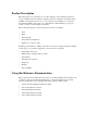
Interface Card Using the Node Port Modem Line (no modem on 8921) Nodal Port VT-100 Control Terminal DB-9 Serial Port Power Bus Edge Connectors Amphenol Connector for WAN Connections Figure 5-7. Component Layout for the INF+M T1E1*8 and INF T1E1*8 Interface Card 5.4 Using the Node Port The Node Port allows the system to report ACO (Alarm Cutoff) alarms to an external system to alert the operator to critical situations.
Model Interface CardNo. Running Card Head User Screens and Settings Interface Designation Interface Card Pin # 1 2 Nodal Port ANO ANC ACOM Amp Amp Common 3 4 5 6 7 GND 8 External Alarm System ANO = Open to ACOM on Alarm ANC = Closed to ACOM on Alarm Figure 5-8. Node Port ACO Alarm Interface Table 5-5.
Interface Card Node_1 | IF Interface Card User Screens and Settings INF+M T1E1x8 Rev A0-0 Ser 01103 |12-31-99 14:33 1 PRIMARY CLOCK EXT RATE EXT FORMAT EXT FRAME int n/a n/a n/a SECONDARY CLK EXT RATE EXT FORMAT EXT FRAME int n/a n/a n/a CURRENT CLK int Save | Undo | Refresh | Time | ACO | proFiles | taBs | Ports | Main Figure 5-9. Typical Interface Card Main Screen The bottom line of this screen shows numerous actions that you can perform from the screen.
Model Interface CardNo. Running Card Head User Screens and Settings Interface 5.5.1.1 Setting the System Date and Time To set the current date and time for the integrated access system, first press “t” in the Interface Card Main Screen to choose the Time action from the bottom line of that screen. The current date and time now appear in the lower left of the screen, in the format MM-DD-YY HH-MM. The MM field (month) is highlighted.
Interface Card Interface Card User Screens and Settings A network clock is the best Primary Clock source. To select this source, set the Primary Clock field to wan, and then specify the WAN link to which the clock source is connected (for example, w1-1 for T1 or E1 link 1 on the WAN card in chassis slot W1). The WAN clock source will be either 1.544 or 2.048 Mbps (T1 or E1 link). This clock must be accurate to within ±50 parts per million (50 x 10-6).
Model Interface CardNo. Running Card Head User Screens and Settings Interface You can set up signaling conversion for all types of voice circuits from the Signaling Conversion Table Screen, which is shown in Figure 5-10. To go to that screen, press “b” in the Interface Card Main Screen (taBs command). You can accept the default bit pattern changes, or you can set a different ABCD signaling bit pattern and insert it in the table.
Interface Card Interface Card User Screens and Settings Table 5-8. Signaling Conversion Table Screen Actions Action Save Undo Refresh Default Main 5.5.3 Function Saves changes to settings. Returns all settings to the last saved state. Redraws the current screen. Returns column to default settings, one column at a time. You must save your changes after using this command. Returns to the Interface Card Main Screen. If changes are made to settings and not saved, your changes will be lost.
Model Interface CardNo. Running Card Head User Screens and Settings Interface 5.5.3.2 Network Priorities All integrated access controllers on the wireless network have equal priorities. Because of this equality, no Controller can interrupt a remote session between another Controller and a control station. This is why the control station always initiates all communication on the RTS network. 5.5.3.3 Intra-Network Communications Integrated access controllers cannot communicate with each other.
Interface Card Interface Card User Screens and Settings Table 5-9. “AT” Commands Used by RTS AT Command Function ATDTxxx ATDTxxxR Establish a user interface connection. Establish an alarm reporting connection. (Connection only lasts for the length of time necessary to upload and display all alarms that are being reported by the system that have not yet been displayed.) ATDTxxxC Establish a current alarm reporting connection.
Model Interface CardNo. Running Card Head User Screens and Settings Interface Node_1 | IF INF+M T1E1x8 VT ui 9.6 8,1,N none PROTOCOL RATE COM CFG HANDSHAKE Rev A0-0 C1 none 9.6 8,1,N none Ser 00000 | 12-31-99 14:33 M ui 2.4 8,1,N none Save | Undo | Refresh | Main Figure 5-12. Typical Ports Screen (INTF+M) This screen shows the Protocol, Rate, Communications, and Handshaking control settings for each port.
Interface Card Interface Card User Screens and Settings For the modem port, choose ui, ui-pr, or none. RATE The transmission rate for the VT (9.6 kbps) and C1 ports when selecting PPPcan be 19.2 kbps. The rate for the M port is always 2.4 kbps. You cannot change these settings. COM CFG The Communication Configuration settings are always 8 data bits, one stop bit, and no parity (8,1,N) for all three ports. You cannot change these settings on any port.
Running Card Head Error Messages Interface 5.6 Model Interface CardNo. Interface Card Error Messages Refer to Appendix B in the System Reference Guide for further information on Error Messages regarding this card. 5.7 Interface Card Troubleshooting 5.7.1 User Interface Problems The Interface card provides the connections from the integrated access system to the external control terminals and/or other network management systems.
Interface Card Interface Card Troubleshooting Note that removal of the Interface card will cause a service disruption on all T1 and E1 WAN links of the system. 5.7.3 WAN Transmission Problems A faulty Interface card could cause T1 and E1 WAN service disruptions, since this card also provides the WAN connections. Electrically, the Interface card resides between the WAN cards and the T1/E1 network.
Running Card Head Troubleshooting Interface 5-22 Model Interface CardNo.
WAN Card Introduction Chapter 6 WAN Card 6.1 Introduction This chapter provides installation, configuration, and troubleshooting information for the Wide-Area Network (WAN) Cards. These include the WAN SINGLE, WAN DUAL, WAN-U DUAL, WAN-R DUAL and WAN-2P ESF LPBK Cards. These designations are marked on the faceplate ejectors of the associated cards. Throughout the remainder of this chapter, these cards are referred to as the WAN SINGLE, WAN DUAL, WAN-U, and WAN-R cards, respectively.
Running Head WAN Card Descriptions 6.2.1.2 Model WAN CardNo. Card External Connectors and Signal Pinouts The WAN SINGLE card does not have any external connectors on its faceplate. 6.2.2 WAN DUAL Card Description (801020 / 801021) The WAN DUAL card connects to two T1 or E1 lines, or to one of each type. It works with only one DSX/CEPT or CSU plug-in module if the WAN port without either module remains in the standby state. However, a CGA-Red alarm will be generated for that port. 6.2.2.
WAN Card 6.2.4.1 WAN Card Descriptions Card Jumper/Switch Settings The WAN-R card does not have any jumpers or switches on its motherboard. 6.2.4.2 Card External Connectors and Signal Pinouts The WAN-R card does not have any external connectors on its faceplate. 6.2.5 WAN Card with ESF Loopback Description (801560) The WAN card with ESF Loopback is able to detect ESF data link codewords for line and payload, activate and deactivate commands.
Model WAN CardNo. Running Head WAN Card Descriptions 6.2.6.2 Module Installation For DSX or CEPT operation, you must install one of these modules on the associated WAN card before inserting those cards into the system chassis. Figure 6-1 shows the locations of the DSX/CEPT modules on a WAN card. One module is required per WAN port. If your system has a T1 link (DSX) and an E1 link (CEPT), you will need two DSX/CEPT modules. First, install a DSX/CEPT module in the slot reserved for WAN port 1-1.
WAN Card WAN Card Descriptions Jumpers set to E1-75 Figure 6-2. DSX/CEPT Module Jumpers (E1 75 Ohm) Jumpers set to E1-120 Figure 6-3.
Model WAN CardNo. Running Head WAN Card Descriptions Jumpers set to T1 Figure 6-4. DSX/CEPT Module Jumpers (T1) Jumpers set to T1 Figure 6-5.
WAN Card WAN Card Descriptions Jumpers set to E1-75 Figure 6-6. DSX/CEPT Module Jumpers (E1 75 Ohm) Jumpers set to E1-120 Figure 6-7. DSX/CEPT Module Jumpers (E1 120 Ohms) 6.2.6.4 Revision E1+ Module The DSX/CEPT Revision E1+ module (Figure 6-8 and Figure 6-9) provides jumper settings for impedance compensation. These modules support either T1 or E1 operation, with either 75 ohms or 120 ohms for an E1 interface.
Model WAN CardNo. Running Head WAN Card Descriptions Jumpers Figure 6-8. DSX/CEPT Revision E+ Module Jumpers Figure 6-9. Module End View Figure 6-10. DSX T1 Operation Jumper Settings Figure 6-11. 75-Ohm E1 Jumper Settings Figure 6-12.
WAN Card 6.2.6.5 WAN Card Descriptions Revision A1 Through D1 Modules The DSX/CEPT Revision A1 through D1 modules (Figure 6-13 and Figure 6-17) provide jumper settings for impedance compensation. These modules support T1, 75-ohm E1, or 120-ohm E1 operation. To configure this module, set the jumper positions on the pins according to Figure 6-15 through Figure 6-17. The module is shipped for T1 DSX operation, as shown in Figure 6-15. Jumpers Figure 6-13.
Model WAN CardNo. Running Head WAN Card Descriptions Figure 6-17. 120-Ohm E1 Jumper Settings When installing the 811 CSU/DSX module on the 8000 WAN or 8010 WAN, there are situations in which the plastic standoffs do not allow the module to seat correctly on the WAN board (see Figure 6-18). TOP VIEW HOLES for Plastic Standoffs Side View Remove all plastic standoffs Figure 6-18.
WAN Card WAN Card Descriptions When assembling and installing the module on the WAN card, it is our advice that the plastic standoffs be removed to eliminate the possibility of errors on the associated T1 or E1 lines. For this reason, the plastic standoffs are no longer being supplied by the manufacturer for new WAN modules. 6.2.6.
Running Head WAN Card Descriptions Model WAN CardNo. For 75-ohm unbalanced E1, set the adapter panel jumpers to UNBAL in one location only, and set them to BAL in all other cases. When multiple DSX/CEPT modules with jumpers are installed, the unbalanced jumper should be set on the module closest to the E1 line. When the adapter panel is present, it is considered the unit closest to the E1 line.
WAN Card 6.2.9 WAN Card User Screens and Settings Installing the WAN Cards After installing the proper modules on the WAN cards, insert the WAN cards into the system chassis. Each system can have up to four WAN cards, which go into slots W1 through W4. For a system with redundant WAN cards, always insert a WAN-R card into slot W4. If you install the WAN-R card into any other WAN card slot, it will work as a regular WAN card (not as a redundant card).
Model WAN CardNo. Running Head WAN Card User Screens and Settings The headers of all WAN card screens show the types of modules installed on those cards. The above example shows a WAN DUAL card with a CSU module on port 1 and a DSX/CEPT module configured for T1 DSX operation on port 2. This card is installed in WAN card slot W1 of the system. Its screen header designation is therefore W1 CSU+DSX. The DSX/CEPT and HDSL modules also have identical parameters.
WAN Card WAN Card User Screens and Settings Table 6-3. T1 CSU and DSX Option Settings and Defaults Parameter STATE MODE FORMAT LINE CODE PULSE LINE LEN SLIP LIM AIS/ALM LINE LB LOCAL LB CH LB LB ADDR LB GEN LB DET ESF/NMS RP EER THRHD RDNT RULES GROUP User Options stdby actv term d-i xcon d4 esf slc96 slcd4 ami b8zs n/a trnsp z15s 0 7.5 15.
Running Head WAN Card User Screens and Settings Model WAN CardNo. STATE In the standby state, the WAN port is electrically disconnected from the network. Set this field to stdby (standby) while configuring WAN links, and then change it to actv (active) when starting normal operations. If the WAN is in loopback due to a command from a remote device, the loopback will be dropped if you switch to stdby.
WAN Card WAN Card User Screens and Settings must provide 1s density). If the Line Code parameter for the CSU is b8zs, the Pulse option will default to trnsp. If the WAN link is equipped with a DSX plug-in module, this option will automatically default to n/a. LINE LEN The Line Length setting adjusts the T1 power level to compensate for the distance the signal must travel before it reaches the first T1 line repeater or other device. For a DSX interface, the options are 133, 266, 399, 533, and 655 feet.
Running Head WAN Card User Screens and Settings Model WAN CardNo. AIS/ALM The AIS/ALM (Alarm Indication Signal/Alarm) setting allows you to specify the type of “keep-alive” signal the system will generate on one T1/E1 link if the other one fails. The AIS/ALM setting depends on the framing Format selected for this WAN card. Table 6-5 shows the AIS/ALM settings for cross-connect systems. Table 6-5.
WAN Card WAN Card User Screens and Settings Network Line Loopback T1/E1 W AN Card Local Loopback PCM Bus Figure 6-21. Line and Local Loopbacks LOCAL LB The Local Loopback setting allows you to loop the full T1/E1 line back toward the CPE, as shown in Figure 6-21. This loopback also continues sending CPE data toward the network. Choosing on allows you to test the local system. Choosing off disables the loopback and restores the normal signal path in both directions.
Model WAN CardNo. Running Head WAN Card User Screens and Settings Network T1/E1 W AN Card PCM Bus Figure 6-22. DS0 Time Slot Loopback LB ADDR The Loopback Address setting, when used in conjunction with the Channel Loopback setting, specifies which time slot will be looped back. Only one time slot may be looped back at a time for each T1 link. The options for T1 lines are 1 to 24. For E1 lines, the options are 1 to 31.
WAN Card WAN Card User Screens and Settings LB DET This option allows the card to detect DS1 channel, and ANSI T1.403 (8015 WAN only) loopbacks. When set to off, no T1 loopbacks can be detected. When set to on, T1 loopbacks will be detected and maintained until a loop down is detected. The with/time-out (w/to) is the same as on except that if no loop down is detected after 10 minutes, the loopback will self-termiante. Currently WAN card with ESF Loopback is the only card that detects ANSI T1.
Model WAN CardNo. Running Head WAN Card User Screens and Settings GROUP The Group setting identifies a method of link-fail alarm propagation from upstream trunks to downstream tributaries when the system is configured for alarm transcoding. The selection of a group is a two-step process. After identifying the group number (1 to 4), select the secondary group (A [child group], B [child group] or C [parent group]). Figure 6-23 shows two system units with "parent-child" groupings.
WAN Card WAN Card User Screens and Settings 4. SYS 1(C) sends an alarm message to SYS 2 (C1), telling it that W1-1(A) is either in a CGA_RED or AIS alarm. 5. SYS 2 sets the transmit leg of W3-1(A1) into AIS (CGA_RED). Device 2 detects this condition and knows not to use W3-1(A1). When the original failure is corrected, the alarm is also cleared for downstream tributaries. 6.3.2 E1 CEPT and HDSL Settings Figure 6-24 shows the WAN Card Main Screen for E1 operation.
Model WAN CardNo. Running Head WAN Card User Screens and Settings Table 6-6. CEPT/HDSL Screen Actions Action Save Undo Refresh Xcon Perf Farstat Test sWitch Hdsl Main Function Saves changes to settings. Returns all settings to the last saved state. Updates certain time-related information fields that are not automatically updated (i.e., performance and test data). Shows the time slot cross-connect map for each WAN port. Brings up the Performance Data Screen.
WAN Card WAN Card User Screens and Settings 5. Selection of GROUP is a two-step process. After identifying the group number (1-4), the user must select the secondary group (A, B or C). STATE In the standby state, the WAN port is electrically disconnected from the external network. Set State setting to stdby (standby) when setting up your WAN links, then changes it to actv (active) when starting normal operations. MODE In cross-connect systems, Mode automatically defaults to xcon.
Running Head WAN Card User Screens and Settings Model WAN CardNo. LOCAL LB The Loopback setting controls looping of the full E1 line back to the PCM bus. The options are off and on. When on, this setting allows testing of local equipment. The system generates a "Keep Alive–Type 1" pattern on the E1 line. CH LB The Channel Loopback setting allows you to place individual DS0 channels in loopback toward the PCM bus.
WAN Card WAN Card User Screens and Settings EER THRHD The Excessive Error Rate Threshold selects the error rate, which an alarm is declared. This setting interacts with the EER setting in the Alarm Filters of your system. The options are 10e-4 through 10e-9, or none. RDNT RULES The selection of Redundancy Rules will define the method of determining what event will trigger a WAN port to switch to its redundant mate. The options are none, OOS, or CGA.
Model WAN CardNo.
WAN Card 6.3.4 WAN Card User Screens and Settings Performance Data All WAN cards gather performance data. The performance data for a T1 or E1 line is viewed by typing “p” in the WAN Card Main Screen, to invoke the Perf command. Performance data is accumulated for 15-minute increments that include the current period and the previous 96 periods (24 hours), which are accessed via the pgUp and pgDn commands of the Main Screen.
Model WAN CardNo. Running Head WAN Card User Screens and Settings Table 6-8 lists the actions available from the Performance Data Screen. Table 6-8. Performance Data Screen Actions Action Refresh pgUp pgDn uSerregs Networkregs Clearregs Main Function Because statistics are not calculated in real time, the Refresh command must be used to update the screen with new information. Pages through the performance statistics for the current 15 minute period and periods 96-1.
WAN Card WAN Card User Screens and Settings LOFC The Loss of Frame Count (LOFC) is the number of times a Loss Of Frame (LOF) is declared. An LOF is declared after 2.5 seconds of a continuous Loss Of Synchronization (LOS) or Out-Of-Frame (OOF) condition. The LOF is cleared after no more than 15 consecutive seconds without another LOS or OOF. SLIP A Slipped Second is any second that contains one or more Controlled Slips.
Model WAN CardNo. Running Head WAN Card User Screens and Settings Node_1 | W1 H_E1+H_E1 Rev A1-0 Ser 00101 Unit 1 AT&T FAREND STATISTICS NETWORK REGISTERS CUR 01 02 03 04 05 06 07 08 09 10 11 12 TOTAL ES 0 ***** ***** ***** ***** ***** ***** ***** ***** ***** ***** ***** ***** 0 UAS 0 ***** ***** ***** ***** ***** ***** ***** ***** ***** ***** ***** ***** 0 Retrieving message.
WAN Card WAN Card User Screens and Settings ES An Errored Second (ES) is a second with one or more CRC-6 (ESF) or BPV (D4/D-Frame) errors, one or more OOFs, or one or more Controlled Slips. UAS An Unavailable Second (UAS) is any second during which service is unavailable. An unavailable signal state is declared after ten consecutive Severely Errored Seconds (SESs) are logged. An unavailable state is cleared after ten consecutive non-Severely Errored Seconds are logged.
Model WAN CardNo. Running Head WAN Card User Screens and Settings Node_1 BERT SYNC BE ES SES CSES OSS BER ELAP LB STATE | W1 CEPT+CEPT CEPT n/a no 0 0 0 0 0 0.0e+1 0 llb Rev A6-2 Ser 00101 | 12-31-99 14:33 CEPT n/a no 0 0 0 0 0 0.0e+1 0 plb Save | Undo | Refresh | InsertErr | Clear | Main Figure 6-29. Typical WAN Card Test Screen Table 6-10. Test Screen Actions Action Save Undo Refresh Insert Err Clear Main Function Saves changes to settings. Returns all settings to the last saved state.
WAN Card WAN Card User Screens and Settings Notes: 1. The lp-up (loop-up) and lp-dn (loop down) codes are not supported for CEPT or HDSL WANs. Turning any of these tests on or off will cause a temporary interruption of data transmission on the DS0 time slots as well as on the FDL bit of the corresponding port. BERT The Bit Error Rate Tester (BERT) sends a data pattern and measures the bit error rate (BER) on the selected WAN port.
Running Head WAN Card User Screens and Settings Model WAN CardNo. CSES The Consecutive Severely Errored Seconds (CSES) field is triggered by the occurrence of ten consecutive Severely Errored Seconds. Once triggered, the CSES field will increment (by one) for each elapsed second until the system logs ten consecutive non-Severely Errored Seconds. Since this is an information-only field, there are no user-selectable parameters.
WAN Card Node_1 WAN Card User Screens and Settings | W1 H_E1+H_E1 Rev A0-0 Ser 00101 | 12-31-99 14:33 TRAIN MODE LOOP 1 ltu off 2 ntu off LOSS LP1 LOSS LP2 QLTY LP 1 QLTY LP 2 LB STATUS 0 0 loss 10 none 0 0 loss 10 none Save | Undo | Refresh | Perf | Main Figure 6-30. Typical HDSL Screen Table 6-12. HDSL Screen Actions Action Function Save Undo Refresh Perf Main Saves changes to settings. Returns all settings to the last saved state. Redraws the screen.
Running Head WAN Card User Screens and Settings Model WAN CardNo. TRAIN MODE This parameter determines the master/slave relationship between the units. The setting for the central office master unit is ltu (default). Remote slave units should be set to ntu. LOOP This parameter sets loopbacks on the remote unit. Selecting r-loc will cause the remote link to loop back to the PCM buses of the remote unit. Selecting r-net will cause the remote link to loop back to the network. The default is off.
WAN Card Node_1 Unit 1 CUR 01 02 03 04 05 06 07 08 09 10 11 12 TOTAL WAN Card User Screens and Settings | W1 H_E1+H_E1 Rev A0-0 Ser 00101 HDSL Performance (15 Min Interval) *Local* LOOP 1 LOOP 2 ES SES UAS ES SES 0 0 0 0 0 0 0 0 0 0 0 0 0 0 0 0 0 0 0 0 0 0 0 0 0 0 0 0 0 0 0 0 0 0 0 0 0 0 0 0 0 0 0 0 0 0 0 0 0 0 0 0 0 0 0 0 0 0 0 0 0 0 0 0 0 0 0 0 0 0 12-31-99 14:33 UAS 0 0 0 0 0 0 0 0 0 0 0 0 0 0 STATUS T..T.. ...... ...... ...... ...... ...... ...... ...... ...... ...... ...... ...... ...... .....
Model WAN CardNo. Running Head WAN Card User Screens and Settings Node_1 Unit 1 CUR 01 02 03 04 05 06 07 TOTAL | W1 H_E1+H_E1 Rev A0-0 Ser 00101 | HDSL Performance (24 Hour Interval) *Remote* LOOP 1 LOOP 2 ES SES UAS ES SES 0 0 0 0 0 0 0 0 0 0 0 0 0 0 0 0 0 0 0 0 0 0 0 0 0 0 0 0 0 0 0 0 0 0 0 0 0 0 0 0 0 0 0 0 0 12-31-99 14:33 UAS 0 0 0 0 0 0 0 0 0 STATUS T..T.. ...... ...... ...... ...... ...... ...... ...... ......
WAN Card PARS Screen Table 6-14. HDSL Performance Data Screen Actions Action Refresh Clearregs 24 Hr 15 mIn REmote Local PgUp pgDn Main Function Redraws the screen and updates information. Clears the user registers and starts over. Toggles to 24-hour interval monitoring. Toggles to 15-minute interval monitoring. Toggles to remote loop monitoring. Toggles to local loop monitoring. Scrolls up through historical intervals (n/a for 24 hour intervals). Scrolls down through historical intervals.
Model WAN CardNo. Running Head PARS Screen Node_1 | W1 CEPT+CEPT Rev A6-2 Ser 00101 | 12-31-99 14:33 1 yes PARS MODE 0 1 2 3 4 5 6 7 8 9 X 1 1 1 1 1 1 1 1 1 1 2 2 2 2 2 0 1 2 3 4 5 6 7 8 9 0 1 2 3 4 Save | Undo | Refresh | sIgnaling | Main Figure 6-33. Typical T1 WAN PARS Screen Table 6-15. T1 WAN PARS Screen Actions Action Save Undo Refresh sIgnaling Main Function Saves changes to settings. Returns all settings to the last saved state.
WAN Card Node_1 PARS Screen | W1 CEPT+CEPT Rev A6-2 Ser 00101 | 12-31-99 PARS MODE 1 yes 0 1 2 3 4 5 6 7 8 9 F X 1 1 1 1 1 1 1 1 1 1 2 2 2 2 2 2 2 2 2 2 3 3 0 1 2 3 4 5 6 7 8 9 0 1 2 3 4 5 6 7 8 9 0 1 S 14:33 Save | Undo | Refresh | sIgnaling | Main Figure 6-34. Typical E1 WAN PARS Screen Figure 6-34 shows an E1 WAN PARS screen. For E1 WANs, signaling is always carried on time slot #16 as indicated by the “S”.
Model WAN CardNo.
WAN Card Node_1 PARS Screen | W1 CIRCUIT_ID wp_circuit pars_circuit W/U w1-1 u3-01 CSU+CSU TS/BW 24*64 01*56 Rev A6-2 TEST off off Ser 00101 W/U w1-2 w1-1 TS/BW 24*64 01*56 | 12-31-99 TEST off off TYPE v d 14:33 TC CNV n/a no n/a n/a Bcast | uPdate | dElete | pgUp | pgDn | Main Figure 6-36. System (Main) Cross-Connect Screen in PARS MODE Figure 6-36 shows the System (Main) cross-connect screen after PARS MODE has been selected. This screen shows the result of the “View all” menu selection.
Running Head PARS Screen Model WAN CardNo. 4. Once a primary WAN is assigned to PARS mode, the secondary WAN will be assigned to APRS by the system and will not be available to the user. Nothing can be terminated on a secondary WAN after PARS MODE is selected. 5. Physcial connections are always made from the secondary WAN to the primary WAN of the adjacent node. 6. User cards will be terminated normally on the primary WAN. 7.
WAN Card PARS Screen IAD 1 IAD 2 IAD 5 IAD 3 IAD 4 Figure 6-37.
Model WAN CardNo. Running Head PARS Screen 6.4.3 One Link is Lost If the link from IAD 1 to IAD 2 fails, then the traffic is rerouted as illustrated in Figure 6-38. IAD 1 IAD 2 IAD 5 IAD 3 IAD 4 Figure 6-38.
WAN Card 6.4.4 PARS Screen Two Links are Lost, One IAD is Isolated from the Ring If the link from IAD 1 to IAD 2, and the link from IAD 2 to IAD 3 fial, then the traffic is rerouted as illustrated in Figure 6-39. IAD 1 IAD 2 IAD 3 IAD 5 IAD 4 Figure 6-39.
Model WAN CardNo. Running Head PARS Screen 6.4.5 Two Links are Lost, Two IADs are Separated from the Ring If the link from IAD 1 to IAD 2, and the link from IAD 4 and IAD 5 fail, then the traffic is rerouted as illustrated in Figure 6-40. IAD 1 IAD 2 Primary Ring Secondary Ring IAD 3 IAD 5 IAD 4 Figure 6-40. Traffic Flow when two connected IADs are separated from the Ring 6.4.
WAN Card 6.4.7 PARS Screen Normal Operation - No Link Failure Any of the WAN lines in a cross-connect integrated access device can be assigned to PARS mode. Once a WAN (W1-1 for example) is assigned to PARS mode, the other WAN of that card (i.e. W1-2) will be assigned to PARS by the system and will not be available to the user. The user assigned WAN will become primary and the system assigned WAN will become the secondary.
Model WAN CardNo. Running Head PARS Screen HSU, FXS, E&M or SRU RX W1-1 TX TX W1-2 RX Figure 6-42. User card Termination on PARS WAN Node 1 HSU Node 4 W1-1 W1-1 cross-connect W1-2 W1-2 HSU cross-connect HSU cross-connect W1-2 W1-1 W1-2 Node 2 HSU cross-connect Node 3 W1-1 Figure 6-43.
WAN Card PARS Screen A four node configuration operating in PARS mode is illustrated in Figure 6-43. In this configuration one user port per node is used for the purpose of illustration. In node one the transmit of all 24 time slots of W1-1 are cross-connected to the receive of all 24 time slots of W1-2. The receive of 23 time slots of W1-1 are cross-connected to the transmit of 23 time slots of W1-2.
Model WAN CardNo. Running Head PARS Screen HSU, FXS, E&M or SRU Ports 1 2 3 HSU, FXS, E&M or SRU Ports 1 2 TS1 3 TS1 RX RX W1-1 W2-1 TX TX W1-2 TX TX RX W2-2 RX Figure 6-45. PARS Rerouting (two nodes) Figure 6-45 shows detail of PARS mode for two nodes with the link between adjacent nodes broken. Time slots have been rerouted and any User card terminated on the failed WAN has been assigned to the WAN with the unbroken link.
WAN Card 6.5 WAN Card Error Messages WAN Card Error Messages Refer to Appendix B in the System Reference Guide for further information on Error Messages regarding this card. 6.6 WAN Card Troubleshooting The WAN card (or a T1 or E1 port on it) may be faulty if a CGA-Red alarm is in progress on either port of the card. This alarm occurs if the incoming network signal is lost, or if the WAN port is out of frame with that signal. To isolate the trouble, proceed as follows: 1.
Running Head WAN Card Troubleshooting 6-56 Model WAN CardNo.
Appendix A System Specifications A.1 FCC Requirements Table A-1. FCC Registration Information - Part 1 Reg. Status M M Reg. MTS/WATS Interfaces 02LS2 02GS-2 02LS2 Model # FXO 2W*8-6 FXO 2W*8-6 INF+M T1E1 Ringer Equiv. Number 0.4B (ac), 0.0 (dc) 0.4B (ac), 0.0 (dc) 0.8B (ac), 0.0 (dc) SOC ------------- Network USOC RJ11X RJ11X RJ11X Canadian Jacks CA11X CA11X CA11X Table A-2. FCC Registration Information - Part 2 Reg. Reg. Reg. Reg. Reg. Reg. Reg. Reg. Reg. Reg. Reg.
Model No. Running Head Table A-3. FCC Registration Information - Part 3 Reg. Digital Interfaces Model # Reg. 04DU9-BN WAN SINGLE, WAN DUAL* Reg. 04DU9-DN WAN SINGLE, WAN DUAL* Reg. 04DU9-1KN WAN SINGLE, WAN DUAL* Reg. 04DU9-1SN WAN SINGLE, WAN DUAL* Reg. 04DU9-1ZN WAN SINGLE, WAN DUAL* Reg. 04DU9-BN WAN SINGLE, WAN DUAL** Reg. 04DU9-DN WAN SINGLE, WAN DUAL** Reg. 04DU9-1KN WAN SINGLE, WAN DUAL** Reg.
Table A-5. System Electrical and Environmental Requirements Parameter AC Power DC Power (-48 VDC) DC Power (+24 VDC) Power consumption Operating temperature Storage temperature Humidity Requirement 100 to 240 VAC, 50 to 60 Hz -42 to -56 VDC +20 to +28 VDC 125 Watts (typical), 500 Watts (maximum) 0°C to 50°C (32°F to 122°F) -20°C to 80°C (-4°F to +176°F) 0% to 95% relative humidity, noncondensing Table A-6 lists the cards that require pre-installation setup.
Model No. Running Head Table A-7.
A.4 Power Requirements Table A-8. Power Supply Options Compatibility Power Sources AC Power Supply -48V Power Supply -48V Converters Ringing Gen. +24V Power Supply External -48 VDC Power External Ringing Generator AC Power Supply -48V Power Supply -48V Converters --- yes yes yes yes yes yes yes --- no yes no yes yes yes no --- yes no no yes Ringing Gen.
Model No. Running Head Table A-9. Replacement Fuses for the External Talk Battery Supply Manufacturer Little Fuse Bussman Part Number 218.005 GDC-5 Table A-10. AC Power Supply Specifications Parameter Rating Output Power, Continuous Output Power, Peak (60 seconds) Input Current (maximum) Source Input Current (maximum) Inrush Surge Current Input Frequency Efficiency 50 Watts 70 Watts (10% duty cycle) 1.7A at 120 VAC, 60Hz full-rated output load 3A Maximum 3.
Table A-13. +24 VDC Power Supply Specifications Parameter Input Power Output Power, Continuous Input Voltage Efficiency Rating +24V 50 Watts maximum +18 to 35VDC 83% Table A-14.
Model No. Running Head A.5 Alarm Filter Requirements Table A-15.
A.6 Physical Specifications and Power Consumption Table A-16. Physical Specifications and Power Consumption Item Height Common Equipment Model inches Width cm inches Depth cm inches Weight cm lb Power Kg Watt BTU/hr System Unit System Unit System Unit 8916 8918 8919 9.0 9.0 9.0 22.9 22.9 22.9 17 17 17 43.2 43.2 43.2 9.13 15.38 9.13 23.2 39.0 23.2 8.5 11.0 11.0 3.96 5.0 5.
Model No. Running Head FXO Card FXO Card FXO Coin Card 8138 8139 8159 8.0 8.0 8.0 20.3 20.3 20.3 .94 .94 .94 2.4 2.4 2.4 7.5 7.5 7.5 19.0 19.0 19.0 1.25 1.25 1.0 .57 .57 .45 7 7 9.7 23.9 23.9 33.12 8202 8203 8212 8213 8214 8215 8220 8228 8231 8241 8246 8249 8254 8260 8261 8262 8.0 8.0 8.0 8.0 8.0 8.0 8.0 8.0 8.0 8.0 8.0 8.0 8.0 8.0 8.0 8.0 20.3 20.3 20.3 20.3 20.3 20.3 20.3 20.3 20.3 20.3 20.3 20.3 20.3 20.3 20.3 20.3 .94 .94 .94 .94 .94 .94 .94 .94 .94 .94 .94 .94 .94 .94 .94 .94 2.4 2.
A.7 Part Number / Acronym Table The following table details the part number of each card or peripheral listed in this guide.
Running Head A-12 Model No.
Appendix B Error Messages B.1 Introduction This chapter lists the integrated access system error messages. One of these messages may appear at the bottom of the screen when you enter a command, indicating that the system did not perform the requested action. This condition may have been caused by an operator error, absence of a card in the system, or other condition. If an error message appears, take the appropriate corrective action. For convenience, the system error messages are listed alphabetically.
Model No. Running Head All available PVCs are already taken. The number of PVCs available on the FRAD Card Main Screen has been exceeded by the number of PVCs assigned on the PVC Screen. Assign a number of PVCs on the PVC Screen that is lower than the quantity chosen in the Main Screen. All blank prt repot. You chose the empty option setting for all four elements of the Print Alarm on the Interface Card. This combination of settings is invalid and cannot be saved.
Cannot define any more PVC connections. The maximum number of PVC connections has been reached. Cannot define any more XCON circuits. The maximum number of cross-connect circuits is 99. Can NOT delete circuit while test is active. You must end the test in progress before deleting the circuit. Cannot do it in Viewer mode. You are logged in under the Viewer password, but that level of access does not allow you to perform the desired operation.
Running Head Model No. Cannot use the same TS on different WAN. You cannot assign an SRU card port to the same time slot on different WAN ports. Can’t define any more IP entries. The maximum number of IP entries has been reached. Can’t initialize modem. The Interface card modem was not initialized. Card already installed. You cannot use the Configuration option on an occupied chassis slot. Card does not respond. The card is not responding to your commands.
Combined ADPCM rate must equal 64K. You cannot assign a 40 kbps and a 32 kbps channel to the same ADPCM 64 kbps engine. The only valid combinations are 40 kbps + 24 kbps, 32 kbps + 32 kbps, and 24 kbps + 40 kbps. Command rejected. Switch in progress. The command was not executed because a redundancy switch is in progress. Config. changes must be made from primary WAN. You cannot make configuration changes to a redundant WAN port. This is allowed only on primary WAN ports.
Running Head Model No. Each WAN can have only one d-chan. You cannot assign two D-channels to the same WAN port. Empty field is not allowed. You cannot assign a blank password on the CPU Card Main Screen. Always enter alphanumeric characters. Empty slot. You cannot access the card or associated screen because it is not plugged into the chassis. Engine pair must have same ADPCM WAN and TS. You must assign each pair of ADPCM engines (1-2, 3-4, 5-6, etc.) to the same WAN port and time slot.
Group already taken. This group is already assigned. Illegal IP Mask. The IP netmask number you chose is invalid. Invalid character in Node Id. The only valid characters for a Node ID are alphanumeric characters and the underscore. Invalid date/time format. You have entered an invalid date or time. Invalid Dlci value. The DLCI number you chose is invalid. Invalid endpoint name. The endpoint name you chose is invalid. Invalid IP address. The IP address you chose is invalid. Invalid IP netmask.
Running Head Model No. Invalid password for this command. You cannot use the debug command from the System Test and Debug Screen without the proper password authorization. Invalid secondary clock format. You cannot assign an external clock source as the secondary system clock. Invalid SR TS. You cannot assign an SRU card subrate port to a WAN time slot that does not have enough room on the subrate time slot for that much bandwidth.
Local LB & Test Pattern can’t be ON together. You cannot perform a loopback with a test pattern applied, and you cannot apply a test pattern if a loopback is active. MAJ EC is not available with RATE> 9.6. You cannot use majority-vote error correction on an SRU card port with a Rate higher than 9.6 kbps. Use bch error correction instead, or disable error correction. Mode cannot be changed when any ts are allocated.
Model No. Running Head N392 must be less than or equal to N393. N392 determines the amount of errors that will be tolerated during the amount of events assigned in N393. FRAD rules require that N392 be less than or equal to N393. No changes for selected switch. When connected to an ISDN office switch, you cannot change the status of a B-channel. No changes while BERT is running. You cannot change the port configuration while Bit Error Rate Testing is active.
No more than two WANs in BERT test are allowed. You can place only two WAN ports in the BERT test mode simultaneously. No second net-lb allowed when bw = 115.2 kbps. You cannot activate more than one network loopback at a time on an SRU card port. No timeslot(s) specified. You cannot activate a user card that doesn’t have any WAN time slots assigned to it. No Voice Compress. WAN card using ALL resources. No ADPCM card is currently available for voice compression. Not applicable for S/T card.
Running Head Model No. Only broadcast.data type can be controlled. You cannot update or delete a regular cross-connect circuit from the Cross-Connect Broadcast Screen. Only broadcast/data type can be controlled. You cannot update or delete a regular cross-connect circuit from the Cross-Connect Broadcast Screen. Only network or data type can be broadcasted. You cannot broadcast a Broadcast circuit from the Cross-Connect Broadcast Screen. Only one ADPCM redundant in the system.
Performance statistics is not available in slc96. You cannot obtain performance statistics for a WAN port in the slc96 mode. Performance statistics not available. You cannot obtain performance statistics for this card or port. Phone number must be unique. The primary phone number on an HSU card must be unique. Port already configured for Remote Terminal. This port is already configured for use with a remote terminal. Port is in use. You cannot make any changes to an active port. Port is not active.
Running Head Model No. Profile has to be loaded first. You cannot use the Dial command in the HSU Card Main Screen without first loading a call profile. Profile Id was not found. Upon using the Load command in the HSU Card Main Screen, you requested a non-existing call profile from the Interface card. RATE = 19.2 must have DATA = 8 for adpcm or hlink. If you set the SRU card port rate to 19.2 kbps, you also must set the number of data bits for that port to 8.
Restricted field. You cannot access the Superuser password field on the CPU Card Main Screen. This password is factory-assigned. Selected ADPCM can be primary only. The current ADPCM card cannot be a redundant card. Selected circuit is not primary. The current circuit is redundant, not a primary circuit. Selected circuit is under the test already. The current circuit is already being tested. Service table is currently used by profile.
Running Head Model No. SR TS overlapping. The subrate circuit assigned does not allow enough space for a previously assigned circuit on the same subrate time slot. For example, if you have a 19.2 kbps device on subrate time slot 1 in b-5 framing, you cannot assign another 19.2 kbps circuit to subrate time slot 2, because the circuit on 1 actually occupies subrate time slots 1 and 2. You must therefore assign that other circuit to subrate time slot 3 or 4. Switch request sent to card.
TS 16 cannot be used with v&s. You cannot assign a voice circuit with signaling to time slot 16 of an E1 WAN port. TS 16 is already in use. You cannot assign time slot 16 of a CEPT E1 WAN port programmed for cas. TS Connection must be specified. You must specify a time slot connection for the WAN circuit. TS(s) cannot be allocated. You cannot assign a voice cross-connect to time slot 16 of a CEPT E1 WAN port. Unit controlled by FEC. The user card is controlled by forward error correction.
Running Head B-18 Model No.
Appendix C Glossary C.1 Introduction This Appendix lists the glossary of terms used in the telecommunications industry today. AAL ATM Adaption Layer ABCD bits The bits that carry signaling information over a T1 or E1 line. ABR Available Bit Rate ACAMI Alternate Channel AMI, transmitting data on every other DS0 in a DS1 to ensure ones-density. ACO Alarm Cutoff ADPCM Adaptive Differential Pulse Code Modulation ADPCM Card A resource card used to compress voice or subrate data on a DS0.
Model No. Running Head AIS Alarm Indication Signal AIM ATM Inverse Multiplexer a-law E1 companding standard used in the conversion between analog and digital signals in PCM systems. AMI Alternate Mark Inversion, a line coding format for T1 lines.
BECN Backward Explicit Congestion Notification BER Bit Error Rate, the number of errored bits divided by the total number of bits. BERT Bit Error Rate Tester bit Contraction of the words "binary" and "digit." bps Bits per second BRI Basic Rate Interface, (2B+D) in ISDN CAS Channel-Associated Signaling, a means of conveying voice-circuit signaling over an E1 line.
Running Head Model No. CCS Common Channel Signaling CEP Connection End Point CEPT Conference on European Posts and Telecommunications, a European standards organization. CES Circuit Emulation Service CGA Carrier Group Alarm, a condition that results from a network failure. Forces all voice circuits off-hook or on-hook until the alarm-causing condition is cleared and the CGA ends. CLUE Customer-Located Equipment clear channel A DS0 channel without formatting restrictions (i.e.
companding Non-linear reduction of a signal, usually compressing the larger signal values CRC Cyclic Redundancy Check CRC-4 CRC using four check bits CRC-6 CRC using six check bits CSA Carrier Serving Area CSC Common Signaling Channel CSU Channel Service Unit, an interface to a T1 line that terminates the local loop. CTE Channel Terminating Equipment (Network) CTS Clear To Send, a lead on an interface indicating that the DCE is ready to receive data. D4 A common T1 framing format, consisting of 12 frames.
Running Head Model No. DCE Data Communications Equipment DCS Digital Cross-connect System D-channel Full-duplex, 16 kbps BRI channel or 64 kbps PRI ISDN channel. DDS Digital Data Service d/i Drop and Insert, one of the modes of operation for the WAN card. DID Direct Inward Dialing DLC Digital Loop Carrier DLCI Data Link Connection Identifier DMA Direct Memory Access DPO Dial-Pulse Originating DPT Dial-Pulse Terminating DS0 Digital Signal - Zero, the standard bandwidth for digitized voice channels.
DS0–A Strategy for mapping a single low-speed data circuit to a single DS0. DS0–B Strategy for multiplexing two or more DS0-A low-speed data circuits onto a single DS0 (e.g., 5x9.6kbps, 10x4.8kbps or 20x2.4kbps). DS0–DP Card Digital Signal Zero–Dataport Card (one of the data cards for this system). DSL Digital Subscriber Line DSR Data Set Ready DSX Digital Signal Cross-connect DTE Data Terminal Equipment DTR Data Terminal Ready DX Duplex Signaling E1 Digital 2.
Running Head Model No. EPROM Electronic Programmable Read-Only Memory, stores firmware on plug-in modules of the system. ESF Extended Superframe (24-frame sequence for a T1 line; consists of two superframes) ESS Electronic Switching System E&M Earth and Magnetic, or recEive and transMit. The signaling leads on inter-switch voice connections. E&M Card An E&M voice card for this system. F4 Four-frame multiframe structure used in T1 signals.
FRAD Frame Relay Assembler/Disassembler, a card used in this system. FRS Frame Relay Server, a card used in this system. FS Frame Signaling bits (T1 line). FT Frame Terminal bits (T1 line) FUNI Frame User Network Interface FX Foreign Exchange, a line that goes from a CO or PBX beyond the PBX or the CO’s normal service area. FXO Foreign Exchange - Office, performs analog to digital and digital to analog transmission at the CO.
Model No. Running Head HDB3 High-Density Bipolar Order of 3, three-zero maximum coding for E1 lines. Provides a fourth zero violation for data bytes. HDLC High-Level Data Link Control (bit-oriented protocol) HDSL High-bit rate Digital Subscriber Line hlink A proprietary format for subrate data when using the ADPCM card. HSU Card High-Speed Unit Card (one of the data cards for this system).
ITU International Telecommunications Union (previously known as CCITT [Consultative Committee for International Telegraph and Telephone]) ITU-T International Telecommunications Union, Technical sector IXC Interexchange Carrier (also called IEC) LAN Local Area Network LANE LAN Emulation loopback Path for returning a signal back to the point of origin for circuit testing modem Contraction of the words “modulator” and “demodulator” MRD Manual Ringdown MSP Maintenance Service Provider mu-law T1 companding stand
Running Head Model No. NNI Network Node Interface NOS No-Signal Alarm NRZ Non-Return-to-Zero signal format NTU Network Termination Unit, connects BRI station equipment to the integrated access system. Any standard 2B1Q (U interface) device that supports "nailed-up" (one or two B-channels) connections with no D-channel signaling. OCU–DP Card Office Channel Unit - Dataport (one of the data cards for this system).
PDU Protocol Data Unit ping A program used to test IP-level connectivity from one IP address to another. PLAR Private Line Automatic Ringdown PLR Pulse Link Repeater POP Point of Presence, usually a telephone carrier office. POTS Plain Old Telephone Service PPP Point-to-Point Protocol protocol Procedure or set of rules for communication between two devices. PSTN Public Switched Telephone Network.
Running Head Model No. Red alarm A local alarm on a T1 line, indicating that a major failure has occurred at this location. robbed-bit A type of analog signaling that occasionally “robs” information bits to convey encoded voice-circuit signaling. RZ Return-to-Zero signal format SAP Service Access Point SF Superframe, a T1 framing format consisting of 12 frames. Also known as D4 framing. SLC Subscriber Loop Carrier (made by Lucent Technologies, one example of a Digital Loop Carrier (DLC) System.
system Often used as a synonym for the integrated access system. TA Terminal Adapter TE Terminal Equipment T1 The North American DS1 transmission rate, 1.544 Mbps. TAD Test Access Digroup TCP/IP Transmission Control Protocol/Internet Protocol TDM Time-Division Multiplexing TELNET An application protocol offering virtual terminal service in the Internet suite of protocols. time slot map Specification of the connections between all incoming and outgoing lines connected to the system.
Model No. Running Head UNI User Network Interface User card A Voice card, Data card, or Alarm card. VBR Variable Bit Rate VC Virtual Channel VCL Virtual Channel Link VP Virtual Path VPC Virtual Path Connection WAN Card Wide Area Network Card (one of the cards for this system). wideband A bandwidth equal to many individual channels X.50 CCITT (ITU) standard data transmission protocol. yellow alarm Remote alarm on a T1 line. A major failure has occurred at a remote location.