
Specifications


Reference Guide 3-81
System Configuration and Operation WAN Card Redundancy
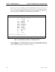
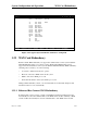
Figure 3-65. Typical WAN Port Redundancy Switch in CPU RCON System
3.22.2 Cross-Connect WAN Card Redundancy Switching
In cross-connect systems, WAN redundancy requires a WAN-R DUAL card in slot W4 (as
marked on its faceplate ejector). This card becomes a redundant card for the WAN cards in
slots W1 through W3 if it is equipped with matching DSX/CEPT, CSU, or HDSL modules,
and if those modules are installed in the same positions on both WAN cards. This protection
scheme is known as 1-in-N redundancy. When a switch occurs, a relay on the WAN-R card
switches the output of that card to the corresponding pins on the WAN connector of the
Interface card.
The following restrictions apply to cross-connect WAN redundancy:
You must install the WAN-R card in slot W4 for redundancy.
If you install it in slot W1,
W2 or W3, it will work only as a standard WAN card with two ports.
If the plug-in modules on the WAN-R card do not match those on a card in slot W1, W2,
or W3, the WAN-R card will not behave as a backup for that active WAN card.
The
system will not reject the card, but it will not switch even if the active WAN card fails.
If a standard WAN card is in slot W4, the system does not support WAN redundancy.
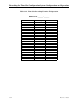
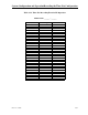
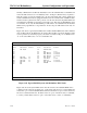
Node_1 | | 12-31-99 14:33
Slot Installed Status Slot Installed Status
C1 CPU RCON IF INTF+modem
C2 U1 ALR ssss
P1 U2 E&M 4Wx8-6 ssssssss
P2 U3 FXS 2Wx8-9 ssssssss
P3 U4 FXO 2Wx8-9 ssssssss
W1 DSX+DSX rr U5 HSU 366x2 ss
W2 CEPT+CEPT aa U6 OCU-DPx5 sssss
W3 CSU+CSU as U7 FRAD-10 ssssssss
W4 DSX+DSX aa U8 SRU 232x10 ssssssssss
F1 PS1 R1 RINGER
F2 PS2
Alarms | Config | Del | accepT | Xcon | sYs | Logout | Oos | cpusWtch