
Specifications


Reference Guide 5-13
Interface Card Interface Card User Screens and Settings
A network clock is the best Primary Clock source. To select this source, set the Primary Clock
field to
wan
, and then specify the WAN link to which the clock source is connected (for
example,
w1-1
for T1 or E1 link 1 on the WAN card in chassis slot W1). The WAN clock
source will be either 1.544 or 2.048 Mbps (T1 or E1 link). This clock must be accurate to
within ±50 parts per million (50 x 10
-6
).
Select
int
to have the system generate a clock from its own internal crystal oscillator. The
stability of this Stratum 4 clock is ±25 parts per million (25 x 10
-6
). If you use the system’s
internal crystal oscillator as a clock source, all other devices attached to the network should
also derive their timing from it.
Select
serv
to use a primary clock derived from an ADPCM server card in the system. If yo
uchoose this seeting, also specify the associated card slot (
P1, P2, or P3
). If you select a slot
that contains any other type of server card, the message CARD CANNOT BE SELECTED
appears.
Select
user
for a primary clock from a BRI card in the system. If you select
user
, also specify
the chassis slot location of the desired card (
U1 to U8
), followed by the card prot from which
the clock will be provided (
u1-1 through u8-8
) as required. If you select a chassis slot that
contains any other type of user card, the message CARD CANNOT BE SELECTED appears.
SECONDARY CLOCK
If the Primary Clock signal fails, the system automatically switches to an operator-defined
Secondary Clock source. The secondary clock source may be a different WAN link, server,
user card, or external source, or it can be the system’s internal crystal oscillator. Although a
secondary clock source is not required for system operation, you should always provide one
for the system.
CURRENT CLK
The Current Clock field shows the primary or secondary clock now in operation. You cannot
edit this field.
Note:
Jumper positions will affect the available choices.
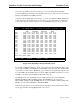
5.5.2 Signaling Conversion Table Screen
Signaling conversion is required when cross-connecting a T1 (ANSI) voice circuit to E1
(ITU-T). This process translates the sequences of the ABCD signaling bits to allow proper
signaling between the two carrier types.