
Specifications


2-4 Reference Guide
Model No.
Running Head
Introduction System Installation
2.1.4.2 Wall-Mount Installation Tips
To mount the chassis on a wall, first obtain a piece of standard, marine-grade plywood (3/8
inch diameter, typical) and bolt it firmly to the desired mounting surface. This board must be
long and wide enough to cover the entire chassis length and height. The surface must be able
to support the total weight of the system (chassis plus plug-in cards).
2.1.4.3 Tabletop Installation Tips
The chassis should be placed on a flat, smooth surface (e.g., a table) that is free of
contaminants. This surface should be capable of supporting a fully equipped chassis. Be sure
to allow enough clearance above and below the chassis for proper air circulation. You must
use the metal brackets and feet furnished with the chassis for this purpose.
2.1.5 Installing the Chassis
2.1.5.1 Front-Loading Chassis with Power Supplies on Side
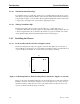
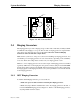
The front-loading chassis with power supplies on the side has eight holes on each side, as
shown in Figure 2-1. These holes are for mounting in a standard 19-inch or 23-inch rack (48.2
or 58.4 cm). The holes labeled “T” on the bottom are for tabletop mounting.
Figure 2-1. Mounting Holes for Front-Loading Chassis with Power Supplies on the Side
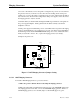
Figure 2-2 shows the mounting bracket holes. To mount the chassis in a rack, first attach the
brackets to the sides of the chassis, using the four associated 10-32 x 1/4” screws. You can
attach the brackets to either the front or rear of the chassis. Then, use the four 12-24 x 1/4”
screws to mount the bracketed chassis on the rack.
T
o
p
B
o
t
t
o
m
B
a
c
k
F
r
o
n
t
t
t