S1825 - S1833 - S1847 Installation & Service Manual 2 WARTUNGS & INSTALLATIONS HANDBUCH 2 5 MANUAL DE SERVICIO & MANUAL DE INSTALACIÓN 18 3 MANUEL D’ENTRETIEN & MANUEL D’INSTALLATION 34 4 INSTALLATION & SERVICE MANUAL 50 1 ONDERHOUDS & INSTALLATIEHANDLEIDING 66 : INSTRUKCJA MONTAŻU I SERWISU 82
WICHTIGER HINWEIS Dieses Wartungshandbuch ist für die Verwendung durch Personen vorgesehen, die über ausreichend Hintergrundwissen im Bereich Elektrik, Elektronik, Kältetechnik und Maschinen verfügen. Jeder Versuch, das Gerät zu installieren oder zu reparieren, kann zu Personenschäden oder Beschädigungen des Geräts führen.
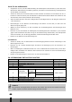
INHALT SICHERHEITSMASSNAHMEN 4 INSTALLATION VON GERÄTEN FÜR DEN INNENUND AUSSENBEREICH 5 ELEKTRISCHER ANSCHLUSS 12 LUFTSPÜLUNG 14 G TESTBETRIEB 16 WARNUNG! Installieren oder entfernen Sie das Gerät nicht selbst bzw. schließen Sie es nicht selbst erneut an. • Eine falsche Installation kann zu einem Wasseraustritt, Stromschlag, Kühlmittelaustritt oder zu einem Brand führen. Bitte wenden Sie sich für die Installationsarbeiten an einen autorisierten Händler oder einen spezialisierten Kühltechniker.
SICHERHEITSMASSNAHMEN Folgende Punkte sollten aus Sicherheitsgründen immer eingehalten werden: • Lesen Sie die folgende WARNUNG vor der Installation der Klimaanlage. • Befolgen Sie die hier aufgeführten Vorsichtsmaßnahmen, da sie wichtige Punkte in Bezug auf Ihre Sicherheit enthalten. • Heben Sie diese Anweisungen nach dem Lesen zusammen mit dem Benutzerhandbuch an einem sicheren Ort auf, um später darin Informationen nachschlagen zu können.
G VORSICHTSMASSNAHMEN Installieren Sie das Gerät nicht an Orten, an denen brennbare Gase entweichen. • Wenn Gas austritt und sich um das Gerät ansammelt, kann es zu einer Explosion kommen. Führen Sie die Entlüftungs- bzw. Rohrarbeiten gemäß den Installationsanweisungen durch. • Wenn die Entlüftungs- bzw. Rohrarbeiten falsch ausgeführt werden, kann Wasser aus dem Gerät austreten und Gegenstände im Haushalt nass machen und beschädigen.
Gerät für den Außenbereich • Vergewissern Sie sich, dass die Wärmestrahlung des Verdampfers nicht behindert ist, wenn über dem Gerät für den Außenbereich eine Markise gebaut ist, um direkte Sonneneinstrahlung oder Regenwasser auf dem Gerät zu vermeiden. • Achten Sie darauf, dass hinter dem Gerät und links daneben ein Abstand von mindestens 30 cm vorhanden ist. Achten Sie darauf, dass der Abstand vor dem Gerät mindestens 200 cm und daneben an der Anschlussseite (rechte Seite) mindestens 60 cm beträgt.
3 2 Mindestens 15 cm. 1 Min des ten s 12 cm. Mindeste ns 12 cm . Luf tfilt er LIN des KS M ten i s 30 ncm. A Luftauslass Nach oben mindestens 60 cm. 6 s ten des Min TEN 0 cm. IN H 3 Fernsteuerung 7 Blechschraube B ST 2,9 x 10-C-H 9 8 s nB este ind E M cm. N R VO 200 Bilden Sie mit dem Anschlusskabel eine Schleife. Halterung für Fernsteuerung C Min RECH des ten TS s 60 cm.
1. Anbringen der Installationsplatte 1. Befestigen Sie die Installationsplatte a horizontal an Konstruktionselementen der Wand und achten Sie darauf, dass um die Installationsplatte ein Abstand vorhanden ist. 2. Bohren Sie bei Ziegelwänden, Betonwänden usw. acht h Löcher mit einem Durchmesser von 5 mm in die Wand. Setzen Sie die Klemmbefestigungen b für die geeigneten Schrauben c ein. G 3. Befestigen Sie die Installationsplatte a mithilfe von acht h Schrauben des Typs A c an der Wand.
2. Bohren Sie ein Loch in die Wand. 1. Bestimmen Sie anhand der Zeichnung in Abbildung 5 die Lochpositionen und bohren Sie ein a Loch 65 mm tief in die Wand, wobei das gebohrte Loch leicht zur Außenseite hin schräg verläuft. Dadurch wird verhindert, dass Wasser in den Innenbereich gelangt. 2. Verwenden Sie immer ein Kabelschutzrohr, wenn Sie in ein Metallgitter, eine Metallplatte usw. bohren. 3. Installation des Verbindungsrohrs und des Ablaufs 1. Verlegen Sie den Ablauf immer nach unten.
Oberer Haken Unterer Haken Polstermaterial Abb. 9 4. Installation des Geräts für den Innenbereich 1. Führen Sie die Rohre durch das Loch in der Wand. 2. Bringen Sie die obere Klammer auf der Rückseite des Geräts für den Innenbereich auf dem oberen Haken der Installationsplatte an und bewegen Sie das Gerät seitwärts, um zu überprüfen, ob es sicher eingehängt ist. 3.
INSTALLATION DES GERÄTS FÜR DEN AUSSENBEREICH Sicherheitsmaßnahmen für die Installation des Geräts für den Außenbereich • Installieren Sie das Gerät für den Außenbereich auf einem starren Untergrund, um übermäßige Betriebsgeräusche und Vibrationen zu verhindern. • Bestimmen Sie den Bereich für die Luftauslassöffnungen, an dem die abgegebene Luft nicht blockiert wird. • Falls der Ort der Installation starken Winden ausgesetzt ist (z. B.
festzudrehen. Verbinden Sie das Verbindungsstück für das Entleeren mit dem Ablaufschlauch (nicht im Lieferumfang enthalten). Damit kann Kondenswasser, das während des Heizmodus der Klimaanlage erzeugt wird, abgelassen werden. Verbindungss Dichtring tück für das Entleeren Öffnung an der Unterseite des Geräts für den Außenbereich Dichtring Ablaufrohr Abb. 13 ANSCHLUSS DES KÜHLMITTELROHRS • Richten Sie die Mitte der Rohre zueinander aus.
2. Die zugeführte Spannung sollte im Bereich von 95 bis ca. 105 % der Nennspannung in einer Tabelle mit der Nennspannung liegen. 3. Im Stromkreis sollten ein Kriechstromschutz und ein Hauptschalter mit einer 1,5-fachen Leistung des Maximalstroms des Geräts installiert sein. 4. Achten Sie darauf, dass die Klimaanlage gut geerdet ist. 5. Schließen Sie die elektrischen Leitungen gemäß dem Stromlaufplan an, der sich auf dem Schild des Geräts für den Außenbereich befindet. 6.
Schließen Sie das Kabel am Gerät für den Außenbereich an (siehe Abb. 21) 1. Entfernen Sie die elektrischen Bauteile vom Gerät für den Außenbereich. 2. Schließen Sie die Verbindungskabel an die Anschlüsse auf dem Anschlussblock der Geräte für den Innen- und Außenbereich an, die über die entsprechenden Nummern verfügen. 3. Bilden Sie eine Schlaufe der Verbindungskabel der Geräte für den Innen- und Außenbereich wie in der Zeichnung gezeigt, um das Eindringen von Wasser zu verhindern. 4.
• Feuchtigkeit im Kühlmittelkreislauf kann gefrieren und die Kapillarleitungen verstopfen. • Wasser kann zu Korrosion von Bauteilen im Kühlsystem führen. • Beschädigungen des Verdichters. Daher muss die Rohrverbindung zwischen dem Gerät für den Innen- und Außenbereich immer getestet und mithilfe einer Vakuumpumpe entleert werden, um nicht kondensierbare Gase und Feuchtigkeit aus dem System zu entfernen.
Prüfpunkt bei Gerät für Innenbereich D C B A Abdeckung D Prüfpunkt bei Gerät für Außenbereich Abb. 25 TESTBETRIEB Führen Sie einen Testbetrieb durch, nachdem Sie die Prüfung der elektrischen Streuung und die Gasleckprüfung abgeschlossen haben. Die Dauer des Testbetriebs sollte länger als 30 Minuten sein. 1. Öffnen Sie die Abdeckung und heben Sie diese auf einen Winkel an, bis sie fest bleibt. Heben Sie die Abdeckung nicht weiter an, wenn sie bei einem hörbaren Klicken stoppt. 2.
2 17
AVISO IMPORTANTE: Este manual de servicio técnico está dirigido a personas con suficientes conocimientos de electricidad, electrónica, refrigeración y mecánica. Cualquier intento de instalar o reparar el aparato puede provocar lesiones y daños materiales. Ni el fabricante ni el vendedor se hacen responsables de la interpretación de esta información ni asumen ninguna responsabilidad en relación con su utilización.
ÍNDICE PRECAUCIONES DE SEGURIDAD 20 INSTALACIÓN DE LOS MÓDULOS INTERIOR Y EXTERIOR 21 CONEXIONES ELÉCTRICAS 28 PURGA DE AIRE 30 PRUEBAS DE FUNCIONAMIENTO 32 G ¡AVISO! No instale, desinstale ni reinstale el aparato por sí mismo. • Una instalación incorrecta puede motivar fugas de agua, descargas eléctricas, pérdidas de refrigerante o incendios. Le rogamos que se ponga en contacto con un distribuidor autorizado o un técnico instalador de aire acondicionado para realizar la instalación.
PRECAUCIONES DE SEGURIDAD Deberán observarse siempre las siguientes precauciones de seguridad: • Lea las siguientes ADVERTENCIAS antes de instalar el acondicionador de aire. • Siga las precauciones que se ofrecen aquí, ya que incluyen aspectos importantes relacionados con su seguridad. • Después de leer estas instrucciones, guárdelas junto con el manual del usuario en un lugar donde estén a mano para futuras consultas.
G PRECAUCIONES No instale el aparato en un lugar donde existan escapes de gas inflamable. • Si existe un escape de gas y éste se acumula en la zona próxima al aparato, puede originarse una explosión. Instale los conductos y el desagüe de acuerdo con las instrucciones de instalación. • Si los conductos o el desagüe presentan algún defecto, pueden producirse fugas de agua y causar daños en el mobiliario de su hogar.
Módulo exterior • Si se construye un toldo sobre el módulo exterior para protegerlo de la luz solar directa o de la lluvia, compruebe que no obstaculice la radiación térmica del condensador. • Asegúrese de que el espacio libre en la parte trasera del módulo y en el lateral izquierdo sea de 30 cm como mínimo. El espacio libre delante del aparato debe ser de 200 cm como mínimo, y en el lateral de conexión (lateral derecho), un mínimo de 60 cm.
3 2 15 cm o más 12 c m 1 om ás 12 cm o más Filt ro d e air e A IZQ 30 UIERD cm o m A Salida de aire ás ENCIMA 60 cm 6 RÁS DET o más cm 30 Mando a distancia 7 Tornillo de montaje B ST2,9 x 10-C-H 9 8 B TE s AN DEL o má cm 0 0 2 G G Haga un bucle con el cable de conexión C Soporte del mando a distancia DE 60 RECH cm A om ás PRECAUCIÓN • Asegúrese de que el aparato disponga de un espacio libre a ambos lados de más de 12 cm.
1. Coloque la placa de instalación 1. Coloque la placa de instalación a en horizontal sobre componentes que formen parte de la estructura de la pared con espacio suficiente alrededor. 2. Si la pared es de ladrillo, hormigón o materiales similares, practique ocho h orificios de 5 mm de diámetro con un taladro. Introduzca los ganchos de anclaje b apropiados para los tornillos de montaje c. G 3. Fije la placa de instalación a a la pared mediante ocho h tornillos de tipo A c.
2. Practique un orificio en la pared 1. Determine la posición del orificio de acuerdo con el diagrama indicado en la fig. 5. Practique un a orificio de 65 mm en dirección ligeramente descendente hacia el exterior, con el fin de evitar que el agua penetre en el interior. 2. Cuando practique orificios en rejillas o chapas metálicas y otros materiales similares, utilice siempre prensaestopas. 3. Instalación de los conductos de conexión y desagüe 1.
Gancho superior Gancho inferior Almohadilla Fig. 9 4. Instalación del módulo interior 1. Pase el conducto a través del orificio de la pared. 2. Enganche la garra superior de la parte posterior del módulo interior en el gancho superior de la placa de instalación; después, mueva el módulo interior de lado a lado para comprobar que esté bien sujeto. 3. La conexión de los conductos puede realizarse con facilidad levantando el módulo interior colocando una almohadilla entre el módulo y la pared.
INSTALACIÓN DEL MÓDULO EXTERIOR Precauciones para la instalación del módulo exterior • Instale el módulo exterior sobre una base rígida para evitar incrementar el nivel de ruido y vibraciones. • Oriente la salida del aire hacia una dirección que esté libre de obstáculos.
Junta Unión de desagüe Orificio de la base del módulo exterior Junta Conducto de desagüe Fig. 13 CONEXIÓN DEL CONDUCTO DE REFRIGERANTE • Alinee el centro de los conductos. • Apriete lo suficiente la tuerca abocardada con los dedos y, después, apriétela con una llave de tuercas dinamométrica, como se indica (ver figs. 18 y 19). • Elija el par de apriete correcto (indicado en la tabla 1) para evitar dañar los conductos, las piezas de conexión y las tuercas.
5. Realice las conexiones de acuerdo con el esquema de conexión eléctrica adherido al panel del módulo exterior. 6. Todas las conexiones deben cumplir con la normativa y los reglamentos locales y nacionales en materia eléctrica, y deben ser realizadas por un electricista cualificado. 7. Debe utilizarse un circuito independiente y un enchufe exclusivo para el equipo de aire acondicionado.
4. Aísle los cables no utilizados (conductores) con cinta de PVC. Asegúrese de que no estén en contacto con ningún componente eléctrico ni metálico. One-twin Wiring Diagram Tapa Tornillo Outdoor unit 10mm 40mm Outdoor power supply 220-240V-50HZ Indoor unit G Indoor power supply 220-240V-50HZ Fig.
LONGITUD DEL CONDUCTO Y CANTIDAD DE REFRIGERANTE Longitud del conducto de Método de purga de aire conexión • • Cantidad de refrigerante adicional a la indicada en la etiqueta que hay que cargar Menos de 5 m Utilice una bomba de vacío. ------------------------ De 5 a 10 m Utilice una bomba de vacío. Diámetro del conducto para líquido: ø 6,35 (Longitud del conducto -5) x 30g Cuando traslade el aparato a otro lugar, realice la extracción mediante una bomba de vacío.
PRUEBAS DE FUNCIONAMIENTO Realice las pruebas de funcionamiento después de completar las comprobaciones de seguridad eléctrica y de fugas de gas. Las pruebas de funcionamiento deben durar más de 30 minutos. 1. Abra el panel y levántelo hasta un ángulo en el que se mantenga fijo. No levante el panel más allá de que se detenga produciendo un chasquido. 2.
5 33
NOTICE IMPORTANTE: Ce manuel d’entretien s’adresse à toute personne qui bénéficie de connaissances approfondies et d’une expérience solide en électricité, électronique, mécanique et techniques du froid. Tenter d’installer ou de réparer soi-même l’appareil est dangereux et peut entraîner des blessures ou endommager le matériel.
TABLE DES MATIERES CONSIGNES DE SECURITE 36 INSTALLATION DES UNITES INTERIEURE ET EXTERIEURE 37 INSTALLATION ELECTRIQUE 44 PURGE D’AIR 46 TEST DE FONCTIONNEMENT 48 G AVERTISSEMENT! Ne pas installer, ôter et/ou réinstaller l’unité soi-même. • Une installation incorrecte de l’équipement peut entraîner des fuites d’eau ou de fluide frigorigène, des décharges électriques, voire provoquer un incendie.
CONSIGNES DE SECURITE Les consignes de sécurité suivantes seront observées en toutes circonstances : • Lire attentivement l’AVERTISSEMENT ci-dessous avant d’installer le climatiseur. • Respecter les mises en garde énoncées dans ce manuel. Elles contiennent d’importantes informations de sécurité. • Après avoir lu ces instructions, veiller à les conserver avec le manuel utilisateur dans un endroit où il sera facile de les retrouver pour une consultation ultérieure.
G MISES EN GARDE Ne pas installer l’unité à proximité de fuites de gaz inflammables. • Le gaz qui s’échappe risque de s’accumuler autour de l’unité et de provoquer une explosion. Installer les éléments de drainage et de pompage conformément aux instructions d’installation. • Toute erreur d’installation des éléments de drainage et de pompage peut provoquer des fuites d’eau de l’unité et endommager les équipements ménagers.
Unité extérieure • Si l’on protège l’unité extérieure des rayons solaires ou de la pluie à l’aide d’un auvent, s’assurer que la chaleur du condenseur peut s’échapper librement. • Prévoir un dégagement supérieur à 30 cm à l’arrière et du côté gauche de l’unité, à 200 cm à l’avant et à 60 cm côté connexion (côté droit). • Ne pas placer d’animaux ni de plantes devant l’arrivée ou la sortie d’air, ni obstruer le passage d’aucune autre manière.
3 2 15 cm ou plus 15 c m 1 ou plu s 15 cm ou plus Filt re d ’air GA UCH E3 0 ou plu cm s Sortie d’air 60 cm au-dessus 6 A 0 cm E3 IÈR s ARR ou plu Télécommande 7 Vis de montage B ST 2,9 x 10-C-H 9 8 B cm 200 NT s AVA ou plu G G Enrouler le câble de connexion C Support de télécommande DRO ITE ou 60 cm plu s MISE EN GARDE • S’assurer que l’espace à gauche et à droite de l’unité intérieure est supérieur à 12cm.
1. Fixation du support de montage 1. Fixer le support de montage a horizontalement sur les structures du mur en prévoyant de l’espace tout autour. 2. Si le mur est en briques, en béton ou en matériau similaire, percer huit h trous de 5 mm de diamètre. Introduire le clip d’ancrage b afin de garantir un montage correct des vis c. G 3. Fixer le support de montage a au mur à l’aide de huit h vis de type « A » c.
2. Percer un trou dans le mur 1. Déterminer la position des trous en fonction du diagramme illustré à la Fig.5. Percer un a trou ( 65 mm) en inclinant légèrement vers le bas (côté extérieur) afin d’éviter la pénétration d’eau vers l’intérieur. 2. Veiller à toujours utiliser un guide de perçage de mur lors du perçage de grille métallique, de panneau métallique, etc. 3. Tuyau de raccordement et installation de drainage 1. Le flexible de drainage doit toujours être installé en pente.
Crochet supérieur Crochet inférieur Coussinet Fig. 9 4. Installation unité intérieure 1. Faire passer le tuyau par l’ouverture pratiquée dans le mur. 2. Placer l’attache supérieure située à l’arrière de l’unité intérieure sur le crochet supérieur du support de montage et déplacer l’unité latéralement pour s’assurer qu’elle est bien fixée. 3. Pour raccorder les tuyaux, soulever l’unité intérieure à l’aide d’un coussinet placé entre l’unité et le mur.
INSTALLATION DE L’UNITE EXTERIEURE Précautions d’installation de l’unité extérieure • Installer l’unité extérieure sur une base rigide afin d’éviter que le bruit et les vibrations ne soient amplifiés. • • Déterminer le sens de l’évacuation de l’air de façon à ce que l’air soit évacué librement.
le joint de drainage à l’extension du flexible de drainage (non livrée) afin que l’eau condensée qui se dégage lorsque le climatiseur fonctionne en mode chauffage puisse s’évacuer. Garniture Joint de drainage Ouverture dans le capot inférieur de l’unité extérieure Garniture Flexible de drainage Fig. 13 RACCORDEMENT DU TUYAU FRIGORIFIQUE • Aligner le centre des tuyaux. • Serrer l’écrou évasé d’abord à la main puis à l’aide d’un tendeur et d’une clé dynamométrique comme illustré (voir fig. 18 et fig.
3. Une protection contre les fuites de courant et un interrupteur principal d’une capacité de 1,5 fois le courant maximum de l’unité doivent être prévus dans le circuit électrique. 4. S’assurer que le climatiseur est bien relié à la terre. 5. Raccorder les câbles conformément au diagramme de connexions électriques situé sur le capot de l’unité extérieure. 6. L’ensemble du câblage doit être conforme aux normes et aux réglementations électriques locales et nationales.
3. Afin d’éviter toute infiltration d’eau, faire une boucle dans le câble de raccordement comme illustré sur le diagramme d’installation des unités intérieure et extérieure. 4. Isoler les cordons non utilisés (fils) à l’aide de ruban en PVC. Veiller à ce qu’ils ne touchent aucun élément électrique ou métallique. One-twin Wiring Diagram Couvercle Vis 10mm Outdoor unit 40mm Outdoor power supply 220-240V-50HZ Indoor unit G Indoor power supply 220-240V-50HZ Fig.
LONGUEUR DE TUYAU ET QUANTITÉ DE FRIGORIGÈNE Longueur tuyau de raccordement Méthode de purge d’air Quantité supplémentaire par rapport à la quantité normale de frigorigène à charger (suivant l’ étiquette signalétique) Moins de 5 m Utiliser la pompe d’aspiration ------------------------ de 5 à 10 m Utiliser la pompe d’aspiration Diamètre tuyau côté frigorigène : ø 6,35 (Longueur tuyau -5) x 30g • Si l’unité doit être déplacée, il convient de la purger au préalable à l’aide de la pompe d’aspiration.
Effectuer le test de fonctionnement après avoir achevé les contrôles de sécurité électrique et de fuite de gaz. Le test de fonctionnement doit durer plus de 30 minutes. 1. Ouvrir le panneau et le soulever jusqu’à son point de fixation. Ne pas dépasser le niveau du déclic. 2. Appuyer deux fois sur le bouton de commande manuelle jusqu’à ce que le témoin lumineux de mise en service s’allume. L’unité fonctionne alors en mode Froid forcé. 3.
3 49
IMPORTANT NOTICE: This service manual is intended for use by individuals possessing adequate backgrounds of electrical, electronic, refrigerant and mechanical experience. Any attempt to install or repair the appliance may result in personal injury and property damage. The manufacturer or seller cannot be responsible for the interpretation of this information, nor can it assume any liability in connection with its use.
CONTENTS SAFETY PRECAUTIONS 52 INSTALLATION OF INDOOR AND OUTDOOR UNITS 53 ELECTRICAL WORK 60 AIR PURGING 62 TEST RUNNING 64 G WARNING! Do not install, remove and/or reinstall the unit by yourself. • Improper installation can cause water leakage, electrical shock, reffrigerant leakage or fire. Please consult authorized dealer or specialized air conditioner engineer for the installation work. Please note faults caused by improper installation is not covered by warranty.
SAFETY PRECAUTIONS The following should be always observed for safety: • Be sure to read the following WARNING before installing the airconditioner. • Be sure to observe the cautions specified here as they include important items related to safety. • After reading this instructions, be sure to keep it together with the owners manual in a handy place for future reference. The airconditioner contains a refrigerant and can be classified as pressurized equipment.
G CAUTIONS Do not install the unit in a place where a flammable gas leaks. • If gas leaks and accumulates in the area surrounding the unit, it could cause an explosion. Perform the drainage/piping work according to the installation instruction. • If there is a defect in the drainage/piping work, water could leak from the unit and household goods could get wet and be damaged. INSTALLATION OF INDOOR AND OUTDOOR UNITS Read completely, then follow step by step. More than 15 cm. More than 12 cm.
• Ensure that the clearance around the back of the unit is more than 30cm and left side is more than 30cm. The front of the unit should have more than 200cm of clearance and the connection side (right side) should have more than 60cm of clearance. • Do not place animals and plants or other obstacles in the path of the air inlet or outlet. • Take the air conditioner weight into account and select a place where noise and vibration will not be an issue.
3 2 15 cm or more 12 c m 1 or m ore 12 cm or more Air filte r A 30 c LEFT mo r mo re Air outlet 60 cm above 6 K BAC more r mo c 0 3 Remote Controller 7 Mounting screw B ST2.9x10-C-H 9 8 B NT e FRO r mor o cm 0 20 G G Loop the connective cable C Remote controller holder 60 RIGHT cm or m ore CAUTION • Ensure that the space around the left and right of the indoor unit is more than 12cm. The indoor unit should be installed allowing a minimum clearance of 15cm from the ceiling.
1. Fit the Installation Plate 1. Fit the installation plate a horizontally on structural parts of the wall with spaces around the installation plate. 2. If the wall is made of brick, concrete or the like, drill eight (8) 5mm diameter holes in the wall. Insert G Clip anchor b for appropriate mounting screws c. 3. Fit the installation plate a on the wall with eight (8) type “A” screws c.
2. Drill a hole in the wall 1. Determine hole positions according to the diagram detailed in Fig.5. drill one (1) hole ( 65mm) slanting slightly downwards to outdoor side, this will prevent water to come indoors. 2. Always use wall hole conduit when drilling metal grid, metal plate or the like. 3. Connective pipe and drainage installation 1. Always run the drain hose sloping downward all the way. Do not install the drain hose as illustrated below. Do not block water flow by a rise. 2.
Upper Hook Lower Hook Cushion material Fig. 9 4. Indoor unit installation 1. Pass the piping through the hole in the wall. 2. Put the upper claw at the back of the indoor unit on the upper hook of the installation plate, move the indoor unit from side to side to see that it is securely hooked. 3. Piping can easily be made by lifting the indoor unit with a cushioning material between the indoor unit and the wall. Get it out after finish piping. 4.
OUTDOOR UNIT INSTALLATION Outdoor installation precaution • Install the outdoor unit on a rigid base to prevent increasing noise level and vibration. • Determine the air outlet direction where the discharged air is not blocked. • In the case that the installation place is exposed to strong wind such as a seaside, make sure the fan operating properly by putting the unit lengthwise along the wall or using a dust or shield plates.
Seal Drain joint Base pan hole of outdoor unit Seal Drain pipe Fig. 13 REFRIGERANT PIPING CONNECTION • Align the centre of the pipes. • Sufficiently tighten the flare nut with fingers, and then tighten it with a spanner and torque wrench as shown (see fig. 18 and fig. 19). • Select the correct tightening torque (shown table 1) in order to prevent the pipes, connecting pieces and nuts from being damaged. G Indoor unit tubing Flare nut Pipings Fig. 18 Fig.
6. All wiring must comply with local and national electrical standards and codes and be installed by qualified and skilled electricians. 7. An individual branch circuit and single receptacle used only for this air conditioner must be available. See the following table for suggested wire sizes and fuse specifications: Model < 5.2 kW G ≥ 5.2 kW Input Rated Current Power Cord Size (Switch/Fuse) Power supply 25A 1.5mm2 25A 2.
One-twin Wiring Diagram Outdoor unit Cover Screw 10mm 40mm Outdoor power supply 220-240V-50HZ Indoor unit Indoor power supply 220-240V-50HZ G Fig. 21 Indoor power supply 220-240V-50HZ CAUTION After the confirmation of the above conditions, prepare the wiring as follows: • Never fail to have an individual power circuit specifically for the air conditioner. As for the method of wiring, be guided by the circuit diagram posted on the inside of control cover.
PIPE LENGTH AND REFRIGERANT AMOUNT Connective pipe lenght Air purging method Additional amount above rating label amount of refrigerant to be charged Less than 5m Use vacuum pump. ------------------------ 5~10m Use vacuum pump. Liquid side pipe diameter: ø 6.35 (Pipe length-5)x30g • When relocate the unit to another place, perform evacuation using vacuum pump. • Make sure the refrigerant added into the air conditioner is in liquid form in any case.
TEST RUNNING Perform test running after completing gas leak and electrical safety check. The test running time should last more than 30 minutes. 1. Open the panel and lift the panel up to an angle which remains fixed. Do not lift the panel any further when it stops with a click sound. 2. Press the manual control button twice until the operating indicator lights up, the unit will operate on Forced Cool mode. 3. Check if all the functions works well during test running.
4 65
BELANGRIJKE OPMERKING: Deze onderhoudshandleiding is bedoeld voor personen die beschikken over voldoende kennis en ervaring op het gebied van elektrische apparaten, elektronica, koeltechniek en mechanische inrichtingen. Pogingen om het apparaat te installeren of te repareren kunnen leiden tot lichamelijk letsel en materiële schade. De fabrikant of verkoper is niet verantwoordelijk voor de interpretatie van deze informatie, en is niet aansprakelijk voor een ondoelmatig gebruik van deze informatie.
INHOUD VEILIGHEIDSMAATREGELEN 68 INSTALLATIE VAN BINNEN- EN BUITENUNIT 69 ELEKTRISCHE INSTALLATIE 76 REINIGEN MET LUCHT 78 PROEFDRAAIEN 80 G WAARSCHUWING! Installeer, verwijder of herinstalleer de unit niet zelf. • Een ondeskundige installatie kan leiden tot waterlekkage, elektrische schokken, koelmiddellekkage of brand. Raadpleeg voor de installatie een geautoriseerde dealer of specialisten op het gebied van airconditioning.
VEILIGHEIDSMAATREGELEN Neem altijd het volgende in acht met betrekking tot de veiligheid: • Lees de volgende WAARSCHUWING alvorens de airconditioning te installeren. • Neem de hier genoemde waarschuwingen in acht, aangezien deze belangrijke informatie bevatten met betrekking tot veiligheid. • Bewaar deze instructies, na het lezen ervan, samen met de gebruikershandleiding op een geschikte plaats, zodat u deze documenten gemakkelijk kunt raadplegen.
G WAARSCHUWINGEN Installeer de unit niet op een plaats waar brandbaar gas lekt. . • Als gas weglekt en zich verzamelt in het gebied rondom de unit, kan dit leiden tot een ontploffing. Breng de afvoer-/pijpleidingen aan in overeenstemming met de installatie-instructie. • Bij een defect in de afvoer-/pijpleidingen kan water uit de unit weglekken en kan huisraad nat worden en beschadigd raken. INSTALLATIE VAN BINNEN- EN BUITENUNIT Lees de informatie volledig door en ga vervolgens stap voor stap te werk.
Outdoor unit • Indien er een afdak over de buitenunit wordt gebouwd om blootstelling aan direct zonlicht of regen te voorkomen, dient ervoor te worden gezorgd dat de • condensor niet geblokkeerd is. Zorg ervoor dat de ruimte rond de achterzijde en de linkerzijde van de unit meer dan 30 cm bedraagt. Aan de voorzijde van de unit moet de ruimte meer dan 200 cm bedragen, terwijl bij de aansluitzijde (rechterzijde) een ruimte van 60 cm moet worden aangehouden.
3 2 Ten minste 15 cm Ten min ste 12 1 cm Ten minste 12 cm Luc htfil ter A LIN min KS te n ste 30 cm Luchtuitlaat 60 cm boven 6 ten TER cm ACH te 30 s min Afstandsbediening 7 Bevestigingsschroef B ST 2,9 x 10-C-H 9 8 B ten m OR VO 200 c ste in m G G Plaats de verbindingskabel in een lus C Houder afstandsbediening REC min HTS t e ste 60 n cm WAARSCHUWING • Zorg ervoor dat de ruimte links en rechts van de binnenunit meer dan 12 cm bedraagt.
1. Installatieplaat aanbrengen 1. Breng de installatieplaat a horizontaal op structurele delen van de wand aan en houd een ruimte rond de installatieplaat aan. 2. Als de wand is gemaakt van baksteen, beton of een vergelijkbaar materiaal, dienen acht h gaten met een diameter van 5 mm in de wand te worden geboord. Breng de verankeringsklem b voor de desbetreffende bevestigingsschroeven c aan. G 3. Monteer de installatieplaat a op de wand met acht h schroeven van het type “A” c.
2. Boor een gat in de wand 1. Bepaal de positie van de gaten aan de hand van het schema in Fig. 5. Boor één a gat (65mm) enigszins schuin omlaag in de richting van de buitenzijde; dit voorkomt dat er water naar binnen dringt. 2. Maak altijd gebruik van een boorgeleider bij het boren in metalen roosters, metalen platen of vergelijkbare materialen. 3. Installatie van aansluitleiding en waterafvoer 1. Laat de afvoerslang altijd helemaal schuin naar beneden lopen.
Bovenste haak Onderste haak Opvulmateriaal Fig. 9 4. Installatie van binnenunit 1. Voer de leiding door het gat in de wand. 2. Breng de bovenste klem aan op de achterzijde van de binnenunit, op de bovenste haak van de installatieplaat, beweeg de binnenunit horizontaal om te controleren of deze stevig vastzit. 3. Het leidingwerk kan gemakkelijk worden aangebracht door de binnenunit op te tillen met een opvulmateriaal tussen de binnenunit en de wand.
INSTALLATIE VAN DE BUITENUNIT Voorzorgsmaatregelen bij buiteninstallatie • Plaats de buitenunit op een stevige ondergrond om ongewenste geluiden en trillingen zo veel mogelijk te beperken. • • Kies de richting van de luchtuitlaat zodanig, dat de afgevoerde lucht niet wordt belemmerd.
Sluit de afvoerverbinding aan met een verlenging van de afvoerslang (niet meegeleverd). Zo kan het condenswater, dat zich vormt in de verwarmingsstand van de airconditioning, worden afgevoerd. Afdichtring Afvoerverbinding Gat in bodem van buitenunit Afdichtring Afvoerpijp Fig. 13 AANSLUITEN VAN DE KOELMIDDELLEIDINGEN • Lijn het midden van de leidingen uit. • Draai de wartelmoer eerst met de hand vast en draai de moer vervolgens met een steeksleutel en een momentsleutel vast zoals getoond in Fig.
3. Het voedingscircuit moet worden voorzien van een kruipstroombeveiliging met een capaciteit van 1,5 maal de maximale stroomsterkte van de unit. 4. Zorg ervoor dat de airconditioning goed geaard is. 5. Sluit de kabels aan volgens het bijgevoegde elektrisch aansluitschema, dat zich op het paneel van de buitenunit bevindt. 6.
3. Om binnendringen van water te voorkomen, dient de verbindingskabel in een lus te worden aangebracht, zoals wordt getoond in het installatieschema voor de binnen- en buitenunit. 4. Isoleer ongebruikte snoeren (geleiders) met PVC-tape. Zorg dat deze geen elektrische of metalen delen aanraken. One-twin Wiring Diagram Afdekking Schroef 10mm Outdoor unit 40mm Outdoor power supply 220-240V-50HZ Indoor unit G Indoor power supply 220-240V-50HZ Fig.
• Water kan corrosie van onderdelen in het koelsysteem veroorzaken. • Beschadiging van de compressor. Daarom moeten de binnenunit en het leidingwerk tussen de binnen- en de buitenunit altijd worden getest op lekkages en worden leeggepompt met behulp van een vacuümpomp om eventueel aanwezige niet-condenseerbare stoffen en vocht uit het systeem te verwijderen.
Controlepunt binnenunit D C B A Afdekking D Controlepunt buitenunit Fig. 25 PROEFDRAAIEN Na afloop van de gaslektest en de controle op elektrische veiligheid moet het systeem worden proefgedraaid. 1. Til het paneel omhoog totdat het vergrendeld is. Til het paneel niet verder omhoog wanneer het een klikgeluid heeft gegeven. 2. Druk de knop voor handmatige bediening tweemaal in totdat de bedrijfsindicator gaat branden; de unit werkt nu in de modus Geforceerde koeling. 3.
1 81
WAŻNA UWAGA: Niniejsza instrukcja serwisu przeznaczona jest dla osób posiadających znajomość instalacji elektrycznych, elektroniki, chłodnictwa i mechaniki. Wszelkie próby montażu lub naprawy urządzenia mogą spowodować uszkodzenia ciała i szkody w mieniu. Producent bądź sprzedawca nie ponosi odpowiedzialności za interpretację niniejszych informacji, nie ponosi też odpowiedzialności wynikającej z ich wykorzystania.
SPIS TREŚCI ŚRODKI BEZPIECZEŃSTWA 84 MONTAŻ JEDNOSTKI WEWN TRZNEJ I ZEWN TRZNEJ 85 PRACE ELEKTRYCZNE 92 USUWANIE POWIETRZA 94 PRACA PRÓBNA 96 G OSTRZEŻENIE! Nie wolno samodzielnie montować, demontować i/lub ponownie montować klimatyzatora. • Nieprawidłowa instalacja może spowodować wyciek wody, porażenie prądem, wyciek czynnika chłodniczego lub pożar. W sprawie montażu należy skonsultować się z autoryzowanym dostawcą lub ze specjalistą monterem urządzeń klimatyzacyjnych.
ŚRODKI BEZPIECZEŃSTWA Ze względów bezpieczeństwa, należy zawsze przestrzegać następujących zaleceń: • Przed montażem klimatyzatora należy konieczne przeczytać poniższe OSTRZEŻENIE. • Należy przestrzegać przestróg podanych w niniejszej instrukcji, ponieważ zawierają one ważne informacje dotyczące bezpieczeństwa. • Po przeczytaniu niniejszej instrukcji, należy przechowywać ją wraz z instrukcją obsługi w łatwo dostępnym miejscu w celu skorzystania z nich w razie potrzeby w przyszłości.
G PRZESTROGI Nie instalować jednostki w miejscu, gdzie występują wycieki łatwopalnego gazu. • Wycieki gazu i jego gromadzenie się w pobliżu jednostki mogą spowodować wybuch. Montaż instalacji odwadniającej / rur prowadzić zgodnie z instrukcją montażu. • W przypadku wystąpienia usterki w instalacji ściekowej / rurach, może nastąpić wyciek wody z jednostki, co może spowodować zamoknięcie oraz zniszczenie yposażenia domu.
Jednostka zewnętrzna • Gdy nad jednostką zewnętrzną zbudowany jest daszek mający chronić ją przed bezpośrednim oświetleniem słonecznym lub przed deszczem należy dopilnować, aby nie utrudniało to odprowadzania ciepła ze skraplacza. • Należy dopilnować, aby odstęp z tyłu i z lewej strony jednostki wynosił ponad 30 cm. Z przodu jednostki • należy pozostawić ponad 200 cm odstęp, a od strony przyłączy (z prawej strony) – ponad 60 cm. • nowiły problemu.
3 2 15 cm lub więcej 12 c m 1 lub wię cej 12 cm lub więcej Filtr pow ietrz a LEW A 30 cm STRO N Wylot powietrza lub wię A cej A 60 cm lub więcej 6 TYŁ więcej lub cm 30 Pilot zdalnego sterowania 7 Wkręt mocujący B ST 2,9 × 10-C-H 9 8 B ÓD ej PRZ b więc lu cm 0 20 Zwinąć przewód łączący Uchwyt pilota zdalnego sterowania C PRAW A 60 cm STRO lub N wię A cej G PRZESTROGA G UWAGA • Należy pozostawić ponad 12 cm wolnego miejsca z lewej i z prawej strony jednostki wewnętrznej.
1. Mocowanie płyty montażowej 1. Przymocuj płytę montażową a w pozycji poziomej do konstrukcji nośnej ściany, z zachowaniem odstępów od płyty. 2. Jeśli ściana zbudowana jest z cegły, betonu lub podobnych materiałów, wywierć w ścianie osiem (8) G otworów o średnicy 5 mm. Załóż kołki rozporowe b, odpowiednie dla wkrętów montażowych c. 3. Zamocuj płytę montażową a na ścianie ośmioma (8) wkrętami typu „A” c.
2. Wiercenie otworu w ścianie 1. Ustal położenie otworu według schematu przedstawionego na rys. 5. Wywierć jeden (1) otwór (65 mm) pod kątem, lekko w dół, na zewnątrz budynku. Zapobiegnie to wlewaniu się wody do środka. 2. Wykonując otwór w metalowej kracie, płycie, itp. należy zawsze używać rury osłonowej. 3. Montaż rury łączącej i instalacji ściekowej 1. Przewód ściekowy należy zawsze prowadzić ze spadkiem na całej długości. Nie należy instalować przewodu ściekowego w sposób przedstawiony poniżej.
Hak górny Hak dolny Element amortyzujący Rys. 9 4. Montaż jednostki wewnętrznej 1. 2. Przełóż rurę przez otwór w ścianie. Górny zaczep z tyłu jednostki wewnętrznej nałóż na hak górny płyty montażowej, przesuń jednostkę wewnętrzną w obie strony na boki, aby sprawdzić, czy jest pewnie zawieszona. 3. Podłączenie rur można łatwo wykonać, wkładając element amortyzujący pomiędzy jednostkę wewnętrzną a ścianę. Wyjmij go po podłączeniu instalacji rurowej. 4. Dosuń dolną część klimatyzatora do ściany.
MONTAŻ JEDNOSTKI ZEWNęTRZNEJ Środki ostrożności związane z montażem jednostki zewnętrznej • Aby uniknąć wzrostu poziomu hałasu i drgań, jednostkę zewnętrzną należy zamontować na sztywnej pod- • • Ustalić kierunek wylotu powietrza tak, aby nie tamować wypływu powietrza. • ekranu. stawie. W przypadku miejsca montażu wystawionego na silny wiatr, jak np.
przewód ściekowy (nie wchodzi w skład dostawy). W ten sposób można odprowadzić skroploną wodę powstającą podczas pracy klimatyzatora w trybie grzania. Uszczelka Złącze instalacji ściekowej Otwór w wanience ściekowej jednostki zewnętrznej Uszczelka Przewód ściekowy Rys. 13 PODłąCZANIE PRZEWODóW CZYNNIKA CHłODZąCEGO • Ustaw środki rur w jednej osi.
3. W obwodzie zasilania należy zainstalować zabezpieczenie przeciwwypływowe (ziemnozwarciowe) oraz wyłącznik zasilania o obciążalności 1,5-krotnie większej od maksymalnego prądu jednostki. 4. Zapewnić, aby klimatyzator był dobrze uziemiony. 5. Podłącz przewody elektryczne zgodnie z dołączonym schematem połączeń znajdującym się na panelu jednostki zewnętrznej. 6.
3. Aby zapobiec przedostawaniu się wody, należy uformować pętlę na przewodzie łączącym, jak pokazano na schemacie montażowym jednostki wewnętrznej i zewnętrznej. 4. Nieużywane przewody (żyły) zaizolować taśmą PCV. Upewnić się, że nie stykają się one z żadnymi elementami elektrycznymi ani metalowymi.
DłUGOść RURY I ILOść CZYNNIKA CHłODZąCEGO Długość rury łączącej Metoda usuwania powietrza Dodatkowa ilość czynnika chłodzącego, którą należy dodać ponad ilość podaną na tabliczce znamionowej Poniżej 5 m Użyj pompy próżniowej ------------------------ 5~10m Użyj pompy próżniowej Średnica rury po stronie ciekłej: Ø 6,35 (Długość rury-5) × 30 g • Po przeniesieniu jednostki w inne miejsce, do usuwania powietrza należy użyć pompy próżniowej.
PRACA PRóBNA Po sprawdzeniu szczelności instalacji i bezpieczeństwa instalacji elektrycznej należy wykonać uruchomienie próbne. Praca próbna powinna trwać dłużej niż 30 minut. 1. Otwórz panel i unieś go, ustawiając pod kątem, przy którym pozostanie w stałym położeniu. Jeżeli usłyszymy dźwięk kliknięcia i panel zatrzyma się, nie podnosić go dalej. 2. Naciśnij dwukrotnie przycisk sterowania ręcznego, aż zaświeci się kontrolka pracy, jednostka będzie pracowała w trybie wymuszonego chłodzenia. 3.
:
DISTRIBUTED IN EUROPE BY PVG INTERNATIONAL B.V. 2 DEUTSCHLAND PVG Deutschland GmbH Siemensstrasse 31 47533 KLEVE tel: 0800 - 9427646 fax: +31 (0)412 648 385 email: pvgdeutschland@zibro.com 6 DANMARK Appliance A/S Blovstroed Teglvaerksvej 3 DK-3450 ALLEROED tel: +45 70 205 701 fax: +45 70 208 701 email: appliance@appliance-group.com 5 ESPAÑA PVG España S.A. Pol. Ind.