
User's Manual


Zinwave 2700 DAS – User Manual
Issue 1.2
April 2007
© Zinwave Ltd. 2007
1.3.1 RF Signal Distribution
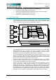
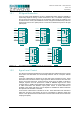
In the HU a RF signal distribution circuitry is implemented which gives the flexibility to
dynamically adjust the routing of radio transceivers to AU. In its default configuration
the HU routes each electrical I/O port to two adjacent optical ports. By enabling a set
of switches in the circuitry this distribution can be changed to simultaneously route two
electrical I/O ports to four optical ports or to route all four electrical I/O ports to all eight
optical ports.
Figure 1-3: Five different possibilities to distribute the input signals.
1.3.2 Signal Level Control
The Zinwave 2700 DAS implements a two-stage attenuator based approach to signal
level control. All attenuators are electronically switched and do not require manual
handling.
A first set of attenuators is situated in the HU right at the electrical I/O ports. These
attenuators are intended to balance signal power of different services such that each
service covers the same area. A high frequency signal, such as UMTS or WLAN for
example, requires more RF power than a PMR or GSM900 signal for the same
coverage area. In addition these attenuators allow the HU to be connected to a range
of radio transceivers with different output power values. A similar attenuator is
provided in the uplink path which can be adjusted to establish link balance between
the uplink and the downlink of the DAS.
A second set of attenuators is situated in the AU. These attenuators are intended to
adjust the cell size of the specific AU and to compensate for different optical loss
values. In the uplink direction the attenuator is used to trade-off cell size and minimum
coupling loss (MCL).
HU
I/O 1
I/O 2
I/O 3
I/O 4
HU
I/O 1
I/O 2
I/O 3
I/O 4
HU
I/O 1
I/O 2
I/O 3
I/O 4
HU
I/O 1
I/O 2
I/O 3
I/O 4
HU
I/O 1
I/O 2
I/O 3
I/O 4
4 × 1:2 2 × 1:2 / 1 × 2:4
1 × 2:4 / 2 × 1:2
2 × 2:4 1 × 4:8