Wireless LAN Device Series WLAN Outdoor Bridge ZW-2000-IA User Manual Version.
TABLE OF CONTENTS PREFACE.................................................................................................................................................................3 CH 1. ZW-2000 INSTALLATION ....................................................................................................................4 PACKING LIST .......................................................................................................................................................
VPN PASS-THROUGH .........................................................................................................................................66 U SING CLI M ENU ..............................................................................................................................................66 THE SYSTEM M ANAGEMENT ............................................................................................................................69 SNMP A GENT................................
Preface This guide is for the networking professional who installs and manages the Zinwell ZW-2000 outdoor product hereafter referred to as the “device”. To use this guide, you should have experience working with the TCP/IP configuration and be familiar with the concepts and terminology of wireless local area networks.
Ch 1. ZW-2000 Installation Packing List Before you start to install the ODU, make sure the package contains the following items: ● Wireless Outdoor Bridge unit * 1 ● Mounting Kit * 1 ● Waterproof (IP67) RJ-45 Cable (30M) * 1 ● Waterproof (IP66) RF Cable (1M) * 1 ● Power Over Ethernet Kit * 1 ● Ground Wire * 1 ● 2.5” /4” U bolts * 2 and Anchor * 4 ● RJ-45 Cable (1.
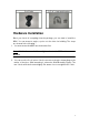
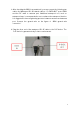
Hardware Installation Once you check off everything from the package, you can start to install the ODU. You can mount to a pipe, a pole or to the side of a building. The steps are showed in the following: 1. You must mount the ODU into the bracket first. Note: ALL the 4 screws had been tightened onto the ODU and Bracket 2. You can use the 2 or 4 inches U bolt to mount on the pipe, depending on the radius of the pipe.
3. After checking the ODU is mounted well, you can connect the following two cables: the Waterproof RJ-45 network cable to “ P+ DATA OUT” port of ODU and the RF cable to antenna port. Additional waterproof tool, such as waterproof tape, is recommended to use to enhance the waterproof function. It is suggested to have a lightening protector between antenna and antenna port. Connect the ground wire as the figure of “ ODU ground wire connection.” 4.
Caution: DON’T plug the power cord into PoE device before you finish install the antenna and Ground wire to ensure the safety. If the RJ-45 cable’ s length is not long enough to connect to your network device for indoor parts installation, you can extend the cable length. However, make sure the maximum length of the RJ-45 cable is shorter than 100M (about 109 yards) for normal operation under IEEE 802.3 standards.
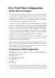
Ch 2. First Time Configuration Before Start to Configure There are two ways to configure the device, one is through web-browser, and the other is through Secure Shell CLI interface. To access the configuration interfaces, make sure you are using a computer connected to the same network as the device. The default IP address of the device is 192.168.2.254, and the subnet-mask is 255.255.255.0. The device has three operation modes (Router/Bridge/WISP).
types of operation mode. Router The wired Ethernet (WAN) port is used to connect with ADSL/Cable modem and the wireless NIC is used for your private WLAN. The NAT is existed between the 2 NIC and all the wireless clients share the same public IP address through the WAN port to ISP. The default IP configuration for WAN port is static IP. You can access the web server of device through the default WAN IP address 172.1.1.1 and modify the setting base on your ISP requirement.
also the wireless clients can survey and connect to the device. The following table shows the supporting combination of operation and wireless radio modes. Bridge Router WISP AP V V X WDS V V X Client V X V AP+WDS V V X Hereafter are some topologies of network application for your reference.
Examples of Configuration DEV 1 Internet LAN 192.168.2.254/24 WAN PPPoE connection Wireless Channel: 11 / SSID: ZPlus -G120-DEV 1 Broadband Modem MAC Address of WLAN(BSSID) 000000042728 DHCP Server enabled (IP Pool 192.168.2 .1~253) Router Mode With WDS + AP 192.168.2.x DEV 4 192.168.2.x LAN 192.168.3.1/24 WAN Dynamic IP address DEV 2 DHCP Server enabled ( IP pool 192.168.3 .2~254) LAN 1 9 2.168.2.
4. Press “Next>>” button then set the “Operation Mode” to “Router” mode. 5. Press “Next>>” button then disable “Time Zone” function. 6. Press “Next>>” button then set the IP address of LAN interface. 7. Press “Next>>” button then select the “PPPoE” for “WAN Access Type” and fill in the “User Name ” and “Password” fields.
8. Press “Next>>” button then select the “AP+WDS ” for “mode” and change the SSID to “DEV1”. 9. Press “Next>>” button then select “None ” for “Encryption” then press “Finished” button. 10. Wait for refreshing web page. 11. Use “WDS Settings” page to configure WDS.
Configure DEV2: 1. Access the web server (http://192.168.2.254) of device from the Ethernet port. Caution If you configure multiple devices in the same PC, since the devices have the same default IP address but different MAC addresses, it may cause you not able to access the web server of device. If the situation happens, please try to clean the ARP table of your PC by DOS command “arp –d” then you can access the web server of device using the default IP address. 2. Use Wizard page to setup device. 3.
5. Press “Next>>” button then set the IP address of LAN interface. 6. Press “Next>>” button then select the “AP+WDS ” for “mode” and change the SSID to “DEV2”. 7. Press “Next>>” button then select “None ” for “Encryption” then press “Finished” button. 8. Wait for refreshing web page.
9. Access the web server by new IP address “192.168.2.202” then use “LAN Interface” page to disable DHCP Server. 10. Wait for refreshing web page. 11. Use “WDS Settings” page to configure WDS.