Quick Start Installation Guide Zip HydroTap G5 Command Centre Chilled, Chilled/Sparkling models AFFIX PRODUCT LABEL HERE Australia UK Visit our website to download the manuals Quick Start Installation Guide 807120 v1.00 01.
Table of contents SECTION 1: Using the instructions.......................................................................3 SECTION 2: IMPORTANT SAFETY INSTRUCTIONS.............................................. 4 SECTION 3: WARNINGS AND REGULATORY INFORMATION............................. 6 SECTION 4: Technical data ................................................................................ 8 SECTION 5: Supplied parts checklist..................................................................
SECTION 1: Using these instructions Before you start ! This document is a Quick Start Installation Guide. For further details on installing and operating your HydroTap download & read the Command Centre installation and user instructions , which can be found online at: (Australia) www.zipwater.com (UK) specify.zipwater.co.uk Read and use the instructions supplied with individual kit components for a safe installation.
SECTION 2: IMPORTANT SAFETY INSTRUCTIONS ! Compliance In Australia electrical installation must comply with AS/ NZS3000. In Australia plumbing installation must comply with AS/NZS3500. In Australia For residential chilled models, all refrigeration must comply with AS/NZS 60335.2.24. In the UK the system must be installed in accordance with water supply byelaws, current IEE regulations and local authority byelaws.
SECTION 2: IMPORTANT SAFETY INSTRUCTIONS • • • • • • • Do not expose to temperatures exceeding 50˚C. Do not expose to naked flame or any incandescent material. Do not pierce or burn, even after use. Avoid shock. High concentration of gas may cause asphyxiation. Use only in an upright position. The cylinder must be used with the supplied pressure regulator.
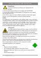
SECTION 3: WARNINGS & REGULATORY INFORMATION • ! The Zip HydroTap must be earthed, earthing is provided via the supplied power cord. The resistance of the earth connection to each exposed metal part must be less than 1Ω. Use the power cable supplied. It is the responsibility of the installer to ensure the power point is earthed. ! • All installation and service work must be completed by trained and suitably qualified tradespeople.
SECTION 3: WARNINGS & REGULATORY INFORMATION • Do not over tighten plumbing and hose connections. • Braided hoses supplied cannot be lengthened. • Be aware of the risks of hazards which could cause harm when handling compressed CO2. Assess the risks before starting the installation. • Do not proceed with a CO2 cylinder change if the seals are damaged. Take care not to cross thread the regulator, a cross threaded regulator poses a potential hazard.
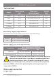
SECTION 4: Technical data Technical data # Model Power rating kW Dimensions W x D x H (mm) Weight (kg) CS100 0.37 330 (500)# x 477 x 333 36.5 C100 0.34 330 (500)# x 470 x 333 24.2 C40 0.16 330 x 470 x 333 24.2 CS Home 0.18 280 x 406 x 333 30 C Home 0.17 280 x 406 x 333 21 including vent tray Electricity supply requirements 220-240V 50Hz AC (for power requirement see table above).
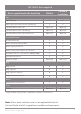
SECTION 5: Parts supplied Chilled Chilled & Sparkling HydroTap tap HydroTap pipes, tubes hoses and fittings Separate Mains mixer Tap Optional Optional Separate Mains mixer Tap fittings Optional Optional Separate Mains mixer Tap instructions Optional Optional Command Centre Mains electrical supply cable Water supply inlet hose Water supply inlet adaptor and strainer Ventilation kit (inc.
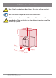
SECTION 6: Set up the ventilation ! Use of tools can be hazardous. Assess the risks before you start. Use instructions supplied with individual kit parts. 200mm ! A clearance envelope around all Command Centres must be provided to allow ventilation for the safe and effective use of the HydroTap system. 50mm Comm 50mm and Ce 10 Quick Start Installation Guide 807120 v1.00 01.
SECTION 6: Set up the ventilation CS100 & C100 models • Cold air is drawn in through the inlet vent and gap provided by the door buffers. • Warm air is exhausted through vent tray. • Inlet vent is mounted over cupboard side, door or floor cut-out (see below). • Observe 100mm inlet / outlet vent separation (see below). ! The vent tray must be fitted. It provides a safe exhaust for refrigerant gas in the unlikely event of a leak.
SECTION 6: Set up the ventilation C40 CS Home, C Home models • Cold air is drawn in through the inlet vent and lower gap provided by the door buffers. • Inlet vent is mounted over cupboard side, door or floor cut-out. • Warm air is exhausted through upper gap provided by the door buffers. Air outlet Inlet vent Air inlet 4mm door buffers (supplied) All models If cupboard temperature exceeds 35°C, additional ventilation is required.
SECTION 7: Fit the carbonation valve Chilled sparkling installations Avoid SPARKLING outlet Command Centre Carbonation valve flow adjustment • Use a 6mm Allen key or a large flat-blade screwdriver to adjust the valve. • Rotate the adjustment screw anti-clockwise to increase, + and clockwise to decrease the flow. • To measure the set flow rate, use a measuring jug or cup and run the sparkling water for 15 seconds. The HydroTap has a default 15 second dispense time, which will help in your flow rate setup.
SECTION 8: Connect the water supply ! Valves and fittings must be sealed with PTFE tape if compression seals are not included. Note Mixer tap installations also use a ‘Tee piece’ as part of the water supply plumbing connections, see the Tap installation instructions supplied with the Mixer Tap to connect the water supply if using the mixer tap option. Note correct strainer orientation.
SECTION 9: Install the CO2 cylinder and regulator Be aware of the risks of hazards which could cause harm when handling compressed CO2. Read the important safety instructions at the start of this instruction manual. Assess the risks before starting the installation. ! Secure the cylinder Ensure these is sufficient space to safely secure the cylinder and regulator.
SECTION 9: Install the CO2 cylinder and regulator CO2 regulator identification Universal G5 regulator II IIIII Braided hose connection IIII I I II III II IIIII I I I I III I I II III II II II II Outlet pressure I I I I III Cylinder pressure IIII Cylinder connection Regulator control knob 1.2kg cylinder non-adjustable regulator Regulator control knob Braided hose connection Cylinder connection 16 Quick Start Installation Guide 807120 v1.00 01.
SECTION 9: Install the CO2 cylinder and regulator Fit the regulator and connect the gas hose • • • • • • • Ensure all mating surfaces are clean. Turn the regulator OFF. Check the regulator and hose seals, inside the connectors. Connect the gas hose to the regulator. Carefully screw the regulator onto the cylinder connection. For the 1.2kg cylinder and Universal G5 regulator use the adaptor supplied. Connect the gas hose to the Command Centre (see section 10). Do not proceed if the seals are damaged.
SECTION 9: Install the CO2 cylinder and regulator Adjust the regulator II II IIIII I I I I III IIII I I II III II II I I II III IIIII Outlet pressure II II I I I I III Universal G5 regulator IIII Regulator control knob • Check the regulator is turned all the way OFF (anti-clockwise). • Turn the gas ON using the cylinder valve (2.64Kg cylinder), (anti-clockwise). • Turn the regulator control knob (clockwise +) to adjust the outlet pressure to 3.0 bar on the outlet pressure gauge.
SECTION 9: Install the CO2 cylinder and regulator Test for leaks Care must be taken when working with high pressure carbon dioxide, and in no case should the normal operating pressure of 3.0 bar be exceeded.
C res SECTION 10: Connect the Command Centre Generic installation instructions MAINS IN USB CHILLED OUTLET For HydroTap, mixer tap and any optional accessories, use instructions supplied with individual kit components. Mains power cable USB Tap CS75 res Braided hose HydroTap CO2 USB MAINS IN CHILLED OUTLET Do not connect to the mains socket until commissioning ! SPARKLING OUTLET Command Centre Connections key Installation diagrams are for illustrative purposes only.
C 175 comm SECTION 10: Connect the Command Centre CS100 models USB CHILLED The foam insulation supplied OUTLET must be fitted over the WHITE and BLUE pipes ! MAINS Mains IN Water BLUE WHITE check which way round still / sparkling CS 175 comm CO2 IN CHILLED SPARKLING OUTLET OUTLET MAINS IN CS Comm II II IIIII II II IIIII I I I I III Diagram for illustrative purposes only. II IIIII I I II III IIII II IIIII II II IIII Quick Start Installation Guide 807120 v1.00 01.
B res comm SECTION 10: Connect the Command Centre C40, C100 models MAINS IN MIXER OUT USB MIXER BOILING BYPASS VENT IN OUT IN The foam insulation supplied must be fitted over the BLUE pipe BYPASS OUT ! Mains Water BLUE C 175 comm USB CHILLED OUTLET C Comm MAINS IN check which way round still / sparkling CS 175 comm Diagram for illustrative purposes only. CO2 IN 22 CHILLED SPARKLING OUTLET OUTLET Quick Start Installation Guide 807120 v1.00 01.
C res SECTION 10: Connect the Command Centre CS Home models ! MAINS IN Mains Water USB CHILLED OUTLET The foam insulation supplied must be fitted over the WHITE and BLUE pipes BLUE WHITE CHILLED OUTLET SPARKLING OUTLET CS75 res USB MAINS IN CO2 IN CS Res II II IIIII II II IIIII I I I I III Diagram for illustrative purposes only. II IIIII I I II III IIII II IIIII II II IIII Quick Start Installation Guide 807120 v1.00 01.
BA res comm SECTION 10: Connect the Command Centre C Home models ! MAINS IN MIXER OUT Mains Water USB MIXER BOILING BYPASS VENT IN OUT IN BYPASS OUT The foam insulation supplied AMBIENT OUTLET must be fitted over the BLUE pipe BLUE C res USB MAINS IN CHILLED OUTLET C Res CS75 res Diagram for illustrative purposes only. USB MAINS IN 24 CHILLED OUTLET Quick Start Installation Guide 807120 v1.00 01.
SECTION 11: Commissioning ! ! 1 See User Guide 6 8 See page 13 Adjust carbonation valve Unpack, moisten o-rings & fit filter 2 Filter flush Connect electricity 3 Monitor display screen Flush 10 Litres through 4 7 TANK FLUSH 12:12 PM Follow the prompts to flush fresh water through the tank/s 3 times as shown by the cycle counter/s. The tank/s will fill automatically but when prompted use the tap to dispense and empty. Dispense water from the hot tank using the taps safety feature.
Notes 26 Quick Start Installation Guide 807120 v1.00 01.
Notes Quick Start Installation Guide 807120 v1.00 01.
Refer to User Guide for operation and maintenance. Zip Water (Australia) Pty Ltd ABN 46 000 578 727 67 - 77 Allingham Street, Condell Park NSW 2200 Postal: Locked Bag 80, Bankstown 1885 Australia Tel (+612) 9796 3100 Free call 1800 947 827 (1800 ZIP TAP) www.zipwater.com AU02691 WMKA21821 WMTS-105 Zip Water UK Trafalgar House, Rash’s Green, Dereham, Norfolk, NR19 1JG 0345 6 005 005 sales@zipindustries.co.uk specify.zipwater.co.uk 28 Quick Start Installation Guide 807120 v1.00 01.