Installation and Operating Instructions Zip Hydroboil ® Instant boiling water 10552 10551 11552 11551 12552 12551 04552 04551 Hydroboil 10 Litre White Hydroboil 10 Litre Stainless Steel Hydroboil 15 Litre White Hydroboil 15 Litre Stainless Steel Hydroboil 25 Litre White Hydroboil 25 Litre Stainless Steel Hydroboil 40 Litre White Hydroboil 40 Litre Stainless Steel 81447 - February 2004 HS010 HS110 HS015 HS115 HS025 HS125 HS040 HS140
Contents Read These Warnings First . . . . . . . . . . . . . .3 Installation Requirements . . . . . . . . . . . . . . .3 Installation Procedures . . . . . . . . . . . . . . . . .4 Step 1 – Positioning . . . . . . .4 Step 2 – Fastening . . . . . . . .4 Step 3 – Connecting . . . . . . .5 a) Plumbing . . . . . . . .5 b) Venting . . . . . . . . .5 c) Electrical . . . . . . . .6 Step 4 – Assembling . . . . . . .6 Step 5 – Commissioning . . . .6 Problem Solving . . . . . . . . . . . . . . . . . . . . . .
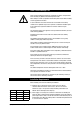
Read These Warnings First Please read all installation requirements, installation procedures and precautions before installing any Hydroboil instant boiling water heater. Never attempt to install any Hydroboil instant boiling water heater without reading all of the applicable instructions. In some hard water areas where mineral scale accumulation in the boiling chamber of the Hydroboil may become a problem, consideration should be given to the maintenance required.
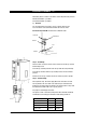
Installation Requirements continued This switch must provide all-pole disconnection and a contact seperation of at least 3 mm installed in accordance with wiring rules. c) Cold water supply with a minimum working pressure of 10 bar and a maximum working pressure of 7 bar connected via an isolation valve. d) Outlet drainage to a sink draining board or to a drip tray. e) Access to drainage from a vent situated at the base of the heater.
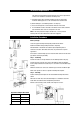
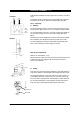
Installation Procedures Continued Install plumbing and wiring, and prepare pipe ends for connection as shown in step 3. Front View COLD INLET VENT OUTLET Screw heater chassis to wall using screws or bolts suited to the wall surface. Screws/bolts must be able to support the following weights when filled. Step 3 – Connecting a) Plumbing INLET POSITION For exposed plumbing connection, connect the cold water inlet pipe from the base of the heater directly to the 15 mm or 1/2 inch BSP compression fittings.
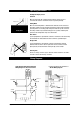
Installation Procedures continued Alternatively attach a tun dish to the wall as shown and plumb away to waste. Wall mounted tundish - p/n 99017 Sink mounted tundish- p/n 99018 c) Electrical For concealed electrical connection, connect a power cable from the rear of the heater to the terminal block within the heater as shown. Do not turn the power ON until the heater is filled with water.
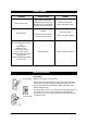
Problem Solving Symptom Possible Cause Solution Fails to dispense water. Water isolating valve turned off. Blocked filter, blocked meter tube, blocked strainer, jammed ball valve assembly, airlock in transfer tube. Check water supply valve. Contact a Zip authorised agent. No power. Water not boiling. Runs out of boiling water and fails to refill. Outlet tap drips. Overflow from vent. Excessive steam from vent. Power “on” but no heat. Overload repeatedly tripping with excessive steam.
Operating proceedures continued Reading the Display Screen Power On When the text 'Power On' is illuminated this indicates that the power is connected and turned on and that the heater is operating normally. Display Screen Boiling Water When the text 'Boiling Water' is illuminated this indicates that the contents of the boiling chamber has been brought to boiling point and is being maintained (normally within 1°C of boiling point).
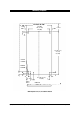
Mounting Template 374 (10L, 15L, 25L) 499 (40L) 295 (15L, 25L) 420 (40L) 120 CLEAR 39.5 150 CLEAR 39.5 20 TYP 591 (10L, 15L) 771 (25L) 831 (40L) EXTERNAL PLUMBING INTERNAL PLUMBING 54 41 TYP 28 41 41 COLD INLET VENT 42 145 188 (10L,15L, 25L) 313 (40L) BENCH TOP Wall template for 10, 15, 25 & 40 litre models.
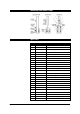
Connecting John Guest Fittings Spare Parts Page 10 of 12 Key Part Description 1 90096 Cistern Lid Clamp Kit 2 90097 Overload Kit 3 90120 Disc, Capsule, Lid, Gasket Kit 4 90490 Gasket Kit 5 90121 Cistern Lid Gasket Kit 6 90083 Float Valve Kit 7 90069 Jumper Valve kit 8 90496 O-ring Kit 9 90102 Cistern Float S/Nut Kit 10 90495 Banjo Screw Kit 11 90110 Fascia Light Kit 12 90501 Tap Top Kit 13 90499 Fascia Lens Kit 14 90494 Metering Tube Kit 2400 w 90527 Metering
17 4 16 4 3 2 19 1 9 4 5 18 6 8 14 10 7 8 20 4 17 8 11 21 13 15 12 Spare Parts Zip Hydroboil - Installation & Operating Instructions - 81447 - February 2004 Page 11 of 12
# Warranty Information The Zip appliance you have chosen is precision-built from the finest materials available and should give many years of trouble free service. Certain warranties may be implied by law into your contract with Zip. The warranty provided below is additional to these implied warranties and nothing set out below shall limit your statutory rights or rights at law.