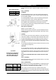
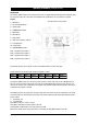
Installation and Operating Instructions ® Zip Hydroboil Plus Instant boiling water Stainless Steel model shown 203562 Zip Hydroboil Plus 3 Litre White 203561 Zip Hydroboil Plus 3 Litre Stainless Steel HP003 HP103 205562 Zip Hydroboil Plus 5 Litre White 205561 Zip Hydroboil Plus 5 Litre Stainless Steel HP005 HP105 207562 Zip Hydroboil Plus 7.5 Litre White 207561 Zip Hydroboil Plus 7.
Page 2 of 16 Zip Hydroboil Plus - Installation & Operating Instructions - 86584UK - February 2008
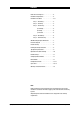
Contents Read these warnings first . . . . . . . . . . . . . . .4 Installation Requirements . . . . . . . . . . . . . . .4 Installation Procedures . . . . . . . . . . . . . . . . .5; 6 Step 1 – Positioning . . . . . . . . . . . . . . .5 Step 2 – Fastening . . . . . . . . . . . . . . . .5 Step 3 – Connecting . . . . . . . . . . . . . . .6 a) Plumbing . . . . . . . . . . . . . . . .6 b) Venting . . . . . . . . . . . . . . . . .6 c ) Electrical . . . . . . . . . . . . . . . .6 Step 4 – Assembling . . . . . .
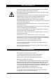
Read These Warnings First Please read all installation requirements, installation procedures and precautions before installing any Zip Hydroboil Plus instant boiling water heater. Never attempt to install any Zip Hydroboil Plus instant boiling water heater without reading all of the applicable instructions. In some hard water areas where mineral scale accumulation in the boiling chamber of the Zip Hydroboil Plus may become a problem, consideration should be given to the maintenance required.
Installation Requirements (continued) d) Outlet drainage to a sink draining board or to a drip tray. e) Access to drainage from a vent situated at the base of the heater. f) In all installation instances the walls of the heater must be vertical and the base horizontal, there can be no exceptions to this rule. Note: If the water pressure is likely to exceed 7 bar, a 3.5 bar pressure reducing valve must be installed in the cold water supply line.
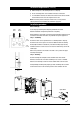
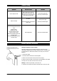
Installation Procedures (continued) Screws or bolts must be able to support the weight as shown in the chart on the left. Aprox weight when filled Step 3 – Connecting 3.0 Litre models 12.5 kg 5.0 Litre models 16.5 kg 7.5 Litre models 20.5 kg a) Plumbing For exposed plumbing connection, connect the cold water inlet pipe from the base of the heater directly to the 15 mm or half-inch compression fittings with the nuts and olives provided.
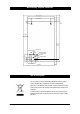
Wall Mounting Template Dimensions 274 (1.5 L & 3.O L) 38 (1.5 L & 3.O L) 304 (5.0 L & 7.5 L) 53 (5.0 L & 7.5 L) 19 150 CLEAR 65 CLEAR 416 3.O L 448 5.O L 561 7.5 L 56 POSITIONING PIN COLD INLET VENT EXTERNAL PLUMBING ELECTRICAL WIRING POSITION 72 INTERNAL PLUMBING 15 25 35 20 42 BENCH TOP End of life Disposal The use of this crossed out wheeled bin logo indicates that this product needs to be disposed of separately to any other household waste.
Problem Solving Sympton Possible Cause Solution Fails to dispense water. Water isolating valve turned off. Blocked filter, blocked meter tube, blocked strainer, jammed ball valve assy, airlock in transfer tube. Check water supply valve. Contact Zip authorised agent. No power. Water not boiling. Runs out of boiling water and fails to refill. Outlet tap drips. Overflow from vent. Excessive steam from vent. Power “on” but no heat. Overload repeatedly tripping with excessive steam.
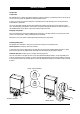
Operating Procedures Tap Operation Safety feature. Zip Hydroboil Plus has a unique safety device designed to reduce the incidence of accidental operation of the tap.
Operating Procedures (setting the controls) DESCRIPTION The Electronic Hydroboil Plus has user interface that consists of a graphic LCD and 4 Capacitive Sensor Switches, (CSS). The user interface gives the current status of the Hydroboil Plus and allows the user to configure it as required. Legend: The user interface is shown below.
Default settings In 2 Hour Sleep Mode, if there has been no water drawn through the tap or no touches of the capacitive switch sensors for two hours, the temperature of the water in the tank will be allowed to drop to and be maintained at 65ºC. (The time taken for the water temperature to drop to 65ºC can be as much as 12 hours depending on ambient conditions and other external factors).
Configuration mode tting operational modes To enter Configuration Mode, press and hold the CSS1 and CSS4 for 10 seconds. The unit enters Configuration Mode and the user can configure the clock as follows. SET SETPOINT Setpoint display To return to Normal Mode, press CSS4. To increment the setpoint, press either CSS2 or CSS3. To step to the next configuration parameter, press CSS1. Note 1: The setpoint moves in a circular fashion. It goes from 98 to 99 to 100 to 65 to 66 etc.
Configuration mode (continued) perational modes CONFIGURE SLEEP MODE Sleep display To return to Normal Mode, press CSS4. To configure sleep mode to kick in after 4 hours, press either CSS2 or CSS3. To step to the next configuration parameter, press CSS1. Note: Configuring Sleep Mode moves in a circular fashion. It goes from 2 hours to 4 hours to OFF and back to 2 hours etc. ENABLE LOW LIGHT SENSOR Daylight saving display To return to Normal Operation, press CSS4.
Spare Parts Item Kit No.
Spare Parts 26 1 23 3 24 2 25 27 4 5 16 3 6 17 7 18 14 11 8 10 9 19 12 22 13 20 21 Zip Hydroboil Plus - Installation & Operating Instructions - 86584UK - February 2008 15 Page 15 of 16
Warranty Information Certain warranties may be implied by law into your contract with Zip. The warranty provided below is additional to these implied warranties and nothing set out below shall limit your statutory rights or rights at law.