
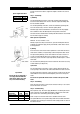
Operating instructions


Page 6 of 16 Zip Hydroboil Plus - Installation & Operating Instructions - 86584UK - February 2008
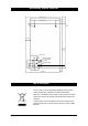
Screws or bolts must be able to support the weight as shown in the chart on
the left.
Step 3 – Connecting
a) Plumbing
For exposed plumbing connection, connect the cold water inlet pipe from the
base of the heater directly to the 15 mm or half-inch compression fittings with
the nuts and olives provided.
For concealed plumbing connections, connect the cold water pipe through the
rear of the chassis using a 15 mm or half-inch capillary elbow.
Cold water pipes must be flushed before connection to the inlet. Any clogging
due to sediment or fines will adversely affect the operation of the heater.
The heater must be installed with an isolating valve which allows it to be isolated
from the mains supply for servicing.
Water pressure requirements:
Minimum - 0.7 bar, maximum - 7 bar.
Warning: If pressure is likely to exceed 7 bar, a pressure limiting valve must be
installed in the cold water supply line. Zip recommends a valve rated at 3.5 bar
for this application.
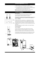
b) Venting
A vent at the base of the heater must be plumbed to a safe visible location as,
under certain conditions, it may discharge cold or boiling water and/or steam.
For exposed vent plumbing, connect vent outlet from the base of heater to a
15 mm or half inch OD pipe which has a continuous fall, is no more than 3
metres long, has no more than 3 right angle bends, and discharges to a waste
water drain.
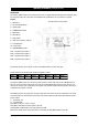
For concealed vent plumbing, direct the vent outlet from the heater rear, using
a visible tundish. (see diag at left)
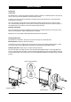
c) Electrical
For concealed electrical connection, connect a power cable through the rear
access opening of the heater to the terminal block within the heater as shown.
For exposed electrical connection, connect the flex to a fused spur on the wall
within 1500 mm of the heater that will adequately cater for the units power
needs.
Do not turn the power ON until the heater is filled to the tap level, with
water.
Step 4 – Assembling
Place the heater case back on to the heater and secure the top 2 case screws.
Secure two bottom case screws.
Step 5 – Commissioning
Check previous steps. Turn water supply ON. Water is now flowing into heater,
check connections for leaks. Wait approximately 5 minutes and check outlet
tap for water. This is achieved by pressing the tap paddle.
Power is only to be turned on when water is available from this outlet.
Turn power ON. After a short period, boiling water will be available and will be
maintained close to boiling point thereafter. Initial heating periods are shown in
the table on the left.
250mm
Wring
Concealed
Vent
Concealed
Inlet
45 mm
Visible Tundish
Vent line
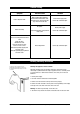
Special Note
Ensure the silicon outlet tube is
correctly positioned within the
outlet nozzle. Failure to do this
may cause internal flooding.
Aprox weight when filled
Installation Procedures
(continued)
Inlet water
temperature
15
°°
C10
°°
C
3.0 Litre models 16 min 17 min
5.0 Litre models 16 min 17 min
7.5 Litre models 23 min 24 min
3.0 Litre models 12.5 kg
5.0 Litre models 16.5 kg
7.5 Litre models 20.5 kg