Quick Start Guide ProFace X [TD] Version: 1.
1 Overview Flash Thermal infrared temperature measurement module Near-infrared flash Camera & palm collector Microphone (Optional) 8-inch touchscreen Tamper switch Speaker Reset button RS232 RS485 Wiegand Out Wiegand In 12V 12V GND GND GND RXD1 TXD1 485B 485A GND 12V +12V GND Power interface WD1 WD0 INWD1 INWD0 GND 12V GND AUX GND SEN GND BUT NO COM NC ALAL+ Network interface 1 Power Auxiliary input Sensor Exit button Lock Alarm
2 Installation Environment Please refer to the following recommendations for installation. 10ft INDOOR USE window ft 6.5 KEEP DISTANCE AVOID GLASS REFRACTION AVOID DIRECT SUNLIGHT AND EXPOSURE KEEP EFFECTIVE DISTANCE 0.3-2.5m 3 Device Installation Install on the wall ① Attach the mounting template sticker to the wall, and drill holes according to the mounting paper. ② Fix the back plate on the wall using wall mounting screws. ③ Attach the device to the back plate.
3 Device Installation Install on the barrier gate Please thread the wire through the bracket before installation. ① Drill a hole on the barrier gate, insert the bracket into the hole and fix it with a nut. ② Adjust the angle of the device.
4 Standalone Installation Smoke detector Alarm Door sensor Exit button Reader Lock TCP/IP PC 5 Door Sensor, Exit Button & Alarm Connection Detector power + - - + Smoke detector Exit button + - Alarm + - Alarm power 4 GND AUX GND SEN GND BUT NO COM NC ALAL+ Door sensor
Lock Relay Connection The system supports Normally Opened Lock and Normally Closed Lock. The NO LOCK (normally unlocked when power-on) is connected with 'NO' and 'COM' terminals, and the NC LOCK (normally locked when power-on) is connected with 'NC' and 'COM' terminals. Take NC Lock as an example below: 1) Device not sharing power with the lock 2) Device sharing power with the lock GND +12V DC12V Maximum 30V 3A input.
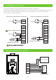
8 Barrier Connection 12V 12V GND GND GND RXD1 TXD1 485B 485A GND 12V Barrier gate 9 RS485 Connection 12V 12V GND GND GND RXD1 TXD1 485B 485A GND 12V +12V GND 485485+ GND 485 reader Note: 485A and 485B can be connected to the barrier gate or the 485 reader, but cannot be connected to the gate and the reader at the same time.
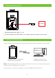
10 Power Connection 12V 3A DC Recommended power supply: 12V - 3A To share the power with other devices, use a power supply with higher current ratings. 11 Ethernet Connection Connect the device and computer software over an Ethernet cable. An example is shown below: ZKBioAccess EP Default IP address : 192.168.1.201 Subnet mask : 255.255.255.0 IP address : 192.168.1.130 Subnet mask : 255.255.255.
12 User Registration When there is no super administrator set in the device, click on to enter the menu. After setting the super administrator, the system will request for the administrator’s verification before entering the menu. For the security purpose, it is recommended to register a super administrator at the first time you use the device. Method1: Register on the device Click on > [User Mgt.] > [New User] to register a new user.
Method 2: Register on ZKBioAccess EP software Please set the IP address and cloud service server address on the device. 1. Click [Access] > [Access Device] > [Device] > [Search Device] to add the device to the software. When the device has set the server address and port, it can be added automatically. Refresh New Delete Export Search Device Search Total Progress 192.168.213.
Method 3: Register on the phone Once ZKBioAccess EP software installed, users could enroll face via browser application on their own mobile phone. 1. Click [Personnel] > [Parameters], input ‘’http://Server address:Port’’ in the QR Code UGL bar. The software will automatically generates a QR code. Scan the QR code or login onto ‘’http://Server address:Port/app/v1/adreg’’ by the mobile phone to register users.
13 Access Control Settings Click on > [Access Control] to enter the access control management interface and set relevant parameters of access control. L 14 Ethernet and Cloud Server Settings Click on > [Comm.] > [Ethernet] to set the network parameters. If the TCP/IP communication of the device is successful, the icon will be displayed in the upper right corner of the standby interface. Click on > [Comm.
15 Detection Management Settings Click on > [System] > [Detection Management] to enter the detection management interface. You can set the value of High temperature alarm threshold. The device will send an alarm prompt when the temperature of the user detected exceeds this value. When the Temperature over the range; access denied is enabled, the user will be forbidden to access, as shown in the following figure.
Note: 1. The effective distance for temperature detection is within 50cm. 2. Recommended for indoor use. 3. Temperature measurement data is for reference only, not for medical use. 4. Remove the mask to register the face, wear a mask to recognize the face, the type of mask, the size of the face covered by the mask, and bangs will affect the facial recognition effect. 5. Facial verification for masked individuals will increase FAR. Palm verification for masked individuals is recommended.
Welcome, admin Area Device Name Status ............... Alarm temperature setting Temperature management Time Area Device Event Point Personnel ID First Name Department Body temperature Real-time monitoring Statistics panel 2020-04-01 14:20:53 Area Name 192.168.1.120 192.168.1.120-1 2 Temperature Raw Record 2020-04-01 14:20:43 Area Name 192.168.1.120 192.168.1.120-1 2 Personnel temperature schedule 2020-04-01 10:50:21 Area Name 192.168.1.120 192.168.1.120-1 2 Status Mask 36.
Method for Enrolling Palm 3 5 0- 0c m Note: 1. Place your palm within 30-50cm of the device. 2. Place your palm in the palm collection area, such that the palm is placed parallel to the device. 3. Make sure to keep space between your fingers.
www.zkteco.eu Copyright©2020 ZKTeco CO., LTD. All rights reserved.