Installation Guide Version: 2.
Important Notes 1. Please read this Installation Guide carefully and contact the Customer Care Service if you have any questions about the installation. 2. To avoid any future service charges that can arise as a result of incorrect installation, it is recommended that installation can be performed by a professional technician prevent any potential service charges that can occur due to incorrect installation. 3.
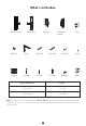
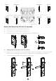
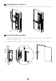
What's in the Box Outdoor Unit Mortise Indoor Unit Strike Plate and Box Stud Cylinder Keys Spindle A Spindle B Spindle C Plug Screw A Screw B Screw C Screw D Metal Pin Cards Screw Door Thickness 45 to 50 mm Screw A 51 to 60 mm Screw B Note: Spindles for door thickness from 45 to 60 mm are included in the standard package. To ensure proper lock operation, please use the specified spindle based on the thickness of your frame.
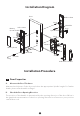
Installation Diagram Door Outdoor Unit Stud Metal Pin Indoor Unit Keys Battery (not included) Spindle A/B Stud Screw C Mortise Cylinder Battery Cover Spindle C Screw B Metal Pin Screw A Screw D Plug Strike Plate and Box Installation Procedure 1 Door Properties A. Measure the Door Thickness Measure the thickness of the door and select the appropriate Spindle length. For further details, please refer the table on Page 1. B.
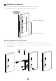
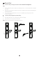
Mortise Strike Plate Mortise Strike Plate Mortise Right Inward Left Inward Mortise Strike Plate Strike Plate Right Outward Left Outward User Location Adjust the Direction of Latch (if needed) 1) Push the reverse block in upward direction. 2) 3) Push the bolt of the latch into the mortise. Rotate the latch bolt to 180° inside the mortise, and release it. C.
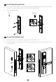
2 Drill Holes on the Door 1) Place the installation template at the desired handle height. 2) Mark the holes to be drilled and drill the marked locations. Center line of handle 60m m Back set Desired handle height 3 Install Mortise and Cylinder 1) Put the Mortise into the hole that was drilled, and secure the Mortise with Screw A. 2) Insert the Cylinder into the Mortise (note the front sides and back sides) and secure it with Screw B.
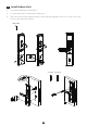
4 Install Spindle and Studs 1) Insert the Spindle A/B into the clutch and insert the Metal Pin from the bottom of the clutch, force the pin apart and bend it to hold the Spindle A/B. 2) Then, install the studs. Stud Metal Pin 5 Install the Outdoor Unit 1) Pass the outdoor unit cable through the top of the cable hole. 2) Pass the Spindle A through the hole of the clutch and the outdoor unit must be close to the entrance.
6 Install Indoor Unit 1) Insert the Metal pin on Spindle C. 2) Connect the cable to the Indoor Unit port. 3) Place the Indoor Unit appropriately on the Mounting Plate. Then use Screw C & Screw D to protect the Indoor Unit.
7 Install Batteries and Cover Insert four Alkaline AA batteries and cover them with the battery cover, and insert the Plug. 8 Install Strike Plate and Box 1) Make sure that the Strike Box is aligned with the latch bolt. Then, use the installation template to drill the holes. 2) Align the Strike Plate and Box with the holes drilled and protect them with Screw A.
9 Physical Test A. Test the lock by rotating the handle and the double locking knob. Note: 1) The front handle can be rotated even when the door is closed, but the door remains unlocked. 2) When the Security knob is turned on, the door remains unlocked even if the handle is rotated from indoor. 3) If push handle downward, the lock close. It is installation problem, please refer to step 5 installation.
User Manual Version: 2.
Important Notes 1. TL600 is an intelligent Smart Lock. If the lock is not installed properly, it may affect the lifetime of the lock. We suggest to install the lock after furnishing. Please prefer a professional technician to install the lock as per our installation standard. 2. Please initialize the lock after installation and set the Administrator immediately to avoid others opening the door illegally. 3. To ensure your security, please check the box of keys when opening the product package. 4.
Product Overview Battery Cover Reset Button Keypad & Card Detection Area Battery Compartments Fingerprint Sensor Handle Handle Security Knob Mechanical Key Hole Double Locking Knob Emergence Power Interface Definitions User Roles: The lock can be handled by two user roles namely Administrator and User. The Administrator has the privilege to access the menu and open the door. The user has the privilege to only open the door. Note: Each user can register ten fingerprints, one password, and one card.
Emergency Charging: The bottom of the outdoor unit is provided with a Micro-USB interface. Use a power bank to charge the lock when it is out of power. Emergency Mechanical Key: The mechanical key is used to open the door when the lock has electronic malfunction. Double Locking: Double locking prevents the lock from being unlocked from the outside. Users can enable it by rotating the double locking knob.
4 Programming the Features through Menu Mode 1) Touch the keypad to activate the lock. 2) Press the # key thrice to access the menu. 3) Verify the administrator's identity with his/her fingerprint or card, or by entering the password then press the # key to confirm. 4) Enter the digit corresponding to the function to be performed by following the audio guide.
Note: 1) The registered password can be of 6 to 12 digits. 2) The currently logged-in administrator cannot delete his/her admin data. 3) Please ignore Hotpot config and OTA function. Quick Start Attention: If the verification is failed for five times, the lock will generate an alarm.
How to connect ZSmart APP? Step 1: Download the ZSmart App and register your Account Open the ZSmart App and log in with your account. If you do not have an account, create an account with your phone number or Email ID. Search the ZSmart App in Apple App Store or Google Play Store or scan the QR Code to download the App to your mobile phone /Tablet. Step 2: Add the Lock to the App Tap the "+" button on the top right corner of the interface and then select the "Smart Lock" option.
Step 3: Add the Wi-Fi Details Select the desired Wi-Fi and enter the Password. Then tap the “Confirm” button. Note: The smart lock only works on 2.4GHz Wi-Fi networks. Step 4: Open Lock Smart Con g Mode Access the lock’s menu, press >> 4 >> 4 >> 1 to open smart config mode. Step 5: Setup Completion Once you see the message “Added successfully” on the mobile app, you can edit the name of smart lock manually. Tap the “Done” button to complete the setup.
Warning: This device complies with Part 15 of the FCC Rules. Operation is subject to the following two conditions: (1) This device may not cause harmful interference, and (2) this device must accept any interference received, including interference that may cause undesired operation. This equipment has been tested and found to comply with the limits for a Class B digital device, pursuant to Part 15 of the FCC Rules.