Cautions Anew locks defined as always in open mode until iris locked once by a IC 550/570 card. Please register an authorized card, a time sync card, and a room card initially for the new lock. The lock is equipped with keys for manual unlocking. Remove the keys from the package and keep them in a safe place. To power on the lock, four alkaline AA batteries (not included) are required. Non alkaline and rechargeable batteries ARE NOT RECOMMENDED.
What'sin Box Liquidator Unit Indoor Unit Mortise Cylinder Spindle A Spindle B Strike Plate and Box Hex Wrench AEA A] ~~ Screw A Screw B Screw C Hex Wrench 8 712mm M5*65mm M5*65mm Note: This lock is ideal for doors with a thickness This lock will nonfiction a door that is thicker than 58 mm. Please contact the salesperson if you have any queries.
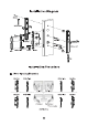
Installation Diagram installation Procedure BE] Door Opening Direction Mortise Strike Plate Strike Plate Mortise on i La. Left inward | Right inward Strike Plate Mortise .
Strike Plate Mortise » Left inward Strike Plate = Left Outward Strike Plate Mortise . ® i Right inward Strike Plate io « Right Outward # Person Location 6085 Mortise Note: Please install the Mortise and Strike Plate according to the above illustration. Adjust the Latch's Direction (if necessary) © Adjustment of 3085 Mortise 1) When you rotate the mortise 180 degrees, the fastener will drop down. 2 3 insert the latch into the mortise. ) ) ) Disentangle the latch by turning it to 180 degrees.
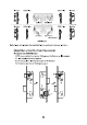
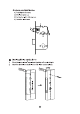
<% Adjustment of 6085 Mortise 1) Push Up the fastener. 2) The latch pops up, 3) Rotate the latch 180 degrees. 4) Push the latch back. FI Drilling Holes on the Door 1) Paste the installation Template at the desired handle height. 2) Mark forth holes to be drilled and drill the marked places.
El Installation the Mortise 1) Insert the mortise into the drilled hole, secure it with Screw A, and make sure the cable is towards the outdoor unit. Vi Screw A 2) Insert the Cylinder, then secure it with Screw B.
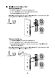
3 Installation the Outdoor Unit “% Method of 3085 Mortise 1) Install the Studs on the back of the Outdoor Unit. 2) insert a Spindle A into the clutch toward Outdoor Unit. 3} Attach the Outdoor Unit to the door. Note: Please pay attention to the point of clutch, the point is at right side when right opening, the point is at left side when left opening. KE Spindle A Studs Right Opening TENN Left Opening + Method of 6085 Mortise 1) install the Studs on the back of the Outdoor Unit.
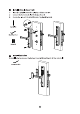
EH Installation Indoor Unit 1} Insert the Sp indie B into the cylinder and turn it to 45°. 2) Connect the battery cable with the ma inboard. 3) Secure the indoor Unit with 2 Screws C by Hex Wrench A. FEN =) Spindle B Me A Trenchancy Screw C I Install Batteries To install batteries, remove the Battery Cover with Hex Wrench B, then reinstall it.
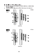
EZ Installation of Strike Plate and Box 13 Make sure that the Strike Box is aligned with the latch bolt. Then, use the Installation Template to drill holes. 2} Align the Strike Plate and Box with the drilled holes and secure them with Screw A.
EJ] Blockbuster Mechanical Key insert one of the key and rotate it to 80° and then press the outdoor unit handle, if the aitch backs up, it means exact. Note: The handier of outdoor unit is always free.
FC Warning: This device complies with Part 15 of the FCC Rules. Operation is subject to the following two conditions: (1) This device may not cause harmful interference, and (2) this device must accept any interference received, including interference that may cause undesired operation. This equipment has been tested and found to comply with the limits fora Class B digital device, pursuant to Part 15 of the FCC Rules.
Zapotec industrial Park, No. 32, industrial Road, Jiangxi Town, Guangdong, China. Phone Fax :+86 755 89602394 www.zkteco.com Copyright A 2022 ZAPOTEC CO, LTD. All Rights Reserved.