R anges & C ooktops Installation Guide and Users Manual
Never sacrifice power for performance with a ZLINE range. Enjoy the luxury of cast iron grills, triple layer insulated glass paneling, and a high-gloss black porcelain cooktop. Utilizing items engineered and crafted in Italy, this range is on the top tier of technology with its advanced features and aesthetic upgrades.
CONTENTS Installation Guide IMPORTANT SAFETY INSTRUCTIONS 1 WARRANTY AND SERVICE 3 BEFORE INSTALLATION 5 INSTALLING THE LEGS 7 INSTALLING THE CHAINS RANGE TOP & DROPIN INSTALLATION 8 INSTALLATION REQUIREMENTS POWER RATING & ELECTRICAL CONNECTION 11 13 WIRING SCHEMATICS 14 GAS CONNECTION 18 GAS CONVERSION PROCEDURE 23 INSTALLATION CHECKLIST 28 FINAL PREPARATION 28 9
CONTENTS Users Manual ROOM VENTILATION 30 COOKTOP COOKING 31 USING THE OVEN 33 MAINTAINING YOUR RANGE 39 CHANGING DOORS 40 TROUBLESHOOTING 41
Thank You We want to thank you for choosing one of our beautiful, professional ranges. We know that you have many brands to choose from and we are thrilled that you have decided to place one of our products in your home. Our appliances are designed according to the strictest safety and performance standards for the North American market. We follow the most advanced manufacturing process. Each appliance leaves the factory after thorough quality inspection and testing.
Location of Appliance Tags The rating tag shows the model and serial number of your range. The tag is located under the front edge of the range cooktop. The tag is visible when the oven door is open.
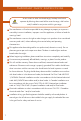
Important Safety Instructions An air curtain or other overhead range/cooktop hood which WARNING operates by blowing downward airflow onto the range, shall not be used/installed in conjunction with this gas range. The manufacturer will not be responsible for any damage to property or to persons caused by incorrect installation, improper use of the appliance, or failure to heed the warnings listed.
Important Safety Instructions Important Safety Information Please read and follow these important instructions for the safety of your home and the people living in it. If the information in this manual is not followed exactly, a fire or WARNING explosion may result causing property damage, personal injury, or death. Do not store or use gasoline or any other flammable substances in the vicinity of this or any other appliance. Never use this appliance as a space heater to heat or warm the WARNING room.
Warranty and Service Warranty and Service All range products carry a one year parts warranty and includes service, if required. Service on all products shall be carried out by industry professionals only. For warranty service, please call customer service. Replacement Parts Only authorized replacement parts may be used in performing service on this appliance. Replacement parts are available from ZLINE. Call 1-614-777-5004. Product Dimensions Internal Dimensions 48” Model: 26.5” W/12.5”W x 18.
Product Dimensions Dropins: Cooktops: Cooktop cut outs: 4
Before Installation This appliance shall only be installed by an authorized professional. The appliance shall be installed in accordance with the standards of the country where it will be installed. The installation of this appliance must conform to local codes and ordinances. In the absence of local codes installation must conform to American National Standards, National fuel Gas code ANSI Z223.1-Latest edition/ NFPA 54 or B 149.1.
Before Installation Room Ventilation An exhaust fan may be used with the appliance; in each case it shall be installed in conformity with the appropriate national and local standards. Exhaust hood operation may affect other vented appliances; in each case it shall be installed in conformity with the appropriate national and local standards. Type of Gas This appliance is shipped from the factory for use with natural gas. For use with propane LP gas, please follow the conversion procedure described on pg.
Installing the Legs The ranges must be used with the legs properly installed. Height-adjustable legs are shipped with the range in a foam container above the range. Installing the Legs 1. Before installing the legs, position the appliance near its final location, as the legs are not suitable for moving the appliance over long distances. 2. After unpacking the range, raise it enough to insert the legs in the appropriate receptacles situated on the lower part of the appliance.
Installing Chains Installing the chains The chains shipped with the range must be properly secured to the rear wall. The height of the bracket from the floor must be determined after the range legs have been adjusted to the desired height and after the range has been leveled. If the chain length is too short to properly secure the range to the rear wall, ask the installer to lengthen it.
Range Top/Dropin Installation Attaching the dropin To prevent liquids from accidentally leaking into the underlying storage space, the appliance is equipped with a special gasket. To apply this gasket, carefully follow the instructions in Fig. 1. Lay out the protective sealing strips along the edges of the opening in the bench top and carefully overlap the strip end. (See Fig. 1). insert the dropin into the bench top opening.
Island Conversion Procedure ISLAND CONVERSION ISLAND PROCEDURE CONVERSION for RT36 and RT48 PROCEDURE for RT36 and RT48 1. On the back side of the range top, remove the UPPER SHEET by unscrewing the two 1. On theholes backbyside the range top, remove theof sides. the UPPER SHEET by unscrewing the two holes by the sides. 1. 1. 2. 2. UP PE 3. PE RS RS HE ET HE ET 3. 2. Lift the UPPER SHEET and flip to the under side. Two screws on each side must be 2. Lift theunscrewed.
Installation Requirements A properly grounded and horizontally-mounted electrical receptacle type NEMA 1450R should be installed no higher than 3” above the floor, no less than 2” and not more than 8” from the left side (facing product); refer to electrical connection section. Gas An agency-approved, properly-sized manual shut-off valve should be installed no higher than 3” above the floor and no less than 2” and no more than 8” from the right side (facing product).
Installation Requirements Cooking Range Front View Side View 13” 30” to 36” to bottom of ventilation hood 18 30” 27 ¹/₂” 6” W opening width location of gas and electrical extends on floor 36-38” to cooking surface 3.23” 3.
Power Rating & Electrical Connection The appliance shall be connected to a single phase electric line rated at 110-120Vac and 60Hz frequency. The true voltage in most homes is usually between these values. Electric Power Rating 220/240 Vac: 12A Max If voltage is less than 220/240, then preheat times may vary.
Wiring Schematics Model: RG30 Model: RG36 14
Wiring Schematics Model: RA30 RED WHITE BROWN GREEN 120/208 V Ac 60Hz 120/240 V Ac 60Hz (LIFT) oven fan (RIGHT) oven fan WIRE CONNECTOR SWITCH FOR THERMOSTAT Heat pipes-up (INSIDE1800/2395 W, OUTSIDE 650/865 W) GROUND WIRE IGNITION ALLUMAGE RA30(RAB30-RAS30)电路图 MICROSWITCH 1 SWITCH FOR ELECTRIC OVEN SNAP THERMOSTAT MICROSWITCH 2 SWITCH MICROSWITCH 3 白色 MICROSWITCH 4 Heat pipes-down 2000/2670W case fan (LIFT) LAMP SWITCH FOR LAMP (RIGHT) LAMP (LIFT) oven fan (RIGHT) oven fan WIRE CONNECT
Wiring Schematics Model: RA48 RED WHITE BROWN GREEN 120/208 V Ac 60Hz 120/240 V Ac 60Hz (LIFT) oven fan (RIGHT) oven fan WIRE CONNECTOR SWITCH FOR THERMOSTAT Heat pipes-up (INSIDE1800/2395 W, OUTSIDE 650/865 W) GROUND WIRE IGNITION ALLUMAGE RA30(RAB30-RAS30)电路图 MICROSWITCH 1 SWITCH FOR ELECTRIC OVEN SNAP THERMOSTAT MICROSWITCH 2 SWITCH MICROSWITCH 3 白色 MICROSWITCH 4 Heat pipes-down 2000/2670W case fan (LIFT) LAMP SWITCH FOR LAMP (RIGHT) LAMP T4NN400NCN Model: RT/RTS (30”) GREEN RED WH
Wiring Schematics RED GREEN WHITE RED GREEN 110~120V- 60Hz RED MICROSWITCH 6 MICROSWITCH 5 MICROSWITCH 4 MICROSWITCH 3 MICROSWITCH 2 MICROSWITCH 1 GROUND WIRE RED 6 MICROSWITCH 5 MICROSWITCH 5 MICROSWITCH 4 MICROSWITCH 3 MICROSWITCH 2 MICROSWITCH 1 GROUND WIRE MICROSWITCH 7 17 WHITE 110~120V- 60Hz T6NN600NCN Model: RT/RTB/RTS (36”) WIRE CONNECTOR IGNITION ALLUMAGE Model: RT/RTS (30”) T7NN700NCN WIRE CONNECTOR IGNITION ALLUMAGE
GAS CONNECTION All gas connections must comply with national and local codes. The gas supply line (service) must be the same size or greater than the inlet line of the appliance. This range uses a ½˝ NPT inlet. Use appropriate sealant on all pipe joints that are resistant to gas. This range can be used with Natural or LP/propane gas. The range is shipped from the factory for use with natural gas.
Gas Connection Manual Shut-Off Valve This valve is not shipped with the appliance and must be provided by the installer. The manual shut-off valve must be installed in the gas service line between the gas hook-up on the wall and the appliance inlet, in position where it can be reached quickly in the event of an emergency. In Massachusetts: A T handle type manual gas shut-off valve must be installed in the gas supply line to this appliance.
Gas Connection Pressure Regulator Since service pressure may fluctuate with local demand, every gas cooking appliance must be equipped with a pressure regulator on the incoming service line for safe and efficient operation. Pressure Regulator The pressure regulator shipped with the appliance has two female threads 34”NPT. The regulator shall be installed properly in order to be accessible when the appliance is installed in its final position.
Gas Connection The gas conversion procedure for this range includes: 1. Pressure Regulator 2. Surface Burners 3. Flame Adjustment The conversion is not finished if all steps are not completed. Before performing the gas conversion, locate the package containing the replacement nozzles, which has a number indicating its flow diameter printed on the body. Consult the table below for matching nozzles to burners. Save the nozzles removed from the range for future use.
Gas Connection 22
Gas Conversion Procedure Step 1: Pressure Regulator The pressure regulator supplied with the appliance is a convertible type pressure regulator for use with Natural Gas at a nominal outlet pressure of 4˝ w.c. or LP gas at a nominal outlet pressure of 11” w.c. and it is pre-assembled from the factory to operate with one of these gas pressure as indicated in the labels affixed on the appliance, package and instruction booklet. To convert the regulator for use with other liquid propane LP gas: 1.
Gas Conversion Procedure Step 2: Surface Burners To replace the nozzles of the surface burners, lift up the burners and unscrew the nozzles shipped with the range using a 7 mm (socket wrench). Replace nozzles using the conversion set supplied with the range. Each nozzle has a number indicating its flow diameter printed on the body. Consult the table on page 21 for matching nozzles to burners.
Gas Oven Conversion Procedure Step 1: Open the oven door and remove the tray and racks. Step 2: Remove the upper burner screw. Step 3: Remove the burner from its connection against the back wall of the oven. Be careful not to scratch or damage the connection wire that will remain connected throughout this procedure. Step 4: Using a 7mm (9/32) tap or socket wrench, remove the nozzle.
Gas Oven Conversion Procedure Step 5: Set the natural gas nozzle aside and replace with the propane nozzle. Screw in and tighten the new nozzle. AR3 Nozzle Step 6: Place the burner vent back into position over the new nozzle in the AR3 slot. Burner Vent Step 7: Secure the burner back in place with the mounting screw that was removed in step 2. Step 8: Follow steps 2 through 7 with the bottom burner. Ensure the nozzles and burners are secured properly.
Gas Oven Conversion Procedure Step 9: 9a. Light one burner at a time and set it to the MINIMUM position (small flame). 9b. Remove the knob. 9c. The range is equipped with a safety valve. Using a small-size flathead screwdriver, locate the choke screw (see diagram below) and turn to the right or left until the burner flame is adjusted to desired minimum. 9d. Make sure that the flame does not go out when switching quickly from the MAXIMUM to the MINIMUM position.
Installation Checklist 1. Is the range mounted on its legs? 2. Is the back guard securely connected? 3. Have the chains been properly installed? 4. Does the clearance from the side cabinets comply with the manufacturers’ direction? 5. Is the electricity properly grounded? 6. Is the gas service line connected following the directions of the manufacturer? 7. Have all the proper valves, stoppers, and gaskets been installed between the range and the service line? 8.
Users Manual 29
Room Ventilation Any child or adult can tip the range, verify that the chains are working. Ensure the chains are reattached when the range is moved. WARNING Do not operate the range without the chains in place. Failure to do so can result in serious injury or serious burns to children or adults. The use of a gas cooking appliance generates heat and humidity in the room where it is installed. Proper ventilation in the room is needed.
COOKTOP COOKING Surface Burner Operation - Electric Ignition To activate the electric ignition, simply turn the control knob counter-clockwise to maximum power, then press the knob in to start the flow of gas and the ignition spark. The spark will be released at the metal tip of the white ceramic pin located on the side of the burner. Once the flame is on, release the control knob gently. If the flame turns off, simply repeat the above procedure.
COOKTOP COOKING Be sure to set all worktop/oven/broiler burner controls to the OFF position after each use of the appliance. Symbols: Oven Functions Selector Cooktop Functions Selector OFF OFF Max 450 400 250 300 350 Maximum temperature setting/recommended control knob position for burner ignition.
Using the Oven Oven Function Selectors - RA/RAB/RAS models The temperature dial must be set to the preferred temperature and the baking dial must be set to the preferred cooking function. Symbols: Oven Functions Selector OFF Max 450 Symbols: 400 Oven Functions Selector 350 250 300 OFF High Bake Conv. Broil Conv.
Using the Oven Oven Function Selectors - RG/RGB models The timer must be set to “ON” or a timed option with the temperature dial set to the preferred temperature for the oven to function. Please note that the timer dial sits to the right when the oven is OFF. Symbols: Oven Functions Selector OFF, then 180. The timer stops when going from OFF to ON.
Using the Oven Using Pans Correctly 1. Always ensure that the bottom and handles of pans do not protrude over the worktop. 2. When cooking with flammable fat, such as oil, do not leave the range unattended. 3. Use pots of the appropriate size on each burner following the indication of the diagram below. 4. To avoid overflow when boiling liquids; turn knob to the minimum heat. 5. Always use pots with matching lids. 6. Dry the bottoms of pans before operation. 7.
Using the Oven Placement of Oven Racks Continued 5. DO NOT TOUCH HEATING ELEMENTS OR INTERIOR SURFACE OF OVEN. Heating elements may be hot even though they are dark in color. Interior surfaces of an oven become hot enough to cause burns. During and after use, do not touch, or let clothing or other flammable materials come into contact with the heating elements or interior surfaces of the oven until they have had sufficient time to cool.
Using the Oven Oven Racks The ranges are equipped with commercial grade shelves and an enamel cooking tray. Shelves are mounted on the appropriate guides situated on the sides of the oven compartment. Insert the shelf between the top and bottom guide in any of the 5 positions available. To keep the oven as clean as possible, cook on the tray. When available, always follow recipe book directions. Personal experience will help to determine any variation in the values reported in the table.
Using the Oven High Bake/Preheat: This setting is the optimum setting for roasting and baking, suggested use if for baking at temperatures 325-525 degrees. High Bake will use both the bottom element and the center ring of the top element for even cooking and optimal oven temperatures. Use this setting for preheating the oven- High Bake is designed to get the oven to optimal temperature as quickly as possible.
Maintaining Your Range Cleaning Your Range During cleaning operation, never move the appliance from its original installation position. Never use abrasive cleaners! Scratches on the stainless WARNING steel surfaces are permanent. Do NOT clean the range when hot! Cleaning after Installation: Use a stainless steel cleaning product or wipe to eliminate the glue residues of the protection film after removal.
Changing Doors 1. Install the pins into slots on each hinge (pins not included.) 2. Carefully lift the door out of the range. 3. Uninstall the kick plate by unscrewing the four screws in the corners of the kick plate. There are two at the top and two at the bottom on each side. Have another helper tilt the range to unscrew the bottom screws. 4. Slide out the kick plate. 5. Slide in the new kick plate. 6. Screw in the four screws to secure the kick plate. 7. Hook the new range door onto the range.
Troubleshooting Oven Problem Possible Cause and/or Remedy Range does not function Range is not connected to electrical power. Check power circuit breaker, wiring, and fuses. Broil does not work Temperature control knob is rotated too far past broil position (500°F); preheating indicator will light intermittently. Igniter does not work The circuit is tripped, fuse is blown, or range is not connected to power.
Kitchen and Bath Three Locations: 350 Parr Circle Reno, NV 89512 916 Delaware Avenue Marysville, OH 43040 319 Rowland Mill Road Bruceton, TN 38317 www.zlinekitchen.