R ange H ood Installation Guide and Users Manual
Often the center attraction of a kitchen, ZLINE range hoods can add surprising value to your property, by providing both an impressive, aesthetic look to your home, excellent ventilation, and additional kitchen lighting. ZLINE range hoods blend superior performance with elegant design. ZLINE motors are incredibly powerful, yet quiet compared to the competitors. This is achieved through the highly durable steel-on-steel construction and unique centrifugal design.
CONTENTS IMPORTANT SAFETY INSTRUCTIONS 1 BUTTON/CONTROL PANEL OPERATION 3 WALL RANGE HOOD INSTALLATION 4 CROWN MOLDING INSTALLATION 9 DESIGNER WALL RANGE HOOD INSTALLATION 12 ISLAND RANGE HOOD INSTALLATION 17 DESIGNER ISLAND RANGE HOOD INSTALLATION 21 UNDER CABINET INSTALLATION 25 RANGE HOOD INSERT INSTALLATION 29 REMOTE BLOWER INSTALLATION 31 HOW TO CHANGE PARTS 33 TROUBLESHOOTING AND FAQ 44 MOUNTING SPECIFICATIONS 51
WARRANTY AND DISCLAIMER Proper Venting Regulations Please verify with your local, city, and state regulations on the proper venting method for your hood. Many agencies have CFM rating specifications for your hood, as well. You may have to purchase additional items on your own to vent the hood in accordance with your local city and state specifications. Our ZLINE dual motor range hoods come with an 8” metal transition piece without a backdraft damper and a piece of 4’ metal ducting.
Warranty and Disclaimer Warranty Three Year Parts Warranty: For three years from the date of original purchase, we will provide free of charge, non-consumable replacement parts for the components that failed due to manufacturing defects. Subject to the conditions and limitations set forth below at its option, either repair or replace any part of its products that prove defective by reason of improper workmanship or material. Repaired parts or replacement products will be provided by www.therangehoodstore.
WARRANTY AND DISCLAIMER This warranty is valid in the United States. It is non-transferable and applies only to the purchaser and does not extend to subsequent owners of this product, any applicable implied warranties, including the warranty of merchantability are limited in duration to a period of express warranty as provided herein beginning with the date of original purchase at retail and no warranties, whether express or implied shall be applied to this product.
Important Safety Instructions Read all instructions before installing and operating this appliance. The installation instructions in this manual are intended for qualified installers, service technicians, or persons with similar qualified background. Installation and electrical wiring must be done by qualified professionals and in accordance with all applicable codes and standards, including first-rated construction. DO NOT attempt to install this appliance yourself.
Important Safety Instructions All electrical wiring must be properly installed, insulated, and grounded. Old duct work should be cleaned or replaced, if necessary, to avoid the possibility of a grease fire. Check all joints on duct work to insure proper connection, all joints should be properly taped. Use this unit only in the manner intended by the manufacturer. If you have any questions, contact the vendor.
Button Control Panel Operational Manual Button/Control Panel Operation Button functions Power: Turn ON/OFF the range hood and activate power-off delay timer. Light: Turn ON/OFF (Some models will have bright, dim, and OFF settings.) Blower Speed Indicator: Shows current blower (motor) speed (1-4). 1- Low Speed: Light frying/boiling. 2 - Medium Speed: Frying/wok cooking/heavy boiling. 3 - High-Grilling: Intensive frying and wok cooking.
Wall Range Hood Installation Installation Tutorial Video 4
Wall Range Hood Installation Please unpack your range hood when it is delivered and inspect to ensure all parts are included. Parts Supplied 1. Main Hood with All Lights and Button 5. Flexible Duct (for 6” or 8”) Banks Pre-Installed 6. Packet of Screws and Anchors 2. Adjustable Stainless Steel Chimney Cover 7. Top Mounting Bracket 3. Transition Piece (for 6” or 8”) 8. Grease Cup 4.
Wall Range Hood Installation The recommended height to install your hood is 30˝ minimum and 36˝ maximum above the cooktop. For Outdoor (304 Series) hood installation, the unit must be installed at a minimum of 36˝ above the grill. Step 1 Find the center of the wall where you are installing the hood. Make sure there is sufficient bracing to hold the weight of the hood. Mark your center line and measure out from the center to find your two mounting points.
Wall Range Hood Installation Step 5 Install the transition piece securing it with the screws provided. Figure 4 Step 6 Make your electrical and ducting connections. Try and minimize the use of elbows. More elbows and longer runs create higher static pressure. The hood comes with a grounded three prong plug that can either be direct wire or plugged into a 20 amp circuit. The cord is 45” long. Figure 5 Step 7 Connect the ducting to the transition piece using a ring to hold it into place.
Wall Range Hood Installation Before installing baffle filters, make sure that you insert the clear, plastic grease cup under the motor blower. Step 8 Install the two part chimneys on top of the hood. Slide the inside section up until the vertical vent slots are visible, attach top portion to mounting bracket with screws. Secure lower chimney portion to the hood with screws provided. Figure 7 Step 9 Install the grease cup by sliding into brackets located at the bottom of the motor.
Crown Molding Installation If using a crown molding, follow instructions before attaching ducting and chimney sections. Step 1 Attach crown molding bracket to ceiling using hardware provided. Step 2 Attach ducting and electrical connections. Step 3 Attach chimney sections to the range hood, then connect to crown molding bracket. Step 4 Slide crown molding onto crown bracket and secure into place.
Crown Sound Installation Electric Power Rating Frequency: 110V/50 Hz Power: 10W Step 1 Installation Tutorial Video Attach crown molding bracket to ceiling using hardware provided. Figure 1 Figure 1 Step 2 Attach ducting and electrical connections. Plug the speakers into an outlet behind the chimney. When the connection is successful, a chime will sound.
Crown Sound Installation Step 3 Extend the chimney up to the transformer. Slide the crown molding onto the crown bracket and secure into place. The crown should cover the gap. Ensure that it installs properly and is level. Figure 3 Figure 3 Step 4 Open the phone’s Bluetooth settings and find “ZLINE Audio.“ When the connection is successful, a chime will sound. Figure 4 Figure 4 11 Bluetooth crown moldings carry a one year parts warranty. Replacement speakers are available from ZLINE.
Designer Wall Range Hood Installation Installation Tutorial Video 12
Designer Wall Range Hood Installation Please unpack your range hood when it is delivered and inspect to ensure all parts are included. Parts Supplied 1. Main Hood with All Lights and Button 6. Packet of Screws and Anchors Banks Pre-Installed 7. Top Mounting Bracket 2. Chimney 8. Crown Molding Bracket 3. Transition Piece (for 6” or 8”) 9. Crown Molding 4. Baffle Filters 10. Grease Cup 5.
Designer Wall Range Hood Installation The recommended height to install your hood is 30˝ minimum and 36˝ maximum above the cooktop. For Outdoor (304 Series) hood installation, the unit must be installed at a minimum of 36˝ above the grill. Step 1 Find the center of the wall where you are installing the hood. Make sure there is sufficient bracing, such as wooden beams, to hold the weight of the hood. Mark your center line and measure out from the center to find your two mounting points.
Designer Wall Range Hood Installation Step 5 Make your electrical and ducting connections. Try and minimize the use of elbows. More elbows and longer runs create higher static pressure. The hood comes with a grounded three prong plug that can either be direct wire or plugged into a 20amp. circuit. The cord is 45” long. Figure 4 Step 6 Install the transition piece securing it with screws provided. Figure 5 Step 7 Connect the ducting to the transition piece using ring to hold into place.
Designer Wall Range Hood Installation Step 8 Find the center of the wall where you are installing the hood. Make sure there is sufficient bracing to hold the weight of the hood. Mark your center line and measure out from the center to find your two mounting points. Make sure your mounting points are level when you mark them. It is recommended to install the hood directly into wood supports.
Island Range Hood Installation 17 Installation Tutorial Video
Island range Hood Installation Please unpack your range hood when it is delivered and inspect to ensure all parts are included. Parts Supplied 1. Main Hood with All Lights and Button 6. Packet of Screws and Anchors Banks Pre-Installed 7. Top Mounting Bracket 2. Chimney 8. Crown Molding Bracket 3. Transition Piece (for 6” or 8”) 9. Crown Molding 4. Baffle Filters 10. Grease Cup 5.
Island Range Hood Installation The recommended height to install your hood is 30˝ minimum and 36˝ maximum above the cooktop. For Outdoor (304 Series) hood installation, the unit must be installed at a minimum of 36˝ above the grill. Step 1 Locate the center above the stove where the hood is to be installed. Ensure that the bracket will be secured to solid wood backing. Attach mounting bracket to the ceiling. Figure 1 Step 2 Attach the transition piece and ducting to top of the hood.
Island Range Hood Installation Step 6 Slide chimney pieces over the angle iron on the hood. Pull the electrical plug to the top of the chimney sections. Figure 4 Step 7 Lift the hood to attach the angle iron to the ceiling bracket. Use screws provided to attach. Step 8 Make your electrical and ducting connections. Use rigid ducting wherever possible. Try and minimize the use of elbows. More elbows and longer runs create higher static pressure. No more than two to three elbows are recommended.
Designer Island Hood Installation 21 Installation Tutorial Video
Designer Island Hood Installation Please unpack your range hood when it is delivered and inspect to ensure all parts are included. Parts Supplied 1. Main Hood with All Lights and Button 6. Packet of Screws and Anchors Banks Pre-Installed 7. Top Mounting Bracket 2. Chimney 8. Crown Molding Bracket 3. Transition Piece (for 6” or 8”) 9. Crown Molding 4. Baffle Filters 10. Grease Cup 5.
Designer Island Hood Installation The recommended height to install your hood is 30˝ minimum and 36˝ maximum above the cooktop. For Outdoor (304 Series) hood installation, the unit must be installed at a minimum of 36˝ above the grill. Step 1 Locate the center above the stove where the hood is to be installed. Ensure that the bracket will be secured to solid wood backing. Attach mounting bracket to the ceiling. Figure 1 Figure 1 Step 2 Attach the transition piece and ducting to top of the hood.
Designer Island Hood Installation Step 6 Slide chimney pieces over the angle iron on the hood. Pull the electrical plug to the top of the chimney sections. Figure 4 Step 7 Lift the hood to attach the angle iron to the ceiling bracket. Use screws provided to attach. Step 8 Figure 4 Make your electrical and ducting connections. Use rigid duct wherever possible. Try and minimize the use of elbows. More elbows and longer runs create higher static pressure.
Under cabinet Installation 25 Installation Tutorial Video
Under cabinet Installation Preparation Decide the location of the venting pipe from the hood to the outside. Check hood for clearance. A straight, short vent run will allow the hood to perform more efficiently. Try to avoid as many transitions, elbows, and long runs as possible. This may reduce the performance of the hood. For installing under the cabinet with recessed bottom, attach 4-inch wide wood filler strips (not provided) on each side.
Under cabinet Installation Step 5 Draw electrical wires through cabinet access opening, center the hood beneath the cabinet. Step 6 Align hood-mounting brackets to the screws on the wall and hook hood into place. Tighten screws to secure hood to the wall. Step 7 Connect ducting.
Under-Cab Rear Ducting Conversion If you need to convert your under cabinet range hood to rear ducting, use the following instructions. Please note that converting the undercab to rear ducting is a modification of the standard hood and part of the installation process. It is recommended that the hood is inspected before this procedure. Only certain undercab models allow for rear ducting. Contact us at 1-614-777-5004 for more information on compatible models.
Range Hood Insert Installation 29 Installation Tutorial Video
RANGE HOOD INSERT INSTALLATION When installing a range hood insert, it is recommended to install the unit at a minimum of 30˝ Figure 1 from the cooktop. For outdoor range hood inserts it is recommended to install the unit at a minimum of 36˝ from the grill top. Step 1 Figure 1 Unpack contents of the hood. Attach transition piece and ducting to the top of the range hood insert. Figure 1 and 2 Step 2 Figure 2 Using L brackets and screws provided, attach L brackets to each side of the insert.
REMOTE BLOWER INSTALLATION When installing your new remote blower type range hood, follow the instructions for the type of hood you are installing. Remote blowers are available with wall, island, under cabinet, and insert range hoods. Make certain to connect the electrical cord to the hood and plug the blower motor in to test the unit. Step 1 Run duct work into the area that you will install the remote from your range hood. Step 2 Fasten ducting to the range hood using a hose clamp and silver/duct tape.
REMOTE BLOWER INSTALLATION The Remote Blower is designed for our Remote Range Hoods. This unit is installed remotely in the interior of your home. This provides venting, but with reduced noise. T85 Remote Blower—Single Motor (This Blower must be used with Remote Blower Hood) Airflow 280 / 400 / 580 / 900 (CFM) Noise Level: 1.2 / 2.6 / 4.2 / 6.5 (Sones) Dimensions: 26.14 x 14.
How to Change Parts How to Change Out the Button Panel 1. Remove baffle/aluminum filters. 2. Locate back of button panel. 3. Remove screws from each side of the button panel. 4. Disconnect button panel from cord connecting to circuit board. Note: Never work on or clean the range hood while power is ON. Always unplug the unit or switch the electrical breaker to the off position.
How to Change Parts How to Replace the Circuit Board: 1. Turn the power off at the breaker and unplug the Range Hood. 2. Remove all screws from the top of the circuit board cover. 3. Take a picture of the wiring layout (this will help you put the circuit board back together properly). 4. Remove the wiring connected to the circuit board. 5. Remove the screws from the circuit board. 6. Replace the wiring and screws to reassemble the new circuit board per the diagram below.
How to Change Parts Replacing the Light Bulbs in Your Range Hood: 1. Remove baffles. 2. Squeeze the old LED light casting out until it falls out of the socket. 3. Disconnect the plug wires from the light wire. 7. Reconnect the LED plug into the light wire. 8. Press light assembly into the socket. Note: Never work on or clean the range hood while power is ON. Always unplug the unit or switch the electrical breaker to the off position.
How to Change Parts Professional Series Baffle Filter Change: Covering Models 696, 697, 697i (Island), KECOM, KECOMi (Island), 695, 698, and 721 Inserts Professional series hoods are equipped with 2 removable dishwasher safe baffle channels (one for series 695 and 698 inserts) that the baffle filters rest in. To install the channels, place inside the hood, right under the front and back edges of the hood. The channel is kept in place by installation pieces on the sides and back of the baffle channel.
How to Change Parts Baffle Filter: The baffle filter is equipped with a knob. To remove from the hood, pull back toward the wall and down.
How to Change Parts Change/Replace Capacitor: 1. Remove screws from the circuit board cover. 2. Remove screws from compactor. 3. Remove both wired connections from the capacitor. 4. Connect new capacitor with wire connectors. 5. Replace screws in cover. 6. Repeat operation if dual motor. Note: Some units have more than one motor. If you have a unit with dual motors, there will be two capacitors. Note: Never work on or clean the range hood while power is ON.
How to Change Parts Replace or Change Charcoal Filters: It is recommended to direct vent the hood whenever possible. If your situation does not allow for a direct vent install, carbon filters are available to recirculate the air through your hood. Filter Support Screws 1. Remove the stainless steel or aluminum filters from the bottom of the hood. 2. Locate the existing raised support screws on each side of the internal motor(s). 3.
How to Change Parts How to Clean, Install, or Replace the Grease Cup: A removable grease cup is provided to catch any excess grease at the bottom of the motor. Remove it every 2 to 3 months, wash it, then re-install it. Note: Never work on or clean the range hood while power is ON. Always unplug the unit or switch the electrical breaker to the off position.
How to Change Parts Replace or Change Transformer: 1. Remove the screws from the transformer. 2. Remove the two connections to the lights. 3. Remove the two wired connections from the circuit board (you must remove the circuit board cover). 4. Install the new connections from your new transformer (be certain the correct wires are connected). 5. Reinstall the cover for the circuit board with screws. 6. Replace all screws in the transformer. 7. Reconnect the lights to the transformer.
How to Change Parts Single Motor Electrical Diagram: 42
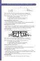
How to Change Parts Dual Motor Electrical Diagram: 43
Troubleshooting and FAQ Where are ZLINE products manufactured? All ZLINE products are manufactured in ZLINE facilities overseas, including: Germany, Italy, and China. Are ZLINE range hoods considered type 1 or type 2? Type 1 - Range hoods that are used with appliances that produce grease and smoke. Are ZLINE products meant for residential or commercial use? Residential use. Why is my range hood white? This is a protective layer that is placed on all of our range hoods to prevent shipping damage.
Troubleshooting and FAQ No Power 1. Check electrical connections. 2. Check that all connections to the circuit board are secure. 3. If problem still exists, the circuit board needs to be replaced. How loud is the range hood? A sone is measure of loudness, the higher the sone rating, the louder the sound of the hood. The sound of one sone is comparable to that of a quiet refrigerator. Keep in mind that other factors such as the size of the blowers can affect the loudness of the range hood.
Troubleshooting and FAQ How many amps are produced on the highest fan setting? For dual motors, it is up to 3.317 amps on the highest fan setting. For single motors, it is 1.678 amps. What type of motor is in the range hoods? Our hoods have a squirrel cage motor. Is the width of my range hoods description, the actual size? No, the actual size of the range hood will be slightly less than the generic description of the range hood. For instance: a 30˝ range hood will most likely be 29-7/8˝.
Troubleshooting and FAQ My hood is operating, but the air is moving slower than normal. Check the filter for buildup and clean or replace it if needed. If the difficulty still persists, check for obstructions in the ductwork. A common obstruction is buildup in the roof or wall cap, such as: bird nests or other debris. My hood is making a rattling noise. This is probably attributed to one of the following: 1.
Troubleshooting and FAQ How many devices can the Bluetooth speakers sync to at a time? Only 1 device can sync at a time. What is the decibel rating of the Bluetooth speakers? Up to 100 decibels. What is the range of the speakers? What’s the maximum distance for the connection to work? Up to 50 feet. If the connection is weak, move closer to the speakers or remove obstacles that are between the device and the speakers. “ZLINE Audio” won’t appear in the Bluetooth settings.
Troubleshooting and FAQ Hood Is Not Pulling Was the unit plugged in and was the fan checked before installation? What distance is the hood mounted above the cook top? Indoor (30”-36”), outdoor (36”-40”) Is the range hood width the correct size for the cook top? Outdoor units should be at least 1 size larger, if not 2 Does the hood have enough BTU output in relationship to either their gas or electric stove cook top? BTU output per burner/100 - for gas Wattage output per burner/10 - for electric Are the baff
Troubleshooting and FAQ Noisy Motor Were the fan speeds checked fan speeds prior to installation? Is the ducting clear? Check to make sure motor is attached to housing Is the 6” back draft damper on transition piece functioning properly (760 CFM hood?) Does it open when the hood is engaged? If it is stuck, it will sound like motor noise but it’s really the damper Was a damper installed on the roof or side vent? Check that the damper is fully functioning by engaging the hood and checking if it opens and clos
MOUNTING SPECIFICATIONS C B A D 51 Model Numbers A B C D 432-30 19 116 " 20 1116 " 29 3 4 " 8" 432-36 19 116 " 26 1116 " 35 3 4 " 8" 432-42 19 116 " 32 1116 " 41 3 4 " 8" 432-48 19 116 " 38 1116 " 47 3 4 " 8"
MOUNTING SPECIFICATIONS C B A D Model Numbers A B C D 433-30 19 116 " 20 1116 " 29 3 4 " 8" 433-36 19 116 " 26 1116 " 35 3 4 " 8" 433-42 19 116 " 32 1116 " 41 3 4 " 8" 433-48 19 116 " 38 1116 " 47 3 4 " 8" 52
MOUNTING SPECIFICATIONS C B A D 53 Model Numbers A B C D 435-30 19 116 " 20 1116 " 29 3 4 " 8" 435-36 19 116 " 26 1116 " 35 3 4 " 8" 436-30 19 116 " 20 1116 " 29 3 4 " 8" 436-36 19 116 " 26 1116 " 35 3 4 " 8"
MOUNTING SPECIFICATIONS C B A D Model Numbers A B C D 455-30 17 1116 " 9 1116 " 13 5 16 " 6" 455-36 17 1116 " 9 1116 " 13 5 16 " 8" 455-42 17 1116 " 9 1116 " 13 5 16 " 8" 455-48 17 1116 " 9 1116 " 13 5 16 " 8" 54
MOUNTING SPECIFICATIONS C B A D 55 Model Numbers A B C D 476-30 17 1116 " 9 1116 " 13 5 16 " 6" 476-36 17 1116 " 9 1116 " 13 5 16 " 8" 476-42 17 1116 " 9 1116 " 13 5 16 " 8" 476-48 17 1116 " 9 1116 " 13 5 16 " 8"
MOUNTING SPECIFICATIONS C B A D Model Numbers A B C D 477-30 17 1116 " 9 1116 " 13 5 16 " 6" 477-36 17 1116 " 9 1116 " 13 5 16 " 8" 477-42 17 1116 " 9 1116 " 13 5 16 " 8" 477-48 17 1116 " 9 1116 " 13 5 16 " 8" 56
MOUNTING SPECIFICATIONS C B A D 57 Model Numbers A B C D 488-30 19 116 " 20 1116 " 29 3 4 " 8" 488-36 19 116 " 26 1116 " 35 3 4 " 8" 488-42 19 116 " 32 1116 " 41 3 4 " 8" 488-48 19 116 " 38 1116 " 47 3 4 " 8"
MOUNTING SPECIFICATIONS C B A D Model Numbers A B C D 587-R-30 15 3 16 " 9 9 16 " 11 1116 " 8" 587-R-36 15 3 16 " 9 9 16 " 11 1116 " 8" 587-R-42 15 3 16 " 9 9 16 " 11 1116 " 8" 587-R-48 15 3 16 " 9 9 16 " 11 1116 " 8" 58
MOUNTING SPECIFICATIONS C B A D 59 Model Numbers A B C D 587-30 15 3 16 " 9 9 16 " 11 1116 " 6" 587-36 15 3 16 " 9 9 16 " 11 1116 " 6" 587-42 15 3 16 " 9 9 16 " 11 1116 " 6" 587-48 15 3 16 " 9 9 16 " 11 1116 " 6"
MOUNTING SPECIFICATIONS C B A D Model Numbers A B C D 597-R-30 15 3 16 " 9 9 16 " 11 1116 " 8" 597-R-36 15 3 16 " 9 9 16 " 11 1116 " 8" 597-R-42 15 3 16 " 9 9 16 " 11 1116 " 8" 597-R-48 15 3 16 " 9 9 16 " 11 1116 " 8" 597-R-54 15 3 16 " 9 9 16 " 11 1116 " 8" 597-R-60 15 3 16 " 9 9 16 " 11 1116 " 8" 60
MOUNTING SPECIFICATIONS C B A D 61 Model Numbers A B C D 597-30 15 3 16 " 9 9 16 " 11 1116 " 6" 597-36 15 3 16 " 9 9 16 " 11 1116 " 6" 597-42 15 3 16 " 9 9 16 " 11 1116 " 6" 597-48 15 3 16 " 9 9 16 " 11 1116 " 6" 597-54 15 3 16 " 9 9 16 " 11 1116 " 6" 597-60 15 3 16 " 9 9 16 " 11 1116 " 6"
MOUNTING SPECIFICATIONS C B A D Model Numbers A B C D 654-30 17 116 " 9 58 " 13 5 16 " 6" 654-36 17 116 " 9 58 " 13 5 16 " 8" 654-42 17 116 " 9 58 " 13 5 16 " 8" 654-48 17 116 " 9 58 " 13 5 16 " 8" 62
MOUNTING SPECIFICATIONS C B A D 63 Model Numbers A B C D 655-R-30 17 1116 " 9 1116 " 13 5 16 " 8" 655-R-36 17 1116 " 9 1116 " 13 5 16 " 8"
MOUNTING SPECIFICATIONS C B A D Model Numbers A B C D 655-30 17 1116 " 9 1116 " 13 5 16 " 6" 655-36 17 1116 " 9 1116 " 13 5 16 " 8" 655-42 17 1116 " 9 1116 " 13 5 16 " 8" 655-48 17 1116 " 9 1116 " 13 5 16 " 8" 64
MOUNTING SPECIFICATIONS C B A D 65 Model Numbers A B C D 656-30 17 1116 " 9 1116 " 13 5 16 " 6" 656-36 17 1116 " 9 1116 " 13 5 16 " 8" 656-42 17 1116 " 9 1116 " 13 5 16 " 8" 656-48 17 1116 " 9 1116 " 13 5 16 " 8"
MOUNTING SPECIFICATIONS C B A D Model Numbers A B C D 667-30 17 1116 " 9 1116 " 13 5 16 " 6" 667-36 17 1116 " 9 1116 " 13 5 16 " 8" 667-42 17 1116 " 9 1116 " 13 5 16 " 8" 667-48 17 1116 " 9 1116 " 13 5 16 " 8" 667-54 17 1116 " 9 1116 " 13 5 16 " 8" 667-60 17 1116 " 9 1116 " 13 5 16 " 8" 66
MOUNTING SPECIFICATIONS C B A D 67 Model Numbers A B C D 685-30 19 116 " 20 1116 " 29 3 4 " 8" 685-36 19 116 " 26 1116 " 35 3 4 " 8" 685-42 19 116 " 32 1116 " 41 3 4 " 8" 685-48 19 116 " 38 1116 " 47 3 4 " 8"
MOUNTING SPECIFICATIONS C B A D Model Numbers A B C D 686-30 19 116 " 20 1116 " 29 3 4 " 8" 686-36 19 116 " 26 1116 " 35 3 4 " 8" 686-42 19 116 " 32 1116 " 41 3 4 " 8" 686-48 19 116 " 38 1116 " 47 3 4 " 8" 68
MOUNTING SPECIFICATIONS C B A D 69 Model Numbers A B C D 687-R-30 19 5 16 " 14 14 " 17 7 8 " 8" 687-R-36 19 5 16 " 14 14 " 17 7 8 " 8" 687-R-42 19 5 16 " 14 14 " 17 7 8 " 8" 687-R-48 19 5 16 " 14 14 " 17 7 8 " 8"
MOUNTING SPECIFICATIONS C B A D Model Numbers A B C D 687-30 19 5 16 " 14 14 " 17 7 8 " 8" 687-36 19 5 16 " 14 14 " 17 7 8 " 8" 687-42 19 5 16 " 14 14 " 17 7 8 " 8" 687-48 19 5 16 " 14 14 " 17 7 8 " 8" 70
MOUNTING SPECIFICATIONS C B A D 71 Model Numbers A B C D 696-36 14 18 " 7 1116 " 11 14 " 6" 696-R-36 14 18 " 7 1116 " 11 14 " 8"
MOUNTING SPECIFICATIONS C B A D Model Numbers A B C D 697-R-30 17 1116 " 9 1116 " 13 5 16 " 8" 697-R-36 17 1116 " 9 1116 " 13 5 16 " 8" 697-R-42 17 1116 " 9 1116 " 13 5 16 " 8" 697-R-48 17 1116 " 9 1116 " 13 5 16 " 8" 72
MOUNTING SPECIFICATIONS C B A D 73 Model Numbers A B C D 697-30 17 1116 " 9 1116 " 13 5 16 " 6" 697-36 17 1116 " 9 1116 " 13 5 16 " 8" 697-42 17 1116 " 9 1116 " 13 5 16 " 8" 697-48 17 1116 " 9 1116 " 13 5 16 " 8" 697-54 17 1116 " 9 1116 " 13 5 16 " 8" 697-60 17 1116 " 9 1116 " 13 5 16 " 8"
MOUNTING SPECIFICATIONS C B A D Model Numbers A B C D 8632-30 27 7 8 " 9 12 " 11 13 16 " 6" 8632-36 27 7 8 " 9 12 " 11 13 16 " 8" 8632-42 27 7 8 " 15 1116 " 18 " 8" 8632-48 27 7 8 " 15 1116 " 18 " 8" 74
MOUNTING SPECIFICATIONS C B A D 75 Model Numbers A B C D 9597-30 15 3 16 " 9 9 16 " 11 1116 " 6" 9597-36 15 3 16 " 9 9 16 " 11 1116 " 6"
MOUNTING SPECIFICATIONS C B A D Model Numbers A B C D 9667-30 17 1116 " 9 1116 " 13 5 16 " 6" 9667-36 17 1116 " 9 1116 " 13 5 16 " 8" 76
MOUNTING SPECIFICATIONS C B A D 77 Model Numbers A B C D 9697-30 17 1116 " 9 1116 " 13 5 16 " 6" 9697-36 17 1116 " 9 1116 " 13 5 16 " 8"
MOUNTING SPECIFICATIONS C B A D Model Numbers A B C D ART2-30 15 3 16 " 9 7 16 " 11 1116 " 6" ART2-36 15 3 16 " 9 7 16 " 11 1116 " 6" 78
MOUNTING SPECIFICATIONS C B A D 79 Model Numbers A B C D BS655N-30 17 1116 " 9 1116 " 13 5 16 " 6" BS655N-36 17 1116 " 9 1116 " 13 5 16 " 8" BS655N-42 17 1116 " 9 1116 " 13 5 16 " 8" BS655N-48 17 1116 " 9 1116 " 13 5 16 " 8"
MOUNTING SPECIFICATIONS C B A D Model Numbers A B C D BSKBN-24 11 3 4 " 7 116 " 9 18 " 6" BSKBN-30 11 3 4 " 7 116 " 9 18 " 6" BSKBN-36 11 3 4 " 7 116 " 9 18 " 6" BSKBN-42 11 3 4 " 7 116 " 9 18 " 6" BSKBN-48 11 3 4 " 7 116 " 9 18 " 6" 80
MOUNTING SPECIFICATIONS C B A D 81 Model Numbers A B C D BSKEN-30 12 3 4 " 9 9 16 " 11 5 8 " 6" BSKEN-36 12 3 4 " 9 9 16 " 11 5 8 " 6" BSKEN-42 12 3 4 " 9 9 16 " 11 5 8 " 6" BSKEN-48 12 3 4 " 9 9 16 " 11 5 8 " 6"
MOUNTING SPECIFICATIONS C B A D Model Numbers A B C D KB-24 11 3 4 " 7 116 " 9 18 " 6" KB-30 11 3 4 " 7 116 " 9 18 " 6" KB-36 11 3 4 " 7 116 " 9 18 " 6" KB-42 11 3 4 " 7 116 " 9 18 " 6" KB-48 11 3 4 " 7 116 " 9 18 " 6" 82
MOUNTING SPECIFICATIONS C B A D 83 Model Numbers A B C D KB2-30 13 3 8 " 7 116 " 9 18 " 6" KB2-36 13 3 8 " 7 116 " 9 18 " 6" KB2-42 13 3 8 " 7 116 " 9 18 " 6" KB2-48 13 3 8 " 7 116 " 9 18 " 6"
MOUNTING SPECIFICATIONS C B A D Model Numbers A B C D KE-30 12 3 4 " 9 9 16 " 11 5 8 " 6" KE-36 12 3 4 " 9 9 16 " 11 5 8 " 6" KE-42 12 3 4 " 9 9 16 " 11 5 8 " 6" KE-48 12 3 4 " 9 9 16 " 11 5 8 " 6" 84
MOUNTING SPECIFICATIONS C B A D 85 Model Numbers A B C D KF-36 12 " 7 116 " 9 18 " 6" KF1-30 13 5 8 " 8 12 " 10 12 " 6" KF1-36 13 5 8 " 8 12 " 10 12 " 6" KF2-30 159 16 " 8 12 " 10 12 " 6" KF2-36 159 16 " 8 12 " 10 12 " 6"
MOUNTING SPECIFICATIONS C B A D Model Numbers A B C D KL2-30 11 7 16 " 7 116 " 9 18 " 6" KL2-36 11 7 16 " 7 116 " 9 18 " 6" KL2-42 11 7 16 " 7 116 " 9 18 " 6" KL2-48 11 7 16 " 7 116 " 9 18 " 6" 86
MOUNTING SPECIFICATIONS C B A D 87 Model Numbers A B C D KL3-30 12 3 4 " 7 116 " 9 18 " 6" KL3-36 12 3 4 " 7 116 " 9 18 " 6" KL3-42 12 3 4 " 7 116 " 9 18 " 6" KL3-48 12 3 4 " 7 116 " 9 18 " 6"
MOUNTING SPECIFICATIONS C B A D Model Numbers A B C D KN-30 12 3 4 " 9 9 16 " 11 5 8 " 6" KN-36 13 7 16 " 9 9 16 " 11 5 8 " 6" 88
MOUNTING SPECIFICATIONS C B A D 89 Model Numbers A B C D KN6-30 12 7 8 " 9 9 16 " 11 5 8 " 6" KN6-36 13 9 16 " 9 9 16 " 11 5 8 " 6"
MOUNTING SPECIFICATIONS C B A D Model Numbers A B C D KZ-30 12 7 16 " 9 9 16 " 11 5 8 " 6" KZ-36 13 5 16 " 9 9 16 " 11 5 8 " 6" 90
Kitchen and Bath Three Locations: 350 Parr Circle Reno, NV 89512 916 Delaware Avenue Marysville, OH 43040 319 Rowland Mill Road Bruceton, TN 38317 www.zlinekitchen.