Wall Mount Chimney Style Island Mount Chimney Style Wall Mount Professional Style Insert Mount Professional Style
Installation: 4
Table of Contents Wall Hood Installation pgs. 6-8 Island Installation pgs. 9-11 Professional Wall Hood Installation pgs. 12-13 Professional Island Hood Installation pgs. 14-15 Professional Insert Hood Installation pg. 16 Range Hood Operation Controls pg. 17 Charcoal Filter Installation (vent free) pg. 18 Filter Installation Baffle/Aluminum Standard Hoods pg. 19 Professional Series Baffle Filter and Channel pg. 20 Installation Motor Diagrams and Exploded Parts Views pg.
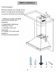
Wall Installation Parts Supplied: Please unpack your range hood when it is delivered and inspect to ensure all parts are included. 1. Main Hood with all lights and button banks preinstalled. 2. Adjustable Stainless Chimney Cover 3. Flexible duct (not pictured) 4. Packet of screws and anchors 5.
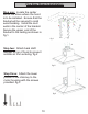
Seven Easy Steps to Installing Wall Hoods Step one: Find the center of the wall where you are installing the hood. Make sure there is sufficient bracing to hold the weight of the hood. Mark your center line and measure out from center to find your two mounting points. Make sure your mounting points are level when you mark them. It is recommended to install the hood directly into wood supports. fig 1 center line 1 fig.
Step 5: Make your electrical and ducting connections. Use 6” rigid duct wherever possible. Try and minimize the use of elbows. More elbows and longer runs create higher static pressure. The hood comes with a grounded three prong plug that can either be direct wired or plugged into a 20 amp. circuit. fig. 4 fig. 4 Step 6: Install the 2 part chimneys on top of the hood by sliding the inside section up until the vertical vent slots are visible.
Island Installation Parts Supplied: Please unpack your range hood when it is delivered and inspect to ensure all parts are included. 1. Main Hood with all lights and button banks preinstalled. 2. Adjustable Stainless Chimney Cover 3. Flexible duct (not pictured) 4. Packet of screws and anchors 5.Island style mounting bracket 6.
Five Easy Steps to Installation Step one: Locate the center above the stove where the hood is to be installed. Ensure that the bracket will be secured to solid wood backing. Install the duct work in the center of the bracket. Secure the upper end of the bracket to the ceiling as shown in fig.1. fig.1 4 Step two: Attach back draft damper to top of hood to prevent outside air from entering. fig.2 fig.2 Step three: Attach the lower portion of the chimney to the motor housing with the screws provided. fig.
Step four: Attach the duct to the top of the back draft damper. Place the chimney sections over the lower bracket section and on top of the main unit. Pull the plug to the top of the chimney sections. Attach lower bracket to upper bracket at desired height using screws provided. fig.4 4 fig.4 Step 5: Make your electrical and ducting connections. Use 6” rigid duct wherever possible. Try and minimize the use of elbows. More elbows and longer runs create higher static pressure.
Professional Series Wall Installation Step one: Find the center of the wall where you are installing the hood. Make sure there is sufficient bracing to hold the weight of the hood. Mark your center line and measure out from center to find your two mounting points. Make sure your mounting points are level when you mark them. It is recommended to install the hood directly into wood supports.
Step six: Mount the top chimney mounting bracket centering it above the hood. fig.5 Step seven: Install the 2 part chimneys on top of the hood by sliding the inside section up until the vertical vent slots are visible. Then put both pieces on top of the hood and secure the lower portion with the provided screw at the bottom. fig. 6 Step 8: Slide the upper portion up and over the top mounting bracket aligning the holes and securing with the screws provided. fig.
Professional Series Island Installation Step one: Position your mounting plate centered above your range. Mark the mounting holes. Take the mounting plate down and screw your mounting screws into place. fig.1 Step two: Measure how far off the range you would like to mount the hood. Adjust the brackets provided to the desired height. Connect the top mounting plate, mounting legs, and the main hood using the screws provided. fig 2.
Step three: Take the chimney sections and separate slightly to reveal the vent slots. Next take the hood and slide the top mounting bracket over the mounting screws and slide back into position. fig 3. Make your electrical and duct connections at this point using 8 inch rigid ducting wherever possible. Step four: Tighten the top mounting screws, securing the top mounting plate to the ceiling. fig 4. Step five: Slide the inner chimney up over the top mounting plate securing with two screws provided.
Professional Series Insert Installation Unpack the contents of the hood and decide which way you would like to install the hood. There are several ways to install the hood. L bracket mounting screw are provided for convenience. See Figure 4.
Range Hood Operations 17
Filter Installations It is recommended to direct vent the hood whenever possible. If your situation does not allow for a direct vent install carbon filters are available to recirculate the air through your hood.
Baffle Filter The baffle filter is equipped with a spring loaded handle. To remove from the hood pull back toward the wall and down. Release The baffle filter can also be opened for easy cleaning. To open unscrew the cylindrical handle and separate the layers to clean.
Professional Series Baffle Installation Covering Models: 696 / 697 / 697 Island / KECOM / KECOM Island / 695, 698, 721 inserts / The following diagrams illustrate filters specific to the professional series of range hoods and inserts: Professional series hoods are equipped with 2 removable dishwasher safe baffle channels (one for series 695 & 698 inserts) that the baffle filters sit into.
Electrical Diagram Single Motor Plug Motor r ove xC it Bo u Circ ard t Bo rcui Ci ank nB Butto Ligh Ground t Tr ans form er Capacitor Separate Diagram Puck Light Puck Light 21
Electrical Diagram Double Motor Plug Cir ard t Bo cui ank on B Butt Tra ns ver Co tB cui Cir d oar ors acit Cap ors Mot diagram sep.
Motor Diagram 23
Double Motor Diagram 24
Grease cup installation: A removable grease cup is provided to catch any excess grease at the bottom of the motor. Remove every 2-3 months wash and re-install.
The Range Hood Store 2276 Westbrooke Drive Clolumbus , OH 43228