
Installation Guide and User Manual

6
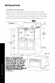
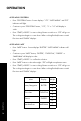
CLEARANCES & DIMENSIONS
MICROWAVE DRAWER ME A SUREMENTS
Dimensions shown in Figure 1 must be used. Given dimensions provide minimum clearance. Locate
electrical outlet in the shaded area in the upper left-hand corner of the cutout (also see Figure 3) Contact
surface must be solid and level. The floor of the opening should be constructed of plywood strong
enough to support the weight of the oven.
Figures 1 & 2 contain Microwave Drawer
measurements for reference in planning the
drawer’s location. This Microwave Drawer can be
installed below any electric or gas wall oven. It
can also be installed using an electrical outlet in
an adjacent cabinet within the area where the
p
provided electrical cord can reach. The power
cord access hole inside the cabinet should have
a minimum diameter of 1 ” and be free of
all sharp edges. ALWAYS allow for sufficient power
cord length to the electrical outlet in order
to prevent tension.
1
/
2
2
Figure 1
Figure 2
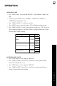
CLEARANCES & DIMENSIONS
MICROWAVE DR AWER MEA SUREMENTS
Dimensions shown in Figure 1 must be used. Given dimensions provide minimum clearance. Locate
electrical outlet in the shaded area in the upper left-hand corner of the cutout (also see Figure 3) Contact
surface must be solid and level. The floor of the opening should be constructed of plywood strong
enough to support the weight of the oven.
Figures 1 & 2 contain Microwave Drawer
measurements for reference in planning the
drawer’s location. This Microwave Drawer can be
installed below any electric or gas wall oven. It
can also be installed using an electrical outlet in
an adjacent cabinet within the area where the
p
provided electrical cord can reach. The power
cord access hole inside the cabinet should have
a minimum diameter of 1 ” and be free of
all sharp edges. ALWAYS allow for sufficient power
cord length to the electrical outlet in order
to prevent tension.
1
/
2
2
Figure 1
Figure 2
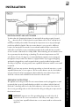
CLEARANCES AND DIMENSIONS
Dimensions shown in the figure below must be used. Given dimensions provide
minimum clearance. Locate electrical outlet in the shaded area in the upper left-hand
corner of the cutout. Contact surface must be solid and level. The floor of the opening
should be constructed of plywood strong enough to support the weight of the oven.
INSTALLATION
Clearances & Dimensions