IP Camera User Manual For further help, please visit www.zmodo.
Preface Dear customer, thank you for choosing to purchase and use our IP camera products. This series of IP monitoring product is the integrated IP network camera which is researched for network video surveillance monitoring. The series includes network bullet camera, network IR bullet camera, and network dome camera, etc. High performance, monolithic SOC chip is utilized as media processor which integrates video capture, compress and transmission. Standard H.
® Contents 1. PRODUCT INTRODUCTION ...................................................................................................................2 1.1 BRIEF INTRODUCTION .....................................................................................................................2 1.2 MAIN FEATURES ..............................................................................................................................2 1.3 INSTALLATION STATEMENT ............................................
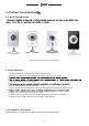
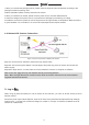
® 1. Product Introduction ▇▅▃ 1.1 Brief Introduction Figure 1-1 Network IP Camera and Its Cable Ports 1.2 Main Features * The highest pixels for100 W, 4M frame rate, real-time image * Supports up to Max three video streams: One 720P, One VGA, One QVGA; * Automatic snapshot in all circumstance * Build-in WEB browser supports IE access * Support multiple user simultaneously, multi-level management ensures high system security.
® 1.When you received the package product, please check the equipment and accessories according to the packing list inside the packing case. 2.Before installation please carefully read this user manual. 3.When you install the IP camera, please close the power source of all the related devices. 4.Check the voltage of the power source, to prevent device damage by mismatching of voltage. 5.Installation environment: please do not use equipment under high humidity or temperature.
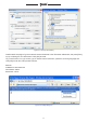
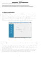
® Figure 2-1 Security Level Setting Install ActiveX and plugins: Type the network camera IP address in the IE browser address bar, and press [Enter] to pop out dialog box of install ActiveX. Click [OK] to install. Log in and Preview: In Login screen, type in network camera username, password, choosing language and click [OK] to enter the video preview interface. Default: IP Address: 192.168.0.
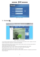
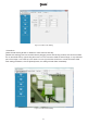
® Figure 2-3 Login Interface 3. Preview ▇▅▃ Figure 3-1 Real-time Preview Interface In the real-time preview interface, the user can control the video channel switch, record, snapshot, full screen preview, image process, image color, and direction configuration. [Video channel] Double Click the channel number to open the video channel to view image, right click and choose "Close" to close the video channel.
® [Image process] The object of image processing includes brightness use mouse to drag the slider to set these items, as figure 3-2. , contrast , saturation , [Color and direction configuration] Image color can be black and white or color, the image can be mirrored or reversed as figure 3-3. [PTZ Control] PTZ operations such as up, down, left and right, and lens operations such as varies Zoom, focal length, and Iris, as figure 3-4.
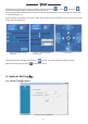
® [Video files packing time] Set the video file packing time, [Video/captured file storage directory] Set file path for local recording and capture. After configuration is finished, click [Submit] button, the configuration will take effect immediately. 4.2 Remote configuration 4.2.1 Video Setting Character Overlay [Title] Name of video channel will be shown on the up left of the image, maximum 16 characters. Click the check box and it will display OSD.
® Figure 4-3 Video Code Setting *Video Block [Video shield switch] Enable or disable the video shield functionality [Shield area setting] User can set shield area by dragging mouse with left key pressed, and cancel the shield box on the shield area by right clicking the mouse. You can choose to shield the whole image, or only shield the part of the image. It can mask up to four areas. You can right click the shield box to cancel this areas’ shield.
® 4.2.2 Network Parameter *Wired Setting [DHCP] If the router allows DHCP functionality, select DHCP. The IP Camera will obtain IP address automatically from the router. If the router does not allow for DHCP functionality, then the IP address must be obtained manually. [IP address] Set wired cable IP address of IP camera device. [Subnet mask] Default: 255.255.255.
® Figure 4-6 IPC WIFI Network Setting Click on “add” or double click on an existing network, open ”WIFI Wireless Network Settings” dialog box as the below figure shows: Figure 4-7 Wifi Hotspot Setting If the user entered this screen by double clicking, a network will be assigned automatically. If the user entered this screen by clicking “Add”, the user has to type in network name, choose a corresponding encryption mode, and type in the password. Click .Connect.
® connect to a wireless network. After saving all parameters, click the [Submit] button, the setting will take effect immediately. Now pull out network cable, you can access the IP network camera via Wifi. Note: WIFI setting only works to those types with WIFI function. Wired network and wi-fi network should not be set in the same network segment. WIFI mode supported by IP Camera: 802.11b/g protocol(small power WiFi type) 802.
® Figure 4-9 PPPOE Parameters Setting *UPnP (Auto Port Mapping) [UPnP] If in LAN it has server with UPNP functionality, enable this function, the server will automatically forward the set port to public network. [Web mapping port] Set the web port which will be mapping to the server. [Video mapping port] Set the digital video port which will be mapping to the server [Mobile phone mapping port] Set the mobile phone port which will be mapping to the server.
® Note: Port mapping can be selectable between 1024~65535. It can't be repeated. *Email Figure 4-11 Email parameters setting This menu is used to set Email address and related parameter of alarm email. [SMTP server] send email server address, such as SMTP server of Google email box: smtp.gmail.com. [Receive Email address] Email address to receive the email. [Send Email address] Email address to send email. [SMTP password] Log in password for the email box. [Email title] The title of sending email.
® [FTP server] IP address or HTTP network address of FTP server. [FTP port] Port of FTP server, default port is 21. [User] User name of the FTP Server. [Password] Password of the FTP Server. After setting all parameters, click the [Submit] button, the setting will take effect immediately. Figure 4-12 FTP parameters setting *DDNS Figure 4-13 DDNS parameter setting Note: It is only necessary to setup DDNS settings on your NVR, please refer to Part 1; section 2.3.3.
® 4.2.3 Video Setting 4.2.3.1 Video Loop Figure 4-14 Video Loop Setting [Loop Video] Click loop video, when the storage of SD card is full, system will overwrite automatically to continue recording. 4.2.3.2 Video Plans Figure 4-15 Record Type and Record Time Setting [Type] Three types of recording types to choose: Schedule recording, Alarm triggered recording and motion triggered recording.
® [Week/Time] You can choose one day from Monday to Sunday, or choose everyday in the week, also there is a time period for you to choose. You need to click the time check to enable the time selection. After setting all parameters, click the [Submit] button, the setting will take effect immediately. 4.2.4 Alarm Setting Figure 4-16 Motion Detection Setting [Time] Set the protection time of motion detection. It can set detail time period of everyday, up to four time periods.
® Figure 4-17 Version Information Figure 4-18 System Time Setting 4.2.6 Advanced Setting 4.2.6.1 User Management Each IP camera can be set up to have up to 15 users. Admin is the system default super user and cannot be deleted, but the admin password can be changed. User's authority is as following. Super-User authority: operate and set all the function and parameter of IP camera Common user authority: The common user is allowed to view video, adjust their password and delete their own account.
® Figure 4-19 User Management Interface Note: The default user after leaving factory is admin, the password is blank. Both user names and passwords are case sensitive. 4.2.6.2 Periodic Maintenance Figure 4-20 Periodic Maintenance Setting [Periodic maintaining] Choose to open periodic maintenance and set maintenance time, detailed maintenance time on everyday can be configured.
® [Reboot device] Click this button to reboot the device. Note: Periodic maintenance and reboot the device will need to wait for 30 seconds to restore video surveillance. 4.2.6.3 Software Update Figure 4-21 Software Update [Update] Click "..." to browse for the correct update file (application file: IPC-APP, Please not change the file name), click "Update". During the update, it will display update information. After update finished, IP Camera will reboot automatically.
® 5. Appendix ▇▅▃ Appendix 1 Specification Type of Parameter Camera VGA Network Camera 720P Network Camera Sensor 1/3" CMOS sensor 1/4" CMOS sensor Pixel 1280(H)*720(V) 640(H)× 480(V) Picture procession Brightness Brightness, contrast, saturation Power 12 V DC @ 600 mA 12 V DC @ 300 mA Network interface RJ45 10/100M, with Indicator light. RJ45 10/100M, with Indicator light.
® Appendix 3 Port Forwarding & Applying for a Free DDNS Domain Service For a complete interactive guide that details how to setup your NVR to be accessible from outside internet networks, please go to www.zmodo.com/network *NVR DDNS Brief Introduction DDNS dynamic DNS means real-time analysis to a fixed domain and dynamic public network IP address of IP camera. All internet users can visit this IP camera through a certain fixed domain that they have setup through our free DDNS service located at zmododns.
® 22
® b. Create domain name(s) for use with your device(s) Once signed in, you will need to add a domain. This will be the address used to access your device. Each account can request up to 5 domains for use with multiple devices at different IP addresses.
® Enter the desired domain name into the blank and hit submit. If the name is available, the user will be informed of a successful domain creation. Otherwise, the user will need to choose a different name. Step 2. Configure the NVR to use zmododns. *The NVR must be actively connected to the internet prior to setting up dynamic DNS a. In the NVR, navigate to "Configure system settings”, then "Configure network settings”, then click on the "DDNSSettings”. b. Choose "zmododns” from the server drop down menu.
® Step 3. Access device via domain name or zmododns.com The user may access his/her device directly via the domain registered (i.e. http://zmodoexample.zmododns. com) Zmododns.com will also have the latest updated public IP address for each of the domains on the user's account. The log in interface is easy and intuitive, and will remember the user's session (no need to log in again on subsequent visits). Once logged in, the user will be presented with links to his/her domains.
® Step 4. Port mapping setting of D-Link router Type in the IP address of router in browser, to log in the main interface of router management. 1.Enter the USERNAME and PASSWORD for your router when prompted. If you are not sure what your router password is, please locate your router onwww.routerpasswords.com If the default password provided bywww.routerpasswords.com does not successfully log you into your router, please call your Internet Service Provider to find out your router's USERNAME and PASSWORD.
® 3. To make sure your ports have been successfully opened, navigate to: www.yougetsignal.com From there click on Port Forwarding Tester.
® You will need to check each port for connectivity using this tool. Enter 80 into the PORT NUMBER field, then click CHECK. You should receive the folling notation: PORT80 is OPEN on XXX.XXX.XXX.XXX Note: The remote access that you see is your IPC’ external address. This is the IP address you will see when you access your IPC via other different computers. Please write this down. If the port is open, then you can visit remotely the IP camera via DDNS domain name at : http://jerry123.zapto.
Lifetime Customer Support US-based Tech Support: 866-551-6881 24/7 Live Support on www.zmodo.