
User Manual

1
© Copyright 2011 Zoeller Co. All rights reserved.
INSTALLATION INSTRUCTIONS
RECOMMENDED MODELS
P/N 151797
Notice to installing contractor: Instructions must remain with installation.
SECTION: 6.10.002
FM2676
1011
Supersedes
New
PREINSTALLATION CHECKLIST - ALL INSTALLATIONS
DATE INSTALLED:
MODEL NUMBER:
1. Inspect your pump. Occasionally, products are damaged during shipment. If the unit is damaged, contact your dealer before using. DO NOT remove the test plugs in the cover nor the motor housing.
2. Carefully read the literature provided to familiarize yourself with specic details regarding installation and use. These materials should be retained for future reference.
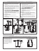
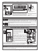
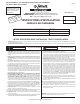
NOTICE: VENT HOLE FOR
CHECK VALVE
SEE #3 IN CAUTION SECTION
BELOW AND #4 ON PAGE 3
EFFLUENT*/SUMP/DEWATERING SEWAGE
49 / 53 / 57 Series, 98 Series 264 Series
137 Series, 151 / 152 / 153 Series 266 / 267 / 268 Series
CAUTION
SEE BELOW FOR
LIST OF CAUTIONS
SEE BELOW FOR
LIST OF WARNINGS
1. Make certain that the receptacle is within the reach of the pump’s power supply cord. DO NOT
USE AN EXTENSION CORD. Extension cords that are too long or too light do not deliver sufcient
voltage to the pump motor. But, more important, they could present a safety hazard if the insulation
were to become damaged or the connection end were to fall into the sump.
2. Make sure the pump electrical supply circuit is equipped with fuses or circuit breakers of
proper capacity. A separate branch circuit is recommended, sized according to the “National
Electrical Code” for the current shown on the pump nameplate.
3. Testing for ground. As a safety measure, each electrical outlet should be checked for ground
using an Underwriters Laboratory Listed circuit analyzer which will indicate if the power, neutral and
ground wires are correctly connected to your outlet. If they are not, call a qualied licensed electrician.
4. For Added Safety. Pumping and other equipment with a 3-prong grounded plug must be connected
to a 3-prong grounded receptacle. For added safety the receptacle may be protected with a ground-
fault circuit interrupter. When a pump needs to be connected in a watertight junction box, the plug
can be removed and spliced to the supply cable with proper grounding. For added safety this circuit
may be protected by a ground-fault circuit interrupter. The complete installation must comply with
the National Electrical Code and all applicable local codes and ordinances.
5. FOR YOUR PROTECTION, ALWAYS DISCONNECT PUMP FROM ITS POWER SOURCE BEFORE
HANDLING. Single phase pumps are supplied with a 3-prong grounded plug to help protect you
against the possibility of electrical shock. DO NOT UNDER ANY CIRCUMSTANCES REMOVE
THE GROUND PIN. The 3-prong plug must be inserted into a mating 3-prong grounded receptacle.
If the installation does not have such a receptacle, it must be changed to the proper type, wired
and grounded in accordance with the National Electrical Code and all applicable local codes and
ordinances. Three phase pumps require motor starting devices with motor overload protection. See
FM0486 for duplex installations.
6. The tank is to be vented in accordance with local plumbing code. Pumps must be installed in
accordance with the National Electrical Code and all applicable local codes and ordinances. Pumps
are not to be installed in locations classied as hazardous in accordance with National Electrical
Code, ANSI/NFPA 70.
7. “Risk of electrical shock” Do not remove power supply cord and strain relief or connect conduit
directly to the pump.
8. Installation and servicing of electrical circuits and hardware should be performed by a qualied
licensed electrician.
9. Pump installation and servicing should be performed by a qualied person.
10. Risk of electric shock - These pumps have not been investigated for use in swimming pool and
marine areas.
11. According to the state of California (Prop 65), this product contains chemicals known to the state
of California to cause cancer and birth defects or other reproductive harm.
1. Check to be sure your power source is capable of handling the voltage requirements of the motor,
as indicated on the pump name plate.
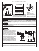
2. The installation of automatic pumps with variable level oat switches or nonautomatic pumps using
auxiliary variable level oat switches is the responsibility of the installing party and care should be
taken that the tethered oat switch will not hang up on the pump apparatus or pit peculiarities and
is secured so that the pump will shut off. It is recommended to use rigid piping and ttings and the
pit be 18" or larger in diameter.
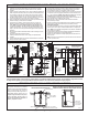
3. Information - vent hole purpose. It is necessary that all submersible sump, efuent, and sewage
pumps capable of handling various sizes of solid waste be of the bottom intake design to reduce
clogging and seal failures. If a check valve is incorporated in the installation, a vent hole (approx.
3/16") must be drilled in the discharge pipe below the check valve and pit cover to purge the unit
of trapped air. Trapped air is caused by agitation and/or a dry basin. Vent hole should be checked
periodically for clogging. The 53 / 57, and 98 Series pumps have a vent located in the pump housing
opposite the oat, adjacent to a housing lug, but an additional vent hole is recommended. The vent
hole on a High Head application may cause too much turbulence. You may not want to drill one.
If you choose not to drill a vent hole, be sure the pump case and impeller is covered with liquid
before connecting the pipe to the check valve and no inlet carries air to the pump intake. NOTE:
THE HOLE MUST ALSO BE BELOW THE BASIN COVER AND CLEANED PERIODICALLY. Water
stream will be visible from this hole during pump run periods.
4. Pump should be checked frequently for debris and/or build up which may interfere with the oat “on”
or “off” position. Repair and service should be performed by Zoeller Pump Company Authorized
Service Station only.
5. Dewatering and efuent sump pumps are not designed for use in pits handling raw sewage.
6. Maximum operating temperature for standard model pumps must not exceed 130°F (54°C).
7. Pump models 266, 267, 268, and 137 must be operated in an upright position. Do not attempt to
start pump when tilted or laying on its side.
8. Do not operate a pump in an application where the Total Dynamic Head is less than the minimum
Total Dynamic Head listed on the Pump Performance Curves.
REFER TO WARRANTY ON PAGE 2.
NOTE: Pumps with the “UL” mark and pumps with the “US” mark are tested to UL Standard UL778.
CSA Certied pumps are certied to CSA Standard C22.2 No. 108.
Product information presented
here reects conditions at time
of publication. Consult factory
regarding discrepancies or
inconsistencies.
MAIL TO: P.O. BOX 16347 • Louisville, KY 40256-0347
SHIP TO: 3649 Cane Run Road • Louisville, KY 40211-1961
(502) 778-2731 • 1 (800) 928-PUMP • FAX (502) 774-3624
visit our web site:
www.zoeller.com
®
Your Peace of Mind is Our Top Priority
®
* Efuent systems should specify that pumps should not handle solids exceeding ¾” in order to prevent large solids from entering leeching elds, mound systems, etc. (Model 49
and 70 Series have 3/8” solids capability. 50, 90, 140, 145/4145, 151, 371 and 372 Series have ½”, 130 Series has 5/8”, 152, 153 and 160/4160/180/4180 and 373 models have ¾”.)
Where code permits, sewage pumps can be used for efuent systems. Non-automatic pumps with external-level controls are recommended for septic tank efuent applications.