
User Manual

3
© Copyright 2011 Zoeller Co. All rights reserved.
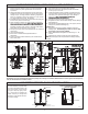
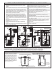
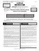
On some installations it may be desirable
to install an independent hanger for the
level control switches to avoid possible
hang ups on the pumps, piping, valves,
etc. Float hangers are available from
Zoeller Company on Catalog Sheet
FM0526 or can be fabricated from stan-
dard pipe and ttings.
SUGGESTED METHODS OF FLOAT INSTALLATION
TYPICAL FLOAT HANGER ON CONCRETE PITS
OR SEPTIC TANK RISERS
TYPICAL FLOAT HANGER ON STEEL COVER PITS
ACCESS COVER
STANDARD PIPE
FLANGE
PVC OR LIGHT WEIGHT
STAINLESS STEEL PIPE
PEA GRAVEL
TYPICAL FLOAT HANGER ON CONCRETE PITS
OR SEPTIC TANK RISERS
10-1457 FLOAT TREE
WITH 3 FLOATS SHOWN
SK1217
SK1218
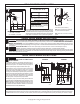
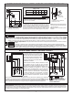
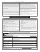
RECOMMENDED INSTALLATION FOR ALL APPLICATIONS
All installations must comply with all applicable electrical and plumbing codes, including, but not limited to, National Electrical Code, local, regional, and/or state plumbing
codes, etc. Not intended for use in hazardous locations.
(1) Electrical wiring and protection must be in accordance with National
Electrical Code and any other applicable state and local electrical
requirements.
(2) Install proper Zoeller unicheck (combination union and check valve),
preferably just above the basin to allow easy removal of the pump for
cleaning or repair. On sewage, efuent or dewatering, if high head or
below cover installation is required use 30-0164 on 1½" pipe, 30-0152
on 2" pipe and 30-0160 on 3" pipe. See (4) below.
(3) All installations require a basin cover to prevent debris from falling into
the basin and to prevent accidental injury.
(4) When a Unicheck is installed, drill a 3/16" dia. hole in the discharge
pipe even with the top of the pump. NOTE: THE HOLE MUST ALSO
BE BELOW THE BASIN COVER AND CLEANED PERIODICALLY.
(High Head unit see #3 under “Caution” on front page). Water stream
will be visible from this hole during pump run periods.
(5) Securely tape or clamp power cord to discharge pipe, clear of the oat
mechanism(s).
(6) Use full-size discharge pipe.
(7) Basin must be in accordance with applicable codes and
specications.
(8) Pump must be level and oat mechanism(s) clear of sides of basin
before starting pump.
(9) Basin must be clean and free of debris after installation.
(10) Gate Valve or Ball Valve to be supplied by installer and installed
according to any and all codes.
(11) Locate oat switches as shown in sketches. The best place for the
“off” point is above the motor housing and positioned 180° from the
inlet. Never put “off” point below discharge on pump (Sewage &
Efuent only). NOTE: FOR AUTOMATIC PUMPS, USE
DEWATERING INSTALLATION SKETCH.
(12) Gas tight seals required to contain gases and odors.
(13) Vent gases and odors to the atmosphere through vent pipe (Sewage
& Dewatering only).
(14) Install Zoeller Pump Stand (Model 10-2421) under pump to provide a
settling basin. (Efuent & Dewatering only.)
For Efuent Only:
(15) Wire pump to power through a Zoeller watertight junction box or
watertight splice. NOTE: Watertight enclosure is a must in damp
areas. See No. 8 on front page of FM0732.
(16) Refer to SSPMA Efuent Sizing Manual for determining “on” - “off”
switches.
(17) Septic tank risers must be used for easy pump and lter access.
NOTE: Double seal pumps offer extra protection from damage caused by
seal failure.
TYPICAL SEWAGE INSTALLATION
SK290
100 mm (4”)
OF GRAVEL
Always refer to
FM0551 and/or
SSPMA recom-
mended sewage
pump installation
and maintenance.
TYPICAL EFFLUENT INSTALLATION
SK291
WW1
EFFLUENT
FILTER
See FM0531,
FM0732 & FM1420
for alarms, controls
& junction boxes
TYPICAL DEWATERING INSTALLATION
SK292
TURN
ON
TURN
OFF
1
2
3
7
9
14
8
6
4
5
10
12
13
10 cm (4") OF GRAVEL
MINIMUM
457mm X 610mm
(18"X24" BASIN.)
LARGER DEPTHS
MAY BE
REQUIRED.
See FM0531, FM0732 & FM1420 for alarms,
controls & junction boxes