Global Distribution Zonda Hobby Technologies Electronic Limited Official Website: www.zondahobby.com / www.zondahobby.com.
Foreword Thank you for choosing GWY Product. To help you to understand and use this AH6T Transmitter, We hope you reading this manual carefully before operate. To learn more information, please visit our official website:www.zondahobby.com/www.zondahobby.com.cn Statement This is a sophisticated hobby product and NOT a toy. It must be operated with caution and common sense and requires some basic mechanical ability.
Table of Contents Included Items Transmitter Identification Key Input and Display Functions Digital Trims Inactivity Warning Battery Alarm and Display Programmable Alarm AH6R/AH6RS Receiver Receiver Installation Binding SmartSafe Hold Last Command Preset Failsafe System Setup To Access The System Setup List Model select (Helicopter,Airplane,Multicopter) Model Type (Helicopter,Airplane,Multicopter) Model Name (Helicopter,Airplane,Multicopter) Wing Type (Airplane) Switch Select (Airplane) Swash Type (Airplane
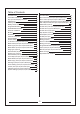
Included Items Please check the parts and accessories in the package. In the event of defective or missing parts, please contact the retailer for help. 1 2 3 1. AH6T 2.4G 6-Channel Transmitter 2. Hex key 3.
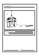
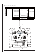
Transmitter Identification 1 Antenna 2 Signal Light 3 8 Knob 4 Swtich E 5 Swtich H Swtich G 7 Swtich F 13 Right Rubber Panels Mode 2 Elevator / Aileron Stick 14 Display Screen Mode 3 Throttle / Rudde Stick 15 Left Rubber Panels Mode 4 Elevator / Rudde Stick 9 6 Mode 1 Throttle / Aileron Stick 10 Mode 1 Elevator / Rudder Stick 21 Mode 2 Throttle / Rudder Stick Mode 3 Elevator / Aileron Stick Mode 4 Throttle / Aileron Stick 16 Back Button Mode 1/Mode 3 Throttle Trim 17 Speaker 22
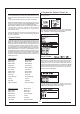
Key Input and Display Funcitons The AH6T utilizes a roller that can be rotated or pressed and two buttons, Back and Clear that are used to access and program all functions. Battery Alarm and Display When the transmitter voltage drops below 4.3 volts, "Warning Low Battery" will flash and an alarm sound. If you are flying when this occurs, land immediately. Programmable Alarms Rotate the ROLLER to adjust values or to select options Press the ROLLER to access screens or functions.
Receiver Installation SmartSafe In gas and glow aircraft install the main receiver by wrapping it in protective foam and fastening it in place using rubber bands or hook and loop strap. In electric airplanes or helicopters, you can use thick double-sided foam tape to fasten the main receiver in place. Mount the remote in a slightly different location from the primary receiver. This gives tremendous improvements in path diversity.
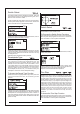
To Access the System Setup List Press Power Switch to turn on the transmitter and enter the main screen. 3. LED lights will continue to blink. 4. Move transmitter’s control sticks and switches to the desired Preset Failsafe positions then turn it on in bind mode. 5. The system should connect in less than 15 seconds. NOTICE: Failsafe features vary according to receiver, so if using a receiver other than the AH6R AH6RS, consult your receiver’s instructions for the failsafes that apply.
Model Type Model Type programs the selected model memory to f u n c t i o n i n H e l i c o p t e r, A i r p l a n e o r M u l t i c o p t e r programming. You should program Model Type first when setting up a new model. Note: You can assign each model memory its own model type. To Access the Model Type Function Press and hold the roller while turning on the transmitter. When System Setup appears on the screen, release the roller. The AH6T is now in System Setup Mode.
Switch Select The Switch Select function allows the switches, knob and right and left trimmers to be assigned to the gear, Aux1, Aux2 or Aux3 channels or inhibit. Press and hold the roller while turning on the transmitter. When System Setup appears on the screen, release the roller. The AH6T is now in System Setup Mode. Switch Select The Switch Select function allows the switch, knob, right and left trimmers, hold, throttle curve.
Note: You will need to re-bind after moving models Highlight the desired Trim value then press the roller to access. Rotate the roller to change to the desired trim value. Press to accept. Repeat to adjust all trim steps. Model Reset Model Reset is typically used to clear the programming for a model you will no longer be flying. Model Reset resets the programming for the selected model to factory defaults. No other model memories will be affected.
Warnings The Warnings function programs an alarm to sound if specific switches or stick positions are in an unsafe position when the transmitter is first turned on. In helicopter model type default warnings include Throttle, Stunt 1, Stunt 2 and Hold. In airplane model type these warnings include Throttle Low, Flaps, Gear, Flight Mode 1 and Flight Mode 2.
System Settings Use the System Setting screen to establish the overall transmitter setting that will apply to ALL model memories. When using Wireless Master, Rotate the roller to Bind then press. The following screen appears: To Access the System Settings Function Press and hold the roller while turning on the transmitter. When System Setup appears on the screen, release the roller. The AH6T is now in System Setup Mode. Highlight System Settings then press.
Servo Reverse To Access the Inactive Warning Time Setting To Access the Reverse Function Rotate the roller to access the inactive warning time setting then press and set the parameter. Rotate the roller to highlight Servo.Reverse then press. The following screen appears: Function Mode The AH6T organizes the programming screens in two separate categories: System Setup Mode and Functions Mode. Function Mode programming adjusts a model’s flight characteristics at the field. Airplane Model Servo.
Servo.Travel Rotate the roller to the channel you need to setup then press after that rotate the roller to adjust the parameter. To Access the Servo.Travel Rotate the roller to highlight Servo.Travel then press. The following screen appears: D/R & Exponential Dual Rates and exponentials are available on the aileron, elevator and rudder channels. You can assign them to numerous switches including the flight mode switch.
To Select Switch Rotate the roller to highlight Sw (switch) then press to access the switch options. Select the desired switch to change the dual rate for that channel or inhibit then press the roller to make it active. Note: You can assign multiple channels to a single switch to affect the dual and exponential rates of all.
Throttle Cut Throttle Curve The Throttle Cut function allows you to shut off an engine with the Trainer switch, Gear switch or the Right or Left trimmer. When you activate the programmed switch, the throttle channel is driven to it’s preprogrammed value normally off. This effectively kills the engine. Release the programmed throttle cut switch/trimmer, and normal throttle operation resumes. The Throttle Curve function allows throttle output vs. input positions to be adjusted.
Rotate the roller to highlight Throttle Curve then press to access that screen. Flap System Selecting a Flight Mode The AH6T flap system offers up to three programmable flap and elevator positions (normal, mid and land). You c a n a s s i g n t h e m t o a v a r i e t y o f s w i t c h e s . Yo u c a n program a Speed function to slow flap and elevator compensation travel for a scale effect.
Rotate the roller to highlight Swashplate then press to access. Repeat this for all desired Flap and elevator positions (Normal, mid and land). To adjust a Swashplate Value Adjusting the Flap Speed Rotate the roller to select Speed then press. Now rotate the roller to adjust the flap speed. Press the roller to accept. The flap speed affects the flap and elevator compensation. The flap and elevator will reach their flap positions at the same time.
Adjusting the Rate Values Rotate the roller to the parameter you need to setup then p r e s s . A d j u s t t h e p a r a m e t e r, R e p a r t t h i s t o s e t a l l parameter. Adjusting the Curve Move the flight mode switch in the position you wish to adjust. Rotate the roller to highlight one of the five available pitch curve values (Low, 25%, 50%,75%, High). Press to access that value. Pitch Curve The AH6T features a 5-point Pitch curve. You can set up to four separate Pitch curves.
Mixing Aileron to Rudder Mix The Ah6T offers eight mixes in airplane model type. There is an Elevator to Flap mix, Aileron to Rudder mix, and six user-programmable mixes that allow the mixing of any channel to any other channel. Programmable mixes include a trim offset function that adjusts the mix crossover point and a trim include function that applies the master’s trim to the slave channel.
Mixing Programmable mixes allow any channel to be mixed to any other channel or to itself. Popular programmable mixes include rudder to steerable nose wheel, dual rudder mix, dual elevator mix, rudder to aileron and rudder to elevator mix for knife edge correction. To Access Programmable Mixes (1 thru 6) With the Elevator to Flap mix screen displayed, rotate the roller to highlight Ele > Flp then press the roller. Now rotate the roller to select programmable Mix, 1, 2, 3, 4, 5, or 6 and press the roller.
Swashplate Mix The Swashplate Mix typically corrects swashplate timing issues by mixing Aileron to Elevator and Elevator to Aileron. When adjusted correctly, the Swashplate causes the helicopter to roll and pitch accurately with minimal inter-reaction. To access Swashplate Mix With the C Mix screen displayed, rotate the roller to highlight Cyclic > Thro then press. Select Swashplate a n d p r e s s t h e r o l l e r. T h e S w a s h p l a t e M i x s c r e e n appears.
include activated, the master channel’s trim affects the slave channel’s trim as well. Rotate the roller to the switch you need to ues then press,after that select the relevant switch. Activating Trim Include Rotate Roller to highlight Trim then press to select INH or ACT. Timer Program AUX AUX0 , 1 can customize the output of 10 different states. Notice : Priority output low position. To access the Program AUX Function Rotate the roller to highlight Program AUX then press.
To Program a Time Rotate the roller to highlight Time then press to access. You can highlight the seconds or minutes. Press the roller to access minutes or second. Rotate the roller to select the desired Stick value then press the roller to accept the displayed value. Rotate the roller to select the desired time. Press to accept. There are a couple of ways to reset the internal timer.
Mode Changes The AH6T can be easily converted to mode 1, 2, 3, or 4. This conversion requires a mechanical and a programming change. (Stick and switch positions for mode 1 and 2 are illustrated on pages 8 and 9.) Following are detailed instructions on making mode changes. Mechanical Conversion Mechanical conversion is required to switch between modes 1 and 2 or between modes 3 and 4.
Programming Conversion When making a mode conversion, the programming must also be changed and when changing throttle elevator positions the transmitter must be recalibrated in the systems setting screen. To Access the System Settings Function Highlight System Settings then press the roller to access the System Settings function. The System Settings screen will appear. When changing modes that swap throttle and elevator positions it’s necessary to recalibrate the sticks.
FCC Statement: This equipment has been tested and found to comply with the limits for a Class B digital device, pursuant to part 15 of the FCC Rules. These limits are designed to provide reasonable protection against harmful interference in a residential installation. This equipment generates, uses and can radiate radio frequency energy and, if not installed and used in accordance with the instructions, may cause harmful interference to radio communications.
前言 感谢您选择GWY的产品。为了让您能够更好的了解和使用这台AH6T发射机,我们衷心的希望您认真地阅 读完这本说明书之后再进行相关操作,并请妥善保管以备后用。 如需了解更多资讯,请访问官方网址:www.zondahobby.com / www.zondahobby.com.cn 重要声明 遥控模型不是玩具!为避免危险事故的发生,请勿随意操作遥控模型,模型商品必须在当地政府允许和 规定的情况或条件下使用。消费者自购买当日起即承担该模型使用的一切风险,产品售出后GWY将不负任何 操作和使用控制上的任何性能与安全责任。也无法对消费者零件使用的损耗异常或组装不当所发生的意外负 任何责任.
目录 检查包装物及配件 发射机各部位介绍介绍 按键与屏幕功能 数位微调 无动作警示 电池警示及屏幕 编程警示 AH6R/AH6RS接收机 安装接收机 对码操作 安全保护 保留最后指令安全保护 预设安全保护 系统设定 进入系统设定菜单 机种模式选择(直升机、飞机、多旋翼) 机种型式(直升机、飞机、多旋翼) 模型名称(直升机、飞机、多旋翼) 机翼型式选择(飞机) 开关选择(飞机) 倾斜盘模式(直升机) 开关选择(直升机、多旋翼) 微调设置(直升机、飞机、多旋翼) 模式重设(直升机、飞机、多旋翼) 复制模式(直升机、飞机、多旋翼) 警告(直升机、飞机、多旋翼) 功率设定(直升机、飞机、多旋翼) 可编程教练(直升机、飞机、多旋翼) 信号丢失保护(直升机、飞机、多旋翼) 系统设定(直升机、飞机、多旋翼) 4 5 6 6 6 6 6 6 7 7 7 7 7 8 8 8 9 9 9 10 10 10 10 11 11 12 12 12 13 13 功能模式 正反舵(直升机、飞机、多旋翼) 行程调整(直升机、飞机、多旋翼) 速度&辅助微调(直升机、飞机、多旋翼) 双重比率和感度指数(直升机、飞机、多旋翼) 副翼差动(飞机
检查包装物及配件 打开包装盒后,请先检查整机与附送配件是否齐全,若有遗漏,请向所销售单位反映,索取。 1 2 3 1. AH6T 2.4G六通道发射机 2. L型螺丝扳手 3.
发射机各部位介绍 1 天线 Mode 1 油门及副翼摇杆 13 右橡胶握手 2 指示灯 Mode 2 升降及副翼摇杆 14 LCD显示屏 3 旋钮 4 开关 E 5 开关 H 6 开关 G 7 开关 F 8 Mode 1 升降及方向摇杆 21 Mode 3 油门及方向摇杆 15 左橡胶握手 Mode 4 升降及方向摇杆 10 Mode 3 升降及副翼摇杆 Mode 4 油门及副翼摇杆 16 返回按钮 9 Mode 2 油门及方向摇杆 Mode 1/Mode 3油门微调 17 蜂鸣器 22 开关 C Mode 2/Mode 4升降微调 18 清除按钮 23 开关 B Mode 1/Mode 2副翼微调 19 Mode 3/Mode 4方向微调 Mode 1/Mode 2方向微调 24 开关 A Mode 3/Mode 4副翼微调 25 开关 D 26 对码按钮/开关 I 20 Mode 1/Mode 3升降微调 11 电源开关 Mode 2/Mode 4油门微调 12 滚轮 1 3 26 24 2 25 23 4
按键与屏幕功能 AH6T的滚轮功能可以选取列表。另外,清除键和返 回键可以用来操作所有功能。 Flash data be damaged reboot automatically repair 电池警示及屏幕 当遥控器电压低于4.3伏特时,"低电量警示"就会闪烁, 并发出警示音。若操控飞机时有上述情形发生,请立 即降落。 转动滚轮,就可以使用屏幕上的功能。将滚轮按住, 调整设定值或是选取选项。 按下返回键,可以返回前一个画面。 按下清除键,就会将选择的设定值回复到默认值。 数位微调 AH6T 2.
安装接收机 安全保护 使用汽油与甲醇发动机飞机时,用保护泡棉把主接 收机包好,并用橡皮筋,或钩子、吊条将之固定住。 使用电动飞机或直升机,您可用厚双面泡棉胶带固 定接收机。注意,飞机有很多材质容易导电(例如: 较大型汽油发动机, 碳纤维, 导管等),讯号可能会 减弱。 注意:接收机天线尽可能的远离电源线,最理想的 是天线相互垂直。 SmartSafe安全保护在保留最后指令安全保护与默认 安全保护中执行。SmartSafe是油门通道的特色,提 供下列好处: 防止只有接收机开机时,电动马达突然启动(无讯号)。 防止变速器启动。直到链接后,才变成低油门位置。 当讯号消失时,可以关闭电动马达及让汽油/甲醇发 动机怠速。 油门低于标准,变速器不会启动。 若飞行时,失去连结: -在接收机固定时,SmartSafe设定油门为正确位置。 接收机电源需求 当系统完全负载时,机载电源系统提供无中断的足够 电力是重要的(舵机最大的飞行负荷)。不足的电源系 统是造成肇事的主因。一些电源系统零件会影响适机 载传输足够电力,包含:挑选的接收机电池组(一些电 池、电容、电池种类、充电状况)、开关线束、电池 引线(如果有使
进入系统设定菜单 3.LED灯会持续闪烁。 4.将遥控器的摇杆及按键设为理想的默认安全回复位 置,并将之调成固定模式。 5.系统链接时间应少于15秒。 注意:任何接收机有所不同,安全回复也不大一样, 若使用AH6R或AH6RS以外的接收机,请参照接收机 手册。 飞行前,随时确认接收机固定是否正确以及安全回 复是否设定。您可以确认您的系统是否链接,关掉 遥控器。确认是否为低油门位置。 特别注意: 请确认您的飞机是在地上。若安全回复没 有设定,飞机的油门位置可能会变成中段或全满。 按一下发射机电源开关,打开发射机,进入发射机主 界面。 1:HELI T1: T2: 0:00 0:00 5.
机种型式 机种型式是用来选择直升机、飞机及多旋翼的编程。 首次设定新模型时可以选择机种型式。注意:您可以 分配机种型式给每个内存。 进入机种型式 进入系统设计模式菜单后,选择机种型式菜单,并 按下滚轮,进入该选项: 选择此项后,会出现以下界面,滚动滚轮,选择欲选 的字,按下滚轮选取。重复上述步骤,以命名名称。 您在主画面会看到设好的名称。按下清除键就可以删 除目前名称的字。 机翼型式选择 选择此项后,会出现以下界面,滚动滚轮,选择所需 的机种型式(直升机、飞机或多旋翼),并按下滚轮, 选取模型。 使用机翼型式选择,您可以调整飞机的机翼及尾翼混 控。共有四种机翼型式(标准、双副翼、升降舵、双 襟翼、)以及两种尾翼型式(标准、V尾翼、)。在设定 其他机翼或尾翼相关编程(襟翼、行程调整、辅助微 调等)前,您必须选择飞机的正确机翼及尾翼型式。 进入机翼型式选择 进入系统设计模式菜单后,选择机翼型式菜单,并 按下滚轮,进入该选项: 选择YES选项,并按下滚轮选取此机种模式。选取 NO,则会返回之前的画面。 注意:当您切换机种模式时(直升机转飞机或飞机转直 升机),目前选取的模式内存会重设,变为默认值。 所有先
开关选择 开关选择用于分配开关、旋钮,以及左右微调杆给起 落架、油门保持、油门曲线。 编程开关选择 进入系统设计模式菜单后,选择开关选择菜单,并 按下滚轮,进入该选项: 开关选择 开关选择用于分配开关、旋钮,以及左右微调杆给起 落架、油门保持、油门曲线。 编程开关选择 滚动滚轮,选择所需的开关、旋钮或微调杆,并按下 滚轮进入选项: 进入系统设计模式菜单后,选择开关选择菜单,并 按下滚轮,进入该选项: 滚动滚轮选择您希望使用的开关、旋钮或微调杆信道 或功能,按下滚轮选取。信道或功能只能分配一次。 重复上述动作,选取全部欲选的开关位置。 滚动滚轮,选择欲选开关、旋钮,或是微调杆,并按 下滚轮。 倾斜盘模式 使用倾斜盘型式,您可以调整直升机的倾斜盘混控。 共有六种倾斜盘型式(标准、3-servo 120 CCPM、 3-servo 140 CCPM、3-servo 90 CCPM、3-servo 135 CCPM,以及2-servo 180 CCPM)。在设定其他 倾斜盘编程(螺距曲线、行程调整、辅助微调等)前, 您得选择直升机的正确倾斜盘型式。 进入倾斜盘模式 进入系统设计模式菜单后,选择倾斜盘模式菜
复制模式 滚动滚轮,选择微调设置,并按下滚轮,就会出现该 选项。会出现下面画面: 复制模式用于目前选择的模式编程。有二十个模式内存 可用。一些常用的复制模式功能包含: 可以移动内存的模式次序,按照种类及型式整理等。 附注:移动模式后,您须要重新固定装置。 飞机编程时,可以复制原先的设定。附注:若您想要以 同样的模式另外复制两个模式,您必须重新固定装置。 复制目前的模式编程至相似的新模式。许多玩家认为 这是个好方法,可以准确编程新模式。比方说, Vibe 50 w/120CCPM混控、陀螺仪和调速器编程,可以提 供不错的编程给其他甲醇动力的120CCPM混控直升机。 注:要被复制的模式会被取代,目前的编程会被永久删除。 进入复制模式 选择欲选的微调值,并按下滚轮,选择设定值。滚动 滚轮,变更微调值。按下滚轮,并选取设定好的值。 重复上述动作,调整所有微调幅度。 进入系统设计模式菜单后,选择复制模式菜单,并按下 滚轮,进入该选项: 模式重设 模式重设一般用于清除不再使用的模式编程。这可以 重新设定选择的模式,调回默认值。并不会影响其他 模式内存。若重设模式,则该模式的编程就会永久删 除且不能恢复。
警告 警告功能用于警示遥控器开机时特定开关或摇杆位置 不正确或安全。直升机模式中,默认的警告包含:油 门、特技1、特技2,和油门固定。飞机模式中,警告 则包含:低油门位置、襟翼、起落架、飞行模式和飞 行模式2。若遥控器开机时,任何开关或摇杆没有在 低位置,警告音就会响起;屏幕会出现警告,也不会 有讯号传送。等到摇杆或开关回到正确位置,警告才 会解除。 进入Mode可设置发射机工作模式: 进入警告 进入系统设计模式菜单后,选择警告菜单,并按下滚 轮,进入该选项: 进入Region可设置发射机工作区域: 就会出现该选项。会出现下面画面: 可编程教练 进入系统设计模式菜单后,选择可编程教练菜单,并 按下滚轮,进入该选项: 选择欲选的警告(飞机模式下可选用:油门、特技1、 特技2,或油门固定、油门、襟翼、起落架、飞行模 式1和飞行模式2),并按下滚轮选择。现在滚动滚轮, 关闭或启动选择的警告。将遥控器关机,以确认警 滚动滚轮,选择相应模式并按下,会出现下面界面: 告是否运作,并将选择的开关或油门杆调到不正确的 Inhibit:禁用 Line Master:有线教练模式 位置,再打开遥控器。警告音会响;屏幕会
系统设定 在无线教练模式下,第一次使用,应滚动滚轮致Bind 进行对码,如下图: 进入系统设定的画面,可以改变整个遥控器设定,套 用于任何模式内存。 系统设定 进入系统设计模式菜单后,选择系统设定菜单,并按 下滚轮,进入该选项: 此时学员机需要开机进行对码: Binding......
正反舵 进入闲时报警时间设置 在系统设定画面中,滚动滚轮,选择闲时报警时间设置, 并按下滚轮,可设置闲时报警时间。 进入正反舵 进入功能模式菜单后,选择正反舵菜单,并按下滚轮, 进入该选项: 功能模式 AH6T的编程有两种分类:系统设定和功能模式。功能 模式用于调整模型的飞行型式。 飞机功能模式 Servo. Reverse Servo. Travel Servo. Speed&trim D/R and Expo Differential Throttle Cut Throttle Curve Flap System Mixing Timer Monitor 直升机功能模式 Servo. Reverse Servo. Travel Servo. Speed&trim D/R and Expo Throttle Cut Throttle Curve Swashplate Gyro Pitch Curve Mixing Timer Monitor 多旋翼功能模式 Servo. Reverse Servo. Travel Servo.
行程调整 进入行程调整 进入功能模式菜单后,选择行程调整菜单,并按下滚 轮,进入该选项: 就会出现该选项,会出现下面画面: 选择您想要的通道,按下滚轮,就可以滚动滚轮调整 其数据,确认后再次按下滚轮键即可。 双重比率和感度指数 双重比率和感度指数可用于副翼、升降舵和方向舵通 道。您可以指定它们到许多开关,包含飞行模式开关。 双重比率 选择您想要的通道,按下滚轮,就可以滚动滚轮调整 其数据,确认后再次按下滚轮键即可。 速度&辅助微调 进入速度&辅助微调 进入功能模式菜单后,选择速度&辅助微调菜单,并 按下滚轮,进入该选项: 会影响整体限位,也会影响整体控制反应敏感度。减 少双重比率,就可以降低最大控制限位,也会降低整 体敏感度。 感度指数 会影响围绕机体中枢的灵敏度,而不影响整体控制灵 敏度。感度指数正值会降低机体中枢的控制灵敏度, 以准确地调整控制感度,而不会影响最大控制反应。 注意:感度指数正值和负值都可使用。感度指数正值 会降低机体中枢的敏感度。这并不会影响最大控制权 限,建议使用感度指数正值。感度指数负值会增加机 体中枢灵敏度,通常不会用到。 进入双重比率和感度指数 进入功能模式菜单后
负值。然而,通常副翼的上行程比下行程,还要重要。 注意:只有双襟副翼或升降舵辅助翼启动时才有用,每 个副翼舵机都要有各自的通道。 进入开关选择 滚动滚轮,选择开关,按下滚轮,进入开关选项。选 择您想要的调整双重比率的开关,按下滚轮,启动该 功能。 注意:您可以指定多个通道给单一开关,调整双重比 率和感度指数。 进入差速器 进入功能模式菜单后,选择差速器菜单,并按下滚 轮,进入该选项: 进入选择调整开关位置 差速器的默认值为关闭。按下滚轮,选择Inhibit,并选 择下列开关位置: 注意位置:画面中央的位置数值为0。移动画面下方的 开关位置,范围从0、1到2。当您调整双重比率或感 度指数时,数值会被选定。当开关在所在位置(0、1 或2)时,就会自动启用数值。.
关闭油门 油门曲线 您可以用教练按钮、起落架开关或左右微调杆关闭发 动机。若您启动已编程的开关,油门通道就会切换到 编程的设定值,通常显示关闭。发动机就会被关掉。 放开以编程的关闭油门开关/微调杆,油门就会重新 启动。 油门曲线可用于调整油门输出与输入的位置。通常在 飞机盘旋或滚翻飞行时,油门曲线可用于提高油门反 应,或调整油门反应敏感度。用编程开关,您可将油 门曲线设定为单一曲线(调成)开启,或是设定为三个 曲线。在画面左边有个五点油门曲线图,可以用来调 整油门曲线数值。Expo功能可用来消除油门曲线。 启动关闭油门,并分配到开关或微调杆 进入功能模式菜单后,选择关闭油门菜单,并按下滚 轮,进入该选项: 滚动滚轮,选择关闭油门,并按下滚轮后,就会进 入关闭油门画面。 选择关闭,并按下滚轮,进入开关选项。滚动滚轮, 选择想要关闭油门的开关 (教练、起落架、混控、 左微调或右微调),按下滚轮,为开关编程。 进入油门曲线 进入功能模式菜单后,选择油门曲线菜单,并按下滚 轮,进入该选项: 滚动滚轮,选择油门曲线,并按下滚轮后,就会进 入油门曲线画面。 滚动滚轮,选择五个曲线数值选项(低、25%,、
滚动滚轮,选择油门曲线,并按下滚轮后,就会进 入油门曲线画面。 襟翼系统 AH6T的襟翼系统有三个可编程襟翼和升降舵位置(标 准、中央、降落)。您可以分配不同的开关操作。您 可以使用速度功能,减缓襟翼和升降舵补整。襟翼系 统画面左边的图表显示舵机位置,可用来设定和调整 襟翼。 注意:襟翼系统只能使用于机翼型式为襟翼。 选择飞行模式 选择画面中您想要的飞行模式,并按下滚轮,选择。 被选择的飞行模式会变暗,显示您的选择。 N= 标准 / 1= 特技1 / 2= 特技 2 / H= 固定油门 调整油门曲线 进入襟翼系统 进入功能模式菜单后,选择襟翼系统菜单,并按下滚 轮,进入该选项: 滚动滚轮,选择襟翼系统,并按下滚轮后,就会进 入襟翼系统画面。 移动飞行模式开关到您想要调整的位置。滚动滚轮, 选择五个曲线数值选项(低、25%,、50%、75%, 以及高),择一选择。按下滚轮,选取数值。 选择开关 滚动滚轮,调整选择的输出数值。注意左边曲线图上 的位置。重复步骤,调整所有数值。 启动Expo功能 滚动滚轮,选择EXPO,并按下滚轮,进入油门曲线 Expo功能。选择Inh或Act,关闭或启动Expo功
重复步骤,调整所有襟翼和升降舵位置(标准、中央, 以及降落)。 调整襟翼速度 调整倾斜盘数值 滚动滚轮,调整倾斜盘数值,注意数值有正值及负值。 按下滚轮,确认数值。 滚动滚轮,选择速度,并按下滚轮。滚动滚轮,调整 襟翼速度。按下滚轮,以确认选择。襟翼速度会影响 襟翼和升降舵补整。同时,襟翼和升降舵会调整位置。 陀螺仪 陀螺仪功能可以编程和调整陀螺仪增益。 倾斜盘 进入陀螺仪功能 在倾斜盘画面中,启动CCPM混控时,您可以调整副 翼、升降舵,以及螺距的行程。倾斜盘数值会提高或 降低已选择通道的整体控制行程。比方说,若您提高 螺距数值,三个控制螺距的舵机运作就会提高。若您 提高副翼数值,副翼和螺距舵机运作也会提高。提高 或降低数值,会影响功能行程,而不只是影响个别舵 机而已。注意:倾斜盘数值有正值及负值。要达到正确 的副翼、升降舵和螺距行程,要先使用正反舵功能, 设定舵机的副翼、升降舵和螺距通道方向。当副翼输 入摇杆偏向倾斜盘左和右,方向舵输入摇杆偏向倾斜 盘前和后时,您可以使用上述方法。您可以用这个功 能,同步输出。就可以调整倾斜盘正值与负值,让副 翼、升降舵和螺距的行程方向正确。 进入功能模式
调整螺距曲线 调整幅度数值 滚动滚轮,选择想要的数值,并按下滚轮。选择数值。 移动飞行模式开关到您想要调整的位置。滚动滚轮, 重复步骤,设定所有数值。 选择五个曲线数值选项(低、25%,、50%、75%,以 及高),择一选择。按下滚轮,选取数值。 螺距曲线 AH6T有五点螺距曲线。您可以设定4个个别的螺距曲 线。画面左边的图表,可以辅助调整螺距曲线。 Expo功能可用于消除螺距曲线。 滚动滚轮,调整选择的输出位置数值。注意左边曲线 图上的位置。 进入螺距曲线功能 进入功能模式菜单后,选择螺距曲线功能菜单,并按 下滚轮,进入该选项: 重复步骤,完成所有调整。 启动Expo功能 滚动滚轮,选择EXPO,并按下滚轮,进入Expo功能。 选择Inh或Act,关闭或启动Expo功能,并按下滚轮, 确认关闭或启用该功能。 滚动滚轮,选择螺距曲线功能,并按下滚轮后,就会 进入螺距曲线功能画面。 选择飞行模式 选择画面中您想要的飞行模式,并按下滚轮,选择。 被选择的飞行模式会变暗,显示您的选择。 N= 标准 / 1= 特技1 / 2= 特技2 / H= 固定油门 20
混控 副翼-方向舵混控 AH6T有八个飞机混控。包含升降舵-襟翼混控、副翼方向舵混控,以及六个使用者编程混控,可以混控通 道。可编程混控包含,一个调整补差微调,以及一个 具有教练-学生通道的微调。 使用副翼-方向舵混控可以解决J3 Cub飞机的逆偏航, 并更容易做出翻转。 进入混控功能 进入功能模式菜单后,选择混控功能菜单,并按下滚 轮,进入该选项: 滚动滚轮,选择混控,并按下滚轮。注意若选择适当 的机翼型式,升降舵-襟翼混控会出现在画面。 进入副翼-方向舵混控 若您进入系统设定的机翼型式,选择襟翼选项,方向 舵-襟翼混控会出现。滚动滚轮,选择ELE > FLP,并 按下滚轮。滚动滚轮,选择Ail > RUD,并按下滚轮。 就会出现副翼-方向舵混控的画面。 指定副翼-方向舵混控开关 滚动滚轮,选择Sw:在画面的最下方。按下滚轮,进入 开关选择功能,再按下滚轮,选择想要的开关,开启/ 关闭副翼-方向舵混控.
混控 可编程混控可用于通道相互混控或本身各自混控。 普遍的可编程混控包含,方向舵-可操作前轮、双方 向舵混控、双升降舵混控、方向舵-副翼混控和方向 舵-升降舵混控。 AH6T有八个直升机混控。当有副翼、升降舵和/或方 向舵输入时,您可以编程倾斜盘-油门混控。当倾斜盘 和方向舵输入时,这可防止转速减少。 混合副翼-升降舵混控和升降舵-副翼混控,以调整倾 斜盘时程。有六个可编程混控,可混控通道。包含起 进入可编程混控(1到6) 升降舵-襟翼混控显示在画面中,滚动滚轮,选择Ele 落架开关在内,您可以在多个飞行模式中,操作混控。 > Flp,并按下滚轮。滚动滚轮,选择可编程混控1、 可编程混控包含微调offset功能,可用来调整混控交错。 而微调内含功能则可用于教练微调与学生通道链接。 2、3、4、5或6,并按下滚轮。混控画面会出现。 进入混控功能 进入功能模式菜单后,选择混控功能菜单,并按下滚 轮,进入该选项: Offset功能 当两个混控聚合时,就可以使用Offset功能。通常这 个数值是0%。若需要调整补差,可以使用下列方法: 滚动滚轮,选择Offset,并按下滚轮,选择Offset幅 度。滚动滚轮,调
倾斜盘混控 混合副翼-升降舵混控和升降舵-副翼混控,以调整倾 斜盘时程。当正确调整时,倾斜盘会让准确俯仰翻转 ,相互效应达到最小。 进入倾斜盘混控 倾斜盘混控画面出现时,滚动滚轮,选择Cyclic > Thro, 开关选择 并按下滚轮。选择选转盘,并按下滚轮。倾斜盘画面 滚动滚轮,选择“SW”项,选择所需开关和开关位置。 会出现。 调整倾斜盘幅度 滚动滚轮,选择想要的幅度,并按下滚轮。滚动滚轮, 调整数值。数值有正值+和负值-,与油门混控的方向 相反。调整所以想要通道的数值。 调整可编程混控幅度 滚动滚轮,选择想要的幅度,并按下滚轮。滚动滚轮, 调整数值。您可用正值或负值,使学生通道方向相反。 调整两个方向/数值的幅度。 确认可编程混控运作正常,以及方向正确。打开飞行 模式开关。 移动可编程教练通道时,观察学生通道。学生信道应 跟随教练通道移动。 可编程混控 可编程混控可用于通道相互混控或本身各自混控。 进入可编程混控(1到6) 遥控盘混控画面出现时,滚动转轴,选择Cyclic > Thro,按下滚轮选择可编程混控,1、2、3、4、5, 或6,再按下滚轮。会出现混控画面。 Offset功能 当两个混
舵机等)时,就会使用微调内含功能。微调内含功能启 动时,教练通道微调会影响学生通道微调。 滚动滚轮,选择需要控制的开关处,并按下滚轮,选 择相应的开关和位置。 启动微调内含功能 滚动滚轮,选择微调。按下滚轮,选择INH或ACT。 定时器 可编程辅助通道 辅助通道0、1可以自定义输出10个不同的状态。 注意:输出结果低位置的优先输出。 进入可编程辅助通道 进入功能模式菜单后,选择可编程辅助通道菜单,并 按下滚轮,进入该选项: AH6T拥有两组定时器功能,在主画面中可以使用倒数 计时或定时。当计时的时间一到,就会有警示响起。 您可以用教练按钮、左或右微调杆来启动定时器,或 是油门提高,超过设定范围时,自动启动定时器。此外, 在主画面中,透过内部定时器,您可以看到模型的操 作时间。 进入定时器画面 进入功能模式菜单后,选择定时器功能菜单,并按下 滚轮,进入该选项: 滚动滚轮,选择需要设置的通道,并按下滚轮。 滚动滚轮,选择定时器功能,并按下滚轮后,就会进 入定时器功能画面。 Timer-1 滚动滚轮,选择需要设置的位置,并按下滚轮。 滚动滚轮,选择需要设定的值位置,并按下滚轮,转 动进行设定。
编程时间 Timer-1 滚动滚轮,选择时间,并按下滚轮,进入选项。您可 以选择分钟或秒钟。按下滚轮,确认选择分钟或秒钟。 Timer-1 滚动滚轮,选择想要的摇杆数值,并按下滚轮,确认数值。 重设内部定时器 您可用一些方法重设内部定时器。滚动滚轮,选择内部 定时器:重设,按下滚轮,重新设定定时器为0:00:00 滚动滚轮,选择想要的时间。按下滚轮,确定选择。 编程音调、震动、音调/震动或关闭 Timer-1 滚动滚轮,选择音调,并按下滚轮,确认选择。您可 以选择关闭、音调、震动或音调/震动。 sA Timer-1 您可以按下清除键,重新设定倒数定时器或定时器。 监控 选择定时器启动模式 滚动滚轮,选择启动,并按下滚轮,进入选项。共有 五种启动模式:教练开关、油门、油门1定时器、左或 右微调杆。 油门1定时器- 当油门位置超过标准时,定时器会启 动。不管油门位置,定时器会持续运作。 油门 - 当油门位置超过标准时,定时器会启动。若 您将油门低于编程位置,定时器就会暂停,当油门高 过编程位置时,定时器就会恢复运作。这对操作电子 发动机飞机的玩家来说很有用,马达运作时间才是最 重要的。 监
更换模式 AH6T可以切换模式,从1、2、3到4。这种切换有机械功能及程序的改变(前面有介绍模式1和2、模式3和4的摇 杆和开关图示。)具体操作方法如下: 机械功能切换 机械功能切换需要变更模式1及模式2或模式3及模式4的开关。方向舵中心弹簧及油门压片要装在适当的阻尼条 上,油门杆必须切换。 1. 将发射机后扶手的橡胶握手拉开和两个橡胶塞,出现A、B、C、D、E、F螺丝孔(如下图发射机背面图所示) 发射机背面图 D C E B F A MODE 1 MODE 2 油门摇杆 MODE 3 副翼摇杆 方向摇杆 MODE 4 方向摇杆 2. 左手换右手 1)用十字螺丝批将A调节螺丝拧松,调至摇杆上下移动无阻力状态即可。 2)用十字螺丝批将B调节螺丝锁紧,调至摇杆上下移动后可自动反弹状态即可。 3)用十字螺丝批将C调节螺丝拧松,调至摇杆上下移动无反弹状态即可。 4)用十字螺丝批将D调节螺丝锁紧,调至摇杆上下移动有阻力状态即可。 3.
程序功能切换 切换模式时,您也必须改变编程,另外,改变油门和升降舵位置时,要在遥控器系统设定中重新设定。 进入系统设定 进入系统设计模式菜单后,选择系统设定菜单,并 按下滚轮,进入该选项: 按下滚轮后就会出现以下菜单 滚动滚轮,选择想要的模式,按下滚轮,进入模式。 切换模式时,改变油门和升降舵位置,重新设定摇杆, 这很重要。若编程模式切换,下次开机时,设定画面 会自动出现。如下图: 此时请大幅度移动摇杆几圈,并调回中央(包含油门摇 杆及发射机旋钮键)。若所有摇杆都调回中央,当出现 以下界面时,按下储存,完成设定。 调整摇杆松紧度 AH6T有调整油门、副翼、升降舵和方向舵松紧度功能。橡胶栓在机壳后面,您可轻松找到摇杆螺丝,调整松 紧度,而无需取下整个外壳。 调整摇杆松紧度 1.取下两个橡胶塞,并取下握把。您可以找到油门、副翼、升降舵和方向舵螺丝。 MODE 2 调节升降 螺丝 调节副翼 螺丝 调节方向 螺丝 2.使用十字螺丝批,调整螺丝松紧度。顺时针锁紧螺丝,逆时针则可松开螺丝。 3.
Global Distribution Office: Zonda Hobby Technologies Electronic Limited Room 1, 1/F, Kam Hon Industrial Building, No.8 Wang Kwun Road, Kowloon Bay, Kowloon, Hong Kong Tel: (852) 3160 8886 Fax: (852) 3160 8884 Official Website: www.zondahobby.com / www.zondahobby.com.