Table of Contents CHAPTER 1 INTRODUCTION ................................................................ 2 1.1 PACKAGE CONTENTS ................................................................................................. 2 1.2 KNOW YOUR ZVC7610W .......................................................................................... 3 1.3 FEATURES AND BENEFITS........................................................................................... 4 1.4 SYSTEM REQUIREMENTS ........................
Chapter 1 Introduction Thank you for purchasing the Zonet ZVC7610W, a powerful and high-quality image wireless IP camera. ZVC7610W can be installed as a standalone system within your application environment easily and quickly, and supports remote management function so that you can access and control it using a Web browser on your PC. 1.1 Package Contents Check the items contained in the package carefully before installation. One ZVC7610W One AC Power Adapter One Wireless Antenna.
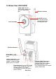
1.2 Know Your ZVC7610W Power LED indicates ZVC7610W is power ON with the steady amber light. Wireless Antenna Link LED indicates ZVC7610W network connectivity with the flashing green light. Lens Assembly Front View Wireless Antenna Screw Hole is used to connect the camera stand.
1.3 Features and Benefits Surveillance Supported ZVC7610W supports “Nightshot mode” to deliver clearer images in the dark environment. Enable motion detection and setup automated email alerts and upload FTP for security. Remote Control Supported By using a standard Web browser or the bundled Ultra View software application, the administrator can easily change the configuration of ZVC7610W via Intranet or Internet. In addition, ZVC7610W can be upgraded remotely when a new firmware is available.
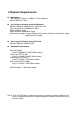
1.4 System Requirements Networking LAN: 10Base-T Ethernet / 100Base-TX Fast Ethernet WLAN: IEEE 802.11b/g Accessing the Camera using Web Browser Platform: Windows 2000/XP/Vista, Macintosh OSX CPU: Intel Pentium III 350MHz or above RAM: 128MB or above VGA Resolution: 800x600 or above Web browser support: Internet Explorer 6.0 or above, Mozilla Firefox 2.
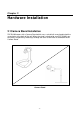
Chapter 2 Hardware Installation 2.1 Camera Stand Installation ZVC7610W comes with a Camera Stand which uses a swivel ball screw head to lock the screw-holes at the back of the unit. When the stand is attached to your ZVC7610W, you can place it anywhere by mounting it through the three screw-holes at the bottom of the Camera Stand.
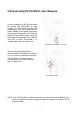
2.2 Connecting ZVC7610W to Your Network Use the provided RJ-45 Ethernet cable to connect the ZVC7610W to your network. The ZVC7610W will power ON automatically after you connect the AC Power Adapter to the power connector. You may verify the power status from the Power LED on the front panel. Once you completed the connection, Link LED will start flash in green, ZVC7610W is at standby mode, and it is ready to use.
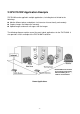
2.3 ZVC7610W Application Example ZVC7610W can be applied in multiple applications, including but not limited to the followings: Monitor different places and objects via Internet or Intranet locally and remotely. Capture images and video clips remotely. Upload images and email messages with the images. The following diagram explains one of the most typical applications for the ZVC7610W. It also provides a basic example of the ZVC7610W installation.
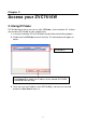
Chapter 3 Access your ZVC7610W 3.1 Using IP Finder ZVC7610W comes with an easy to use utility, IP Finder, in the Installation CD. It allows you to find the ZVC7610W on your network easily. 1. Insert the Installation CD to CD-ROM drive and initiate the Auto-Run program 2. Double-click the IP Finder to launch the utility. The control panel will appear as below.
3.2 Login to your ZVC7610W 1. Open your web browser and enter the ZVC7610W IP address on the address bar. a. Default IP address: http://192.168.0.30 then press [Enter] 2. The login window will appear, enter the username and password then press OK to access to the main screen of the ZVC7610W Web Configuration. a. Default Username: admin (all lowercases) b. Default Password: admin (all lowercases) Enter the IP address of the camera here. Enter the User name and Password.
After you login into the ZVC7610W Web Configuration main screen, the following screen will appear. Zoom In Button Nightmode Button Live View/Setup Switch Camera Information Function Button Live View Image The Web Configuration provides you with many useful information and functions, including: Camera Information – Display the location of your ZVC7610W with the current date & time. This information can be modified in the Web Configuration.
3.3 IP Address Configuration You have to check the IP address of your computer if you failed to access the ZVC7610W. When connecting the ZVC7610W directly to your computer, you have to set up your computer IP address within the same subnet in order for them to communicate correctly. 1. On your computer, click Start > Control Panel to open the Control Panel window 2. Double-click Network Connection to open the Network Connection window 3.
Chapter 4 ZVC7610W Configuration 4.1 Using the Web Browser To configure the ZVC7610W with your web browser, click Setup on the main page. The Web Configuration will start from the Basic page. The Web Configuration contains settings that are required for the ZVC7610W in the left menu bar, Smart Wizard, Basic, Network, Video, Event Server, Motion detect, Event Config, Tools and Information.
4.2 Using Smart Wizard ZVC7610W Smart Wizard lets you configure the camera easily and quickly. The wizard will guide you through the necessary settings in detailed instructions of each step. To start the wizard, click Smart Wizard in the left menu bar. Step 1.
Step 2. IP Settings * Select the IP setting according to your network: DHCP, Static IP, or PPPoE. Step 3. Email Settings * Enter the required information for email with image.
Step 4. Wireless Networking * Check the Enable box to enable wireless function of ZVC7610W. Complete all required information and click Next>. Step 5. Confirm Settings The last step shows the configuration of your ZVC7610W. After all settings are confirmed, click Apply to finish the wizard and it will reboot the ZVC7610W automatically. Click
4.3 Basic Setup The Basic menu contains three sub-menus, Camera Name, Location, Date & Time, and User management. Basic >> System Basic - Camera Name: Enter a description for your ZVC7610W - Location: Enter a description of your ZVC7610W location Indication LED It allows you to set LED illumination as your desired. There are two options: Normal and OFF. Basic >> Date & Time Date & Time - TimeZone: Select the proper time zone for the region from the drop-down menu.
4.4 Network Settings The Network menu contains three sub-menus that provide the network settings for the camera, such as the IP Setting, DDNS Setting, IP Filter, and Wireless network. Network >> Network IP Setting allows you to select the IP address mode and set up the related configuration. - DHCP: Select this option when your network uses the DHCP server. When ZVC7610W starts up, it will be assigned an IP address from the DHCP server automatically.
IP Enter IP Address of ZVC7610W Default IP Address: 192.168.0.30 Subnet Mask Enter Subnet Mask of ZVC7610W Default Subnet Mask: 255.255.255.0 Default Gateway Enter Default Gateway of ZVC7610W Default address: 192.168.0.1 Primary/ Secondary DNS DNS (Domain Name System) translates domain names into IP addresses. Enter the Primary and Secondary DNS that provided by ISP. - PPPoE: Select this option when you use a direct connection via the ADSL modem. Enter your PPPoE Account User Name and Password.
Network >> IP Filter The IP Filter setting allows the administrator limits users within a range of IP address to access the ZVC7610W. Start/End IP Address Assign a range of IP address that is NOT allowed to access the ZVC7610W. Enter the Start IP address and End IP address. Click Add to save the setting. You can repeat this step to assign more than one range of IP address. For example, when you enter 192.168.0.50 for the Start IP Address and 192.168.0.
- Wireless Mode: Select the type of wireless communication for ZVC7610W Infrastructure Ad-Hoc - Channel: Select the appropriate wireless channel - Authentication: Select an authentication method to secure ZVC7610W from being used by unauthorized wireless users. Open Shared-key WPA-PSK WPA2-PSK Open Shared-key WPA-PSK/ WPA2-PSK Default setting of authentication mode. It communicates the encryption key across the wireless network.
AES (Advanced Encryption Standard) uses to ensure the highest degree of security and authenticity for digital information. Pre-Shared Key: This is used to identify each other in the network. Enter the name in the box, and this name must match the Pre-shared key value in the remote device.
4.5 Video Setup Video menu contains three sub-menus that provide video settings for the ZVC7610W.
Video >> Camera Image Setting - Brightness: Adjust the brightness level from 0 ~ 100 - Contrast: Adjust the contrast level from 0 ~ 100 - Saturation: Adjust the colors level from 0 ~ 100 Click Default to restore the default settings of the three options above. - Mirror: Select Horizontal to mirror the image horizontally.
4.6 Event Server Configuration The Event Server menu contains three sub-menus that allow you to upload images to FTP and send emails with images. After you complete the required settings for FTP, or Email, click Test to test the configuration to see if it is correct or not. After test is successful, click Apply.
Event Server Setting>> FTP FTP - Host Address: Enter the IP address of the target FTP server - Port Number: Enter the port number for the FTP server - User Name: Enter the user name to login to the FTP server - Password: Enter the password to login to the FTP server - Directory Path: Enter the destination folder for uploading the images, for example: /Test/ - Passive Mode: Select Enable to enable the passive mode Event Server Setting >> Email Email - SMTP Server Address: Enter the mail server address, f
4.7 Motion Detect The Motion Detect menu contains the command and option that allow you to enable and setup the motion detection feature of the ZVC7610W. It provides up to two detecting areas. To enable the detecting areas, select Window 1 or 2 from the drop-down list, and select Enable. When the detecting area(s) is enabled, you can use the mouse to move the detecting area(s) and change the area coverage.
4.8 Event Config The Event Config menu contains four sub-menus that provide the commands to configure event profiles. Event Configuration >> General Setting - Snapshot/Recording Filename Prefix: You can assign a given prefix to each new captured file. Leave this option blank to use the default setting. Event Configuration >> Arrange Schedule Profile This sub-menu displays the scheduled profile(s). To customize the profile, click Add and enter a description for the profile in the prompt dialog window.
- Profile Name: Display profile name(s) that you added to the Schedule Profiles list - Weekdays: Select the day(s), Monday to Friday, which you want to assign in the schedule profile separately. Assigned weekday(s) will display in green color - Time List: Display the period of time that you have assigned within the selected weekday(s). Click Add this to all weekdays to assign the same period of time to every weekday(s). Click Delete this from all weekdays to remove the selected period from every weekday(s).
4.9 Tools The Tools menu provides commands that allow you to restart and/or reset the ZVC7610W. You can also backup, restore your configuration, and upgrade firmware for the ZVC7610W. Factory Reset Click Reset to restore all factory default settings for the ZVC7610W. System Reboot Click Reboot to restart the ZVC7610W. It will power OFF the under then power ON automatically. ZVC7610W configuration will be retained after System Reboot.
4.10 Information The Information menu displays the current configuration and events log of the ZVC7610W. Device Info Display the Basic, Video, and Network settings of the ZVC7610W. System Log This table displays all events log recorded by the system.
Chapter 5 A PPENDIX A.1 Specification Image Sensor Sensor Resolution 1/4” color CMOS 640x480 Video Compression Video resolution MJPEG VGA/QVGA/QQVGA; 30fps max. System Hardware Processor RAM ROM Power ARM9 base 16MB SDRAM 4MB NOR Flash DC 5V Communication LAN WLAN Protocol support User Interface LAN Reset LEDs Software OS Support Browser Software 10/100Mbps Fast Ethernet Auto-sensed, Auto-MDIX IEEE 802.
A.2 Glossary of Terms NUMBERS 10BASE-T 100BASE-TX A ADPCM AMR Applet ASCII ARP AVI B BOOTP C Communication Connection D DHCP 10BASE-T is Ethernet over UTP Category III, IV, or V unshielded twisted-pair media. The two-pair twisted-media implementation of 100BASE-T is called 100BASE-TX. Adaptive Differential Pulse Code Modulation, a new technology improved from PCM, which encodes analog sounds to digital form.
DNS E Enterprise network Ethernet F Fast Ethernet Firewall G Gateway Group H HEX can be added to a network without the hassle of manually assigning it a unique IP address. DHCP allows the specification for the service provided by a router, gateway, or other network device that automatically assigns an IP address to any device that requests one. Domain Name System is an Internet service that translates domain names into IP addresses. Since domain names are alphabetic, they're easier to remember.
I Intranet Internet Internet address IP IP address ISP J JAVA L LAN M MJPEG MPEG4 This is a private network, inside an organization or company that uses the same software you will find on the public Internet. The only difference is that an Intranet is used for internal usage only. The Internet is a globally linked system of computers that are logically connected based on the Internet Protocol (IP). The Internet provides different ways to access private and public information worldwide.
mobile telephones. N NAT Network NWay Protocol P PCM PING PPPoE Protocol Network Address Translator generally applied by a router that makes many different IP addresses on an internal network appear to the Internet as a single address. For routing messages properly within your network, each device requires a unique IP address. But the addresses may not be valid outside your network. NAT solves the problem.
FDDI, or Ethernet. The Router Information Protocol (RIP),a part of the Transmission Control Protocol/Internet Protocol (TCP/IP) suite, forwards packets from one network to another using the same network protocol. R RJ-45 Router RTP RTSP S Server SIP SMTP SNMP Station Subnet mask T (TCP/IP) Transceiver U UDP RJ-45 connector is used for Ethernet cable connections. A router is the network software or hardware entity charged with routing packets between networks.
User Name Utility UTP W WAN WEP Windows WPA WPA2 The USERNAME is the unique name assigned to each person who has access to the LAN. It is a program that performs a specific task. Unshielded twisted-pair. UTP is a form of cable used by all access methods. It consists of several pairs of wires enclosed in an unshielded sheath. Wide-Area Network.