
Specifications


Compressor
The input signal from the bass
guitar is compressed to
achieve a uniform volume
level.
Higher values result in
stronger compression.
Limiter
Limits the input signal with
faster response than the
compressor effect. Serves to
prevent overload of other
modules.
Higher values result in more
effective limiting.
Fat Wah
Wah with wide emphasis
frequency range and a solid,
fat sound.
When set in this range, the
emphasized frequency is
shifted, depending on the
dynamics of the bass guitar
input. Higher values result in a
more pronounced wah
effect.
When this value is selected,
wah can be controlled using
the pedal FP01 connected
to the CONTROL IN jack.
Resonant Wah
Strongly emphasizes a narrow
range while varying the
emphasized frequency. Can be
used as pedal wah or auto
wah.
When set in this range, the
effect functions as auto wah.
Higher values result in a
more pronounced auto wah
effect.
When this value is selected,
wah can be controlled using
the pedal FP01 connected
to the CONTROL IN jack.
Distortion Type
A total of eight effect types are
available, including four
different distortion types and
four effects which produce a
clean sound without distortion.
Clean sound with flat
response.
Clean sound with lean
midrange.
Fat sound with prominent
midrange.
Clean sound, ideal for slap
type playing.
Drive sound with prominent
midrange that maintains a
distinct character also in
ensemble playing.
Husky vintage sound.
Strongly distorted fuzz
sound.
Thrashing metal type sound.
Distortion Gain
Sets the intensity of distortion
type effects and the depth of
clean type effects.
Higher values result in
stronger distortion or greater
effect intensity.
ZNR module
Determines the settings for
Zoom Noise Reduction.
AMP module
Simulates the sonic
characteristics of a bass guitar
amplifier.
Both modules together form
the ZNR/AMP block.
Higher values result in more
effective noise reduction in
the no-signal condition.
Choose the highest setting
that will remove noise
without making the
instrument sound unnatural
at the trailing edge (when the
sound decays into silence).
A1: Amp simulator only is
active.
A2 - A9: ZNR is also used.
Higher values result in more
effective noise reduction.
4band EQ
Allows boost and cut in the
presence, high, midrange, and
low range, with 50 available
settings.
Lower values result in a
stronger high-range cut and
low-range boost.
Lower values result in a
lower boosted frequency.
Lower values result in a
stronger presence-range
boost.
Yields flat frequency
response.
Higher values result in a
stronger high-range boost.
Higher values result in a
higher boosted frequency.
Higher values result in a
stronger presence-range
and low-range boost, giving
a firm, solid sound.
Phase Shift
Applies a phase-shifted
component to the direct sound.
The amount of shift varies
periodically, giving a
breathing effect.
Higher values result in a
stronger effect.
.
Chorus1
Simple chorus which adds a
component with periodically
changing pitch to the direct
sound. Suitable for enhancing
body while maintaining a
clean sound.
Higher values result in a
stronger effect.
Chorus2 (Crystal Chorus)
Distinct ensemble chorus with
depth and ambience.
Higher values result in a
stronger effect.
Flanger
Adds a very short delay to the
direct sound and varies the
delay time periodically,
resulting in a peculiar sound
character.
Higher values result in a
stronger effect.
Synth
Bass synthesizer sound that is
controlled by the bass input
signal. Does not respond to
chord input.
To prevent unwanted results,
you should carefully pick
single tones.
Synthesizer sound created
by adding second harmonic
noise to strong bass
(synthesizer sound only)
Bright synthesizer sound
with pronounced high-range
resonance (synthesizer
sound only)
Soft synthesizer sound with
subdued harmonics
(synthesizer sound only)
S1 + some direct sound.
S2 + some direct sound.
S3+ some direct sound.
S1+ direct sound 1:1.
S2+ direct sound 1:1.
S3+ direct sound 1:1.
Octaver
Adds a one-octave lower
sound to the direct sound,
making the sound more full-
bodied. Can also be used
together with the chorus
effect. Optional pedal can be
used for controlling the pitch.
Higher values result in
stronger lower-octave
sound.
Octaver and chorus are used
together. Chorus is fixed, but
higher values result in
stronger lower-octave
sound.
When this value is selected,
the pitch can be controlled
within the range to one
octave higher, using the
pedal FP01 connected to
the CONTROL IN jack.
When this value is selected,
the pitch can be controlled
within the range to one
octave lower, using the
pedal FP01 connected to
the CONTROL IN jack.
Delay
Conventional digital delay
with a delay time of up to 370
ms. By monitoring this effect
in stereo, you can achieve a
ping-pong delay.
Higher values result in longer
delay time.
Mix and feedback are also
optimized.
Hall Reverb
Simulates the acoustics of a
hall.
Higher values result in longer
reverb time.
Mix setting is also
optimized.
Room Reverb
Simulates the acoustics of a
room.
Higher values result in longer
reverb time.
Mix setting is also
optimized.
Patch Level
Allows setting the level of
individual patches.
This setting is stored for each
patch like the effect
parameters.
Higher values result in
higher level.
(1 – 30)
Setting range:
(r1 – r9)
Setting range:
Setting range:
(H1 – H9)
Setting range:
(d1 – d9)
Setting range:
(07 – 09)
(01 – 06)
Setting range:
(F1 – F9)
Setting range:
(c1 – c9)
Setting range:
(C1 – C9)
Setting range:
(P1 – P9)
Setting range:
(41 – 50)
(31 – 40)
(26 – 30)
(25)
(21 – 24)
(11 – 20)
Setting range:
(1 – 10)
Setting range:
(A1 – A9)
(1 – 9)
Setting range:
(1 – 30)
Setting range:
(Thrash)
(Fuzz)
(Vintage)
(Drive )
(Slap)
(Fat)
(Clean2)
(Clean1)
(rP)
(r1 – r8)
Setting range:
(FP)
(F1 – F8)
Setting range:
(L1 – L9)
Setting range:
(C1 – C9)
Setting range:
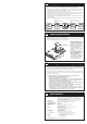
The 506 comes with 24 predefined patches that have been programmed at the factory. However,
the 506 offers many more possibilities for combining effects in innovative ways. To discover these
possibilities, we recommend that you try out the editing function, which lets you create your own
patches. The mode in which patches can be edited is called the Edit mode.
To switch from normal Play mode to Edit mode, briefly press the EDIT key. Do not keep the EDIT
key depressed, because if the key is held for 1 second, the Bank Hold mode will be activated.
Immediately after
switching from the Play
mode to the Edit mode, the
parameter cursor flashes at
the highest position
(COMP module),
regardless of which patch
was selected. The COMP
module setting of the
current patch is shown on
the display.
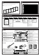
While Edit mode is active, each push of the EDIT key causes the parameter cursor to move one position down.
The flashing position shows which module is selected for editing. The relation between parameter cursor LEDs and modules is
as shown below.
1st parameter cursor LED: COMP module setting
2nd parameter cursor LED: DIST module distortion type setting
3rd parameter cursor LED: DIST module distortion gain setting
4th parameter cursor LED: ZNR and AMP block settings
5th parameter cursor LEDs: EQ module setting
6th parameter cursor LED: MOD module setting
7th parameter cursor LED: DLY/REV module setting
8th parameter cursor LED: PATCH level setting
Use VALUE + / - keys to change parameters.
For an explanation of the various parameters, please refer to the section "Effect Parameters".
When the EDIT key is pressed while the 8th parameter cursor LED flashes, the Edit mode is canceled and the unit returns to
the Play mode.
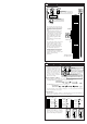
Editing Patches
Effect Parameters
(
1) While still in Play mode, select
the patch you wish to edit.
(2) Press the EDIT key to
activate the Edit mode.
(1) Use the EDIT key to
select the parameter
you wish to change.
(2) Use the VALUE + / - keys
to adjust the parameter.
(3) When the 8th parameter cursor LED
is flashing, press the EDIT key to return
to the Play mode.
12
11
COMP module DIST module ZNR/AMP block
EQ module MOD module DLY/REV module PATCH Level
Each effect module in the 506
can be considered as a single
compact effect device. Adjusting parameters
then is equivalent to selecting the type of
effect device or turning the knobs on an
effect device. What is called a patch
corresponds to a collection of effect devices
connected in various ways and set to ON or
OFF.
As you will know if you have used several
individual effect devices in a performance
before, not all devices will be switched on
all the time. Depending on the mood of the
song and other factors, devices will be
switched on and off in different
combinations. The same applies to the 506.
The on/off timing and combination of effect
modules are important aspects in creating a
certain sound.
Except for the distortion gain (3rd
parameter cursor position) and patch level
setting (lowest parameter cursor setting),
the flashing parameter cursor indicates that
the corresponding effect module can be
turned on or off.
The ZNR and AMP modules are turned on
and off together. When wishing to disable
them individually, you must do this by
setting the parameters accordingly.
Effect modules can be switched on and off in
three ways.
1. Using the VALUE + / - keys
When using the VALUE + key to increase
the parameter value, the setting following
the maximum value is the "effect off" setting.
Similarly, when using the VALUE - key to
decrease the parameter value, the setting
before the minimum value is the "effect off"
setting. When the VALUE + key is pressed
once in the "effect off" condition, the effect
is turned on and the minimum value is set.
When the VALUE - key is pressed once in
the "effect off" condition, the effect is turned
on and the maximum value is set.
2. Using a shortcut
Pressing both VALUE + / - keys together for
an effect module functions as a shortcut.
Repeating the shortcut procedure several
times turns the effect off. Performing the
shortcut when the effect is off turns it on and
sets the minimum parameter value.
3. Using the patch pedals
Pressing both patch pedals together for an
effect module turns the effect off. Pressing
both patch pedals together when the effect is
off turns it on and restores the previously
selected parameter value.
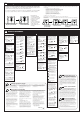
Effect off indication
Effect module on/off switching
2
EFFECT OFF=
HINT
As described in "Editing
Patches", parameters to be
edited are selected by repeatedly pressing
the EDIT key, but you can also use the patch
pedals for this purpose.
Pressing the patch UP pedal (right pedal)
moves the parameter cursor (the selected
parameter) up.
Pressing the patch DOWN pedal (left pedal)
moves the parameter cursor (the selected
parameter) down.
Selecting parameters to change
1
HINT
Parameter setting shortcut
Normally, parameter values are set by tapping the
VALUE + or VALUE - key once for each increment.
To allow quick operation in effect modules which contain
more than one effect, you can use the shortcut function which
is activated by pressing both VALUE keys simultaneously. For
example, if you are currently at the "Delay" parameter of the
DLY/REV module and the current setting is "d5", you would
need to press the VALUE + key 18 times to set the "Room"
effect to "r5". However, you can achieve the same effect by
activating the shortcut twice and then pressing the VALUE +
key 4 times.
Volume control with FP01
When the optional expression pedal FP01 is
connected to the CONTROL IN jack, it can also be
used for adjusting the output volume of the 506. However, if
the COMP module parameter is set to a range which activates
pedal wah for Fat Wah or Resonant Wah, or if the Octaver
parameter in the MOD module is set to pedal pitch (Pu or
Pd), this setting has priority and the pedal controls the effect.
In other cases, the pedal controls the volume between the EQ
module and the MOD module. As opposed to a volume pedal
connected after the 506, the level can be adjusted without
affecting the sonic impression of reverb and delay effects.
Master level adjustment
The 506 also lets you set the overall output level,
separately from individual patch levels.
The master level can be adjusted in Play mode, as follows.
Keep both VALUE keys depressed for at least 1 second. The
current master level is then shown on the display for 1 second.
While the level is displayed, you can use the VALUE + / - keys
to change it. The setting range is 0- 50. At "40", the level is
identical to the individual patch level.
The master level setting is not stored by the unit. After the
power has been turned off, the master level must be set again.
5
4
3
HINT
HINT
HINT