Operation Manual © ZOOM Corporation Reproduction of this manual, in whole or in part, by any means, is prohibited.
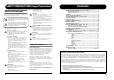
Contents SAFETY PRECAUTIONS Usage Precautions • High humidity or moisture • Excessive dust or sand • Excessive vibration or shock SAFETY PRECAUTIONS In this manual, symbols are used to highlight warnings and cautions for you to read so that accidents can be prevented. The meanings of these symbols are as follows: This symbol indicates explanations about dangerous matters. If users ignore this symbol and handle the device the wrong way, bodily injury and damage to the equipment could result.
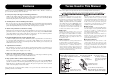
Features Terms Used in This Manual Thank you for selecting the ZOOM G2 (hereafter simply called the "G2"). The G2 is a multi effect processor with the following features and functions. This section explains some important terms that are used throughout the G2 documentation. IN ● Latest processing technology for outstanding performance 96 kHz / 24 bit sampling (with 32 bit internal processing) assures excellent sound quality.
Controls and Functions / Connections Controls and Functions / Connections Parameter knobs 1 - 3 Top Panel Module selector These knobs allow changing the level of effect parameters or of the overall patch. During rhythm playback, the knobs let you select a pattern, set the tempo, and adjust the rhythm volume. Switches between play mode and edit mode. In edit mode, the knob selects the module for operation.
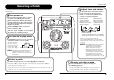
Selecting a Patch Selecting a Patch Adjust tone and volume To try out the various effects of the G2, we recommend that you simply play your instrument while switching patches. To adjust the effect sound and volume levels in play mode, the Parameter knobs 1 – 3 can be used. Each knob controls a specific parameter. Turn power on Use a monaural shielded cable to connect the guitar to the [INPUT] jack of the G2.
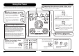
Using the Tuner Using the Tuner The G2 incorporates an auto-chromatic tuner. To use the tuner function, the built-in effects must be bypassed (temporarily turned off) or muted (original sound and effect sound turned off). Adjusting the reference pitch of the tuner If required, you can fine-adjust the reference pitch of the G2 tuner. The default setting after power-on is center A = 440 Hz. Turn Parameter knob 1.
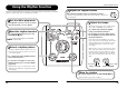
Using the Rhythm Function Using the Rhythm Function The G2 has a built-in rhythm function that plays realistic drum sounds in various patterns. The rhythm function is available in play mode or in the bypass/mute condition. Adjust the rhythm volume To adjust the rhythm volume, turn Parameter knob 3. When you turn the Parameter knob, the current setting (0 – 30) is shown on the display.
Editing a Patch Editing a Patch Terminate the edit mode The patches of the G2 can be freely edited by changing the effect parameter settings. Try editing the currently selected patch to create your own sound. Select the effect module To terminate the edit mode and NOTE When you return to play mode and select another patch, the changes return to the play mode, set the you have made in edit mode will be Module selector to the "PLAY" lost unless you store the patch position. first.
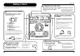
Storing/Copying Patches Storing/Copying Patches An edited patch can be stored in a bank of the user area (A – d). It is also possible to store an existing patch in another location to create a copy. To cancel the store process To cancel the store process, operate the Module selector before pressing the [STORE] key again ( ). In play mode or edit mode, press the [STORE] key. The bank and patch number are shown on the display as a flashing indication.
Using an Optional Foot Switch or Pedal Using an Optional Foot Switch or Pedal The G2 is equipped with a [CONTROL IN] jack designed for connection of an optional foot switch or expression pedal. This section explains how to use these accessories. Using the foot switch (FS01) Connecting the optional foot switch FS01 to the [CONTROL IN] jack allows changing banks with the foot switch while the unit is in play mode.
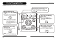
Restoring Factory Defaults Linking Effects In the factory default condition, the patches of the user area (A0 – d9) contain the same settings as the patches of the preset area (00 – 39). Even after overwriting the user patches, their original content can be restored in a single operation ("All Initialize" function). The patches of the G2 consist of nine serially linked effect modules, as shown in the illustration below.
Effect Types and Parameters Effect Types and Parameters COMP COMP (Compressor) module Attenuates high-level signal components and boosts low-level signal components, thereby keeping the overall signal level within a certain range. How to read the parameter table SENSE Effect parameters 1 – 3 These are the parameters that can be adjusted with Parameter knobs 1 – 3 when the effect type is selected. The setting range for each parameter is shown.
Effect Types and Parameters Effect Types and Parameters RING MODULATOR RG rG This effect produces a metallic ringing sound. Adjusting the FREQUENCY parameter results in a drastic change of sound character. POSITION FREQUENCY bF, AF Selects the connection position of the WAH/EFX module. Available settings are "bF" (before DRIVE module) and "AF" (after EQ/EXTRA EQ module). 1 – 50 Adjusts the frequency that is used for modulation.
Effect Types and Parameters Effect Types and Parameters FLANGER FL FL This effect produces a resonating and strongly undulating sound. EQ EQ (Equalizer) module Allows adjusting the three main bands (BASS, MIDDLE, TREBLE) of the six-band equalizer. BASS ±12 MIDDLE 160Hz Adjusts the low frequency range level. ±12 800Hz Adjusts the mid frequency range level. TREBLE ±12 3.2kHz Adjusts the high frequency range level.
Effect Types and Parameters Effect Types and Parameters TAPE ECHO TE tE This effect simulates a tape echo. 1 – 99, 1.0 – 2.0 TAP Adjusts the delay time. In the range from 10 – 990 ms, the adjustment is made in 10-ms steps (1 – 99). For 1 second and above, the adjustment is made in 100-ms steps (1.0 – 2.0). TIME DELAY DELAY module FEEDBACK 0 – 98, 1.0 Adjusts the feedback amount. MIX 0 – 98, 1.0 Adjusts the level of the effect sound mixed to the original sound.
Effect Types and Parameters Specifications CONTROL CONTROL module Serves for making pedal settings and lets you control the foot switch function and master level setting applying to all patches. RTM DESTINATION See Table 4 When an expression pedal (FP01/FP02) is connected to the [CONTROL IN] jack, this selects the modulation target module for the RTM function (See Table 4).
G2 Preset Pattern TimSig # 1 # 8beat_1 PatternName 4/4 21 POP_3 PatternName TimSig 4/4 2 8beat_2 4/4 22 DANCE_1 4/4 3 8beat_3 4/4 23 DANCE_2 4/4 4 8shufle 4/4 24 DANCE_3 4/4 5 16beat_1 4/4 25 DANCE_4 4/4 6 16beat_2 4/4 26 3per4 3/4 7 16shufle 4/4 27 6per8 3/4 8 ROCK 4/4 28 5per4_1 5/4 9 HARD 4/4 29 5per4_2 5/4 10 METAL_1 4/4 30 LATIN 4/4 11 METAL_2 4/4 31 BALLAD_1 4/4 12 THRASH 4/4 32 BALLAD_2 3/4 13 PUNK 4/4 33 BLUES_1 4/4 1
C7 C MAJOR HARMONY A8 A9 B0 C9 With this patch selected, your electric guitar will start to sound like an acoustic electric guitar. We would recommend you to combine this patch with the single-coil type front pick-up. You can also use this patch actively to create the clean ensemble effect. ACOUSTIC SIM Even if you are the type of guitar player who is proud of wailing solos, you may sometimes want to use thrash power chords (with some muting-technique on the bridge).
Modeling Description MESA/BOOGIE Mark III … Reference for drive effect types and its original models. EFFECT TYPE : BC CRUNCH bC bC The origin of the MESA/BOOGIE amplifier was the modified Fender Princeton. Randall Smith, an amp tech in San Francisco, souped up those small guitar amps to put out 100w power and sold them. The first model was called “Mark I”. Carlos Santana tried one and said, “Shit man, that little thing really Boogies! “ -which gave the amplifier the brand name “BOOGIE.