Operation Manual You must read the Usage and Safety Precautions before use. © 2018 ZOOM CORPORATION Copying or reprinting this manual in part or in whole without permission is prohibited. Product names, registered trademarks and company names in this document are the property of their respective companies. All trademarks and registered trademarks in this document are for identification purposes only and are not intended to infringe on the copyrights of their respective owners.
■ Operation Manual overview You might need this manual in the future. Always keep it in a place where you can access it easily. The contents of this document and the specifications of the product could be changed without notice. • Windows® is a trademark or registered trademark of Microsoft® Corporation. • Macintosh, macOS and iPad are trademarks or registered trademarks of Apple Inc. • The SD, SDHC and SDXC logos are trademarks.
Introduction Thank you very much for purchasing a ZOOM lowing features. LiveTrak (hereafter, " ").The has the fol- 20-channel digital mixer & multitrack recorder The combines a digital mixer with 20 total input channels (16 mono and 2 stereo), a multitrack recorder that can simultaneously record up to 22 tracks, and a 22-in/4-out USB audio interface.
Contents ■ Operation Manual overview ………………… 1 Introduction ……………………………………… 2 Names and functions of parts …………………… 4 Top ………………………………………………… 4 Rear panel ……………………………………… 19 Equipment connection examples ……………… 21 Live PA system ………………………………… 21 Display overview ………………………………… 23 Home Screen …………………………………… 23 Checking project information ……………… Saving projects to USB flash drives ……… Importing projects from USB flash drives … Checking, deleting and moving to marks … 62 63 65 67 Audio files ………………………………………
Names and functions of parts Top Input channel section 1 MIC/LINE input jack 2 48V switch/indicator 3 Hi-Z switch 4 PAD switch 5 SIG indicator 6 GAIN knob 7 COMP knob 8 SEL button 9 REC/PLAY button 1 MIC/LINE input jack These input jacks have built-in mic preamps. Connect mics, keyboards and guitars to them. These can be used with both XLR and 1/4-inch (balanced or unbalanced) phone plugs. 2 48V switch/indicator This turns +48 V phantom power on or off. Turn this on ( put jacks 1–4, 5–8, 9–12 or 13–16.
Turn it on ( ) when connecting a guitar or bass guitar. 4 PAD switch This attenuates (reduces) the input signal of the equipment connected to the MIC/LINE input jack by 26 dB. Turn this on ( ) when connecting line level equipment. 5 SIG indicator This indicator shows the signal level after adjustment by the GAIN knob. The indicator color changes according to the signal level. Adjust so that it does not light red.
! LINE input jacks (TS) " LINE input jacks (RCA) # USB button $ MUTE button % SOLO button & Level meter ( Channel fader ! LINE input jacks (TS) Use these input jacks to connect line level equipment. For example, connect keyboards or audio devices. These can be used with 1/4-inch (unbalanced) phone plugs. NOTE If only the left LINE input jack (TS) channel is connected, it will be handled as a mono channel. " LINE input jacks (RCA) Use these input jacks to connect line level equipment.
# USB button This switches the signals input to channels 17/18 (or 19/20). Lit: audio return signal output from the computer Unlit: LINE input jacks NOTE Connect the to a computer as an audio interface. (→ "Connecting to a computer") $ MUTE button This mutes or unmutes signals. To mute the channel, press this button to light it. HINT This has no effect on recording to the SD card. % SOLO button When a SOLO button is ON, the pre-fader signal can be heard from the PHONES jack.
CHANNEL STRIP section 1 SEND EFX1 knob 3 HIGH knob 2 SEND EFX2 knob 4 MID FREQ knob 7 PAN knob 5 MID knob 8 LOW CUT knob 6 LOW knob 9 Φ (polarity) button ! EQ OFF button 1 SEND EFX1 knob The amount that can be sent to the SEND EFX 1 bus can be set from −∞ to +10 dB. 2 SEND EFX2 knob The amount that can be sent to the SEND EFX 2 bus can be set from −∞ to +10 dB. 3 HIGH knob This adjusts the boost/cut of high-frequency equalization.
6 LOW knob This adjusts the boost/cut of low-frequency equalization. Type: shelving Gain range: −15 db – +15 dB Frequency: 100 Hz 7 PAN knob This adjusts the position in the stereo output bus. On a stereo input channel, this adjusts the volume balance between the left and right channels. 8 LOW CUT knob This adjusts the high-pass filter, which cuts low frequencies. Signals below the set frequency are attenuated 12 dB/octave.
FADER MODE section 1 MASTER and A–F buttons 1 MASTER and A–F buttons These switch between the mixes output from the MASTER OUT and MONITOR OUT A–F jacks. MASTER button: Use to show and adjust the mix output from the MASTER OUT jacks. A–F buttons: Use to show and adjust the mixes output from the MONITOR OUT A–F jacks. NOTE The following parameters can have separate settings for the MASTER and A–F mixes.
Send effect (SEND EFX) section 1 Effect type 1 list 1 Effect type 2 list 2 EFX1 TYPE knob 2 EFX2 TYPE knob 3 Parameter 1 knobs 3 Parameter 2 knobs 4 MUTE button 5 SOLO button 6 EFX RTN level meters 7 EFX RTN fader 1 Effect 1/2 type lists These are lists of the built-in effects. The effects are separated into two sets, and one effect from each set can be used. The names of the currently selected effects light. An effect name blinks when being selected.
3 Parameter 1 and 2 knobs Use these to adjust the parameters for the selected effects. See "Send effect specifications" for the parameters of each effect. 4 MUTE button This mutes or unmutes the signal sent from the built-in effect. To mute the channel, press this button to light it. 5 SOLO button When a SOLO button is ON, the signal before the EFX 1/2 RTN fader can be heard from the PHONES jack. At such times, the SELECT knob will automatically select SOLO.
SCENE section 1 ON button 2 RESET button 3 1–9 buttons 4 RECALL button 5 SAVE button 1 ON button Press this button, lighting it, to use the scene function 2 RESET button Press this button to reset the current mixer settings to the factory defaults. 3 1–9 buttons Use these buttons to select the scene to use to save the current mixer settings and to load saved scenes. If the current mixer settings match the settings of a scene, the corresponding number button will light. This unit can save up to 9 scenes.
Output section 2 MONITOR OUT A–F jacks 3 MONITOR OUT A–F knobs 1 MASTER OUT jacks 4 MONITOR OUT A–F switches 5 MONITOR OUT A–F PHONES/SPEAKER switches 6 SELECT knob 7 VOLUME knob 8 PHONES jack 9 MASTER REC/PLAY button ! MASTER MUTE button " Master level meters # Master fader 1 MASTER OUT jacks These jacks output signals after volume adjustment by the master fader. Connect them to a power amplifier, a PA system or speakers with built-in amplifiers, for example.
3 MONITOR OUT A–F knobs Use to adjust the volumes of the signals output from the MONITOR OUT A–F jacks. 4 MONITOR OUT A–F switches These switch the signals output from the MONITOR OUT A–F jacks. Status MASTER ( A–F ( ) ) Explanation The signal after adjustment by the master fader will be output. The signals set in the FADER MODE section are output. 5 MONITOR OUT A–F PHONES/SPEAKER switches Use these to select the type of equipment connected to the MONITOR OUT A–F jacks.
# Master fader This adjusts the signal levels output from the MASTER OUT jacks in a range from −∞ to +10 dB. NOTE If the actual channel fader position differs from the channel fader position recalled using the scene function, for example, the level meter will show the recalled fader position. When AUTO REC is activated, however, the master fader position will not be shown.
RECORDER section 1 Slate mic 2 SLATE button/indicator 4 MENU button 5 Selection encoder 6 TEMPO button/indicator 8 PLAY/PAUSE button/in- 3 Display dicator 9 REC button/indicator ! OVER DUB button/indicator 7 STOP button " FF button # REW button 1 Slate mic This is a built-in mic for recording comments. This mic input is active while the SLATE button is being pressed. It can be set to record on channels 1–20, the MASTER channel or all channels.
7 STOP button This stops the recorder. 8 PLAY/PAUSE button/indicator This starts and pauses recorder playback. The indicator shows the playback status as follows. Status Explanation Lit green The recorder is playing back. Blinking green Playback is paused. 9 REC button/indicator This puts the recorder in recording standby. The indicator shows the recording status as follows. Status Explanation Lit red The recorder is recording or in recording standby. Blinking red Recording is paused.
! REMOTE jack 9 CONTROL IN jack 8 SD card slot 7 SAMPLE RATE switch switch 6 CLASS COMPLIANT MODE 5 USB DEVICE port 4 MODE switch 3 USB HOST port 2 DC IN 12V AC adapter connector 1 POWER switch Rear panel 1 POWER switch This turns the unit on and off. Switch to — to turn the power on. Switch to to turn the power off. When the POWER switch setting is changed to OFF, the current mixer settings are automatically saved in the unit and in the settings file in the project folder on the SD card.
6 CLASS COMPLIANT MODE switch Use this to turn Class Compliant Mode ON/OFF. Set it to ON when connected to an iOS device. 7 SAMPLE RATE switch Set the sampling rate used by the unit. This cannot be changed after starting up. 8 SD card slot This slot is for SD cards. The supports SDHC and SDXC card specifications. HINT You can test whether an SD card can be used with the . (→ "Testing SD card performance") 9 CONTROL IN jack A footswitch (ZOOM FS01) can be connected here.
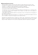
Equipment connection examples Live PA system Electric guitar Drums Drum mics × 8 Vocal/chorus mics × 2 Electric acoustic guitar Keyboard Powered speakers (main) Bass Performer headphones/ speakers × 6 DI Portable audio player Operator headphones 21
BTA-1, for example Computer (for recording and playback) Footswitch 22
Display overview Home Screen ⑥ ⑦⑧ ⑤ ⑫ ① ② ⑬ ⑭ ③ ④ ⑨ No. ⑪ ⑩ Item Explanation 1 Project name This shows the project name. "<" appears if there is another project before this one in the folder. ">" appears if there is another project after this one in the folder. 2 Status icon This shows the status as follows. : Stopped : Paused : Recording : Playing back 3 Counter This shows the hour: minute: second.
Turning the power on and off Turning the power on POWER switch DC IN 12V AC adapter connector GAIN knobs Input and output connectors EFX RTN faders Master fader Channel faders 1. Confirm that the output devices connected to the 24 are turned off.
2. Confirm that is set to OFF. 3. Plug the specified adapter (AD-19) into an outlet. 4. Set all knobs and faders to their minimum values. 5. Connect instruments, mics, speakers and other equipment. HINT Equipment connection example (→ "Equipment connection examples") 6. Set to ON. 7. Turn on the output devices connected to the . NOTE • When using a passive guitar or bass guitar, connect it to channel 1 or 2, and turn on. (→ "Top") • When using a condenser mic, turn on.
Turning the power off 1. Minimize the volume of output devices connected to the 2. Turn off the power of output devices connected to the 3. Set . . to OFF. The following screens appear and the power turns off. NOTE When the power is turned off, the current mixer settings are saved in the project on the SD card. If they cannot be saved to the SD card, they will be saved in the unit.
Using the MENU screen Recorder function settings, for example are made for the nation of the basic menu operations. using the MENU screen. This is an expla- Open the menu: Press This opens the MENU screen. Select menu items and parameters: Turn This moves the cursor. Confirm menu items and parameters: Press This opens the selected MENU screen or parameter setting screen. Return to previous screen: Press This opens the selected MENU screen or parameter setting screen.
Mixer Outputting input sounds from output devices Outputting sound from speakers GAIN knobs MUTE button MUTE buttons Channel faders 1. Use Master fader to adjust the input signals while inputting sound from instruments and mics. NOTE Set them so that SIG indicators do not light red. SIG indicator 2. Turn off (unlit) for the MASTER and the channels with sound you want to output. 3. Set the MASTER fader to 0. 4. Use the channel faders to adjust the volumes. 5.
Outputting sound from headphones SELECT knob VOLUME knob PHONES jack 1. Connect headphones to the PHONES jack. 2. Turn to select the bus you want to output from the PHONES jack, and press The options are MASTER, SOLO and MONITOR OUT A–F. Status Explanation MASTER The same signals as the MASTER OUT are output. A-F The signals set in the FADER MODE section are output. SOLO The signals of SOLO enabled channels are output. 3. Use to adjust the volume. 29 .
Adjusting the tone and panning Channel strip section SEL buttons 1. Press to light it for the channel for which you want to adjust tone and panning. 2. Use the knobs and buttons in the channel strip section to adjust the tone and panning. Adjusting the tone: , , , , Adjusting the panning: Reversing the polarity: NOTE • Press to light it, turning off all equalization at once. This will bypass HIGH, MID, LOW and LOW CUT settings.
Using the built-in effects The has 20 types of send effects in 2 banks. SEND EFX 1/2 knobs EFX1/2 TYPE knobs SEL buttons Parameter knobs 1/2 EFX RTN MUTE buttons EFX1/2 RTN faders 1. Turn / to select the effect type, and press / to confirm. Lit: selected effect type 2. Press to turn it off, unmuting EFX1/EFX2 RTN. 3. Set the EFX1/EFX2 RTN fader to 0. 4. Press for a channel that you want to use the effect on to light it. 5. Use / to adjust the amount for each channel. 6.
Using scene functions The scene function can be used to save up to nine sets of current mixer settings as scenes and to recall these saved settings at any time. ON button RESET button 1–9 buttons RECALL button SAVE button Saving scenes 1. Click so that it lights. This enables the scene function. 2. Press Buttons Press . – will light if they have saved scenes and blink if they do not. again if you do not want to save a scene. 3. Press the button where you want to save the scene.
NOTE • Nine scenes are saved in the unit. (→ "SCENE section") • If a button that already has a scene saved is selected, that scene will be overwritten. • The following items are saved with scenes. - Fader positions (each channel, EFX 1/2 RTN and MASTER) - MUTE ON/OFF (each channel, EFX 1/2 RTN and MASTER) - EQ OFF - LOW CUT - EQ HIGH - EQ MID - EQ MID FREQ - EQ LOW - SEND EFX 1/2 - PAN -Φ - EFX 1/2 TYPE - EFX 1/2 parameters - USB button setting Recalling scenes 1. Click so that it lights.
Resetting mixer settings 1. Click so that it lights. This enables the scene function. 2. Press Buttons Press 3. Press . – will blink if they have saved scenes and be unlit if they do not. again if you do not want to reset the settings. . The current mixer settings are reset to their factory defaults.
Setting signals output from MONITOR OUT A–F The MONITOR OUT A–F jacks can be set to output the same mix as the MASTER OUT or different mixes. MONITOR OUT switches MASTER button Channel faders A–F buttons Adjusting the MONITOR OUT A–F mixes 1. Press an – button to select the output to mix. The selected output button lights and operation of all the channel faders is enabled. NOTE The level meters show the fader positions.
Selecting MONITOR OUT A–F output signals 1. Use the MONITOR OUT switch for an output to select its output signal. To output a mix set using MONITOR OUT A–F: Set the MONITOR OUT switch to A–F ( ) To output the same mix as the MASTER: Set the MONITOR OUT switch to MASTER ( ) Output different mixes for MONITOR OUT A–F Output same mix as MASTER NOTE • Each output mix is saved with the scene and project. • The parameters that can have separate settings for the MASTER and MONITOR OUT A–F are as follows.
Recording and playback Preparing to record Inserting SD cards POWER switch 1. Set SD card slot to OFF. 2. Open the SD card slot cover, and insert an SD card all the way into the slot. To remove an SD card, push it further into the slot and then pull it out. NOTE • Disable write-protection on the SD card before inserting it. • Always set to OFF before inserting or removing an SD card. Inserting or removing a card while the power is on could result in data loss.
Creating new projects The manages recording and playback data in units called projects. 1. Select MENU > PROJECT > NEW PROJECT. 2. Use to select YES, and press . NOTE • See "Projects" for information about projects. • When a new project is created, it will start with the current mixer settings. HINT When the power is turned on, it will automatically load the last used project.
Recording/overdubbing and playing tracks The has recorder functions that enable simultaneous recording of up to 22 tracks and simultaneous playback of up to 20 tracks. The input signals of every channel and from the master fader output can be recorded. These recordings can also be played back. Recording STOP button PLAY/PAUSE button REC button OVER DUB button REC/PLAY buttons 1. Use to turn overdubbing on or off.
5. Press to stop recording. NOTE • The signals recorded on each channel can be set to either before or after the compressor. (→ "Changing the input signal recording source") • Punching in/out (→ "Redoing parts of recordings (punching in/out)") • Starting recording automatically (→ "Recording automatically") • Capturing audio before recording starts (→ "Capturing audio before recording starts") • When recording stops, “Please Wait” appears on the display.
Playing recordings PLAY/PAUSE button STOP button REC/PLAY buttons 1. Press for the channels you want to play, lighting these buttons green. 2. Press to start playback. PLAY/PAUSE indicator Lit: Playing back Blinking: Paused 3. Press to stop playback. NOTE • Playback signals are added before the equalizer section, so their EQ and panning settings can be adjusted during playback.
Adding marks Adding marks at desired positions with the recorder makes moving to those positions easy. Selection encoder FF button REW button Adding marks during recording and playback 1. Press during recording/playback. Moving in mark order 1. Use these buttons to move in mark order. Move to next mark: Press Move to previous mark: Press NOTE Checking and deleting marks in projects (→ "Managing marks") HINT • A maximum of 99 marks can be added to one project.
Redoing parts of recordings (punching in/out) Punching in/out is a function that can be used to rerecord parts of already recorded tracks. "Punching in" is switching track status from playback to recording. "Punching out" is switching track status from recording to playback. With the , punching in/out can be conducted using buttons on its top or a footswitch (ZOOM FS01). STOP button Selection encoder REC button OVER DUB button PLAY/PAUSE button REC/PLAY buttons 1.
Mixing down tracks A final stereo mix can be recorded to the master track. Signals are sent to the master track after passing through the master fader. Mixing down to the master track 1. Click so that it lights. NOTE • Adjust the volume and panning of each recorded track before starting. • When mixing down, set the sampling rate to 44.1kHz or 48kHz. If the sampling rate is 96kHz, the OVER DUB button cannot be set to ON. 2. Press MASTER repeatedly until it lights red. 3.
Playing the master track 1. Press MASTER 2. Press repeatedly until it lights green. . NOTE • To stop master track playback, press MASTER repeatedly until it becomes unlit. • When the master track is playing, other tracks will not be played back. • To listen to master track playback from a MONITOR OUT, set the MONITOR OUT A–F switch to MASTER ( ). • To listen to master track playback from the main headphone jack for the mixer operator, set the SELECT knob to MASTER.
Starting recording automatically Recording can be started and stopped automatically in response to the level after passing through the master fader. Selection encoder MENU button REC button Master fader 1. Select MENU > REC/PLAY > AUTO REC > ON/OFF. 2. Use to select ON, and press . NOTE Making additional settings for automatic recording (→ "Changing automatic recording settings") 3. Press repeatedly to return to the Home Screen.
4. Press . The indicator will light and recording standby will start. The MASTER level meters will blink at the level that will cause automatic recording to start. HINT Recording starts automatically when the input exceeds the set level (shown by the MASTER level meters). You can also set recording to stop automatically when the input goes below a set level. (→ "Setting automatic stopping") 5. Press to end recording standby or stop recording.
Pre-recording before recording starts The input signal can be captured for up to 2 seconds before recording is started (pre-recording). Setting this in advance can be useful when a performance starts suddenly, for example. 1. Select MENU > REC/PLAY > PRE REC. 2. Use to select ON, and press . NOTE • This function cannot be used with the AUTO REC, METRONOME, PRE COUNT or OVER DUB functions. • When you turn AUTO REC or PRE COUNT on, PRE REC will be disabled.
Selecting the folder where projects are saved Choose one of ten folders as the folder where recorded projects will be saved. 1. Select MENU > FOLDER. 2. Use to select the folder where you want to save, and press . NOTE • Up to 1000 projects can be saved in a single folder. • If a folder that does not have a project is selected, a new project will be created automatically.
Selecting projects for playback Projects saved on SD cards can be loaded. 1. Select MENU > PROJECT > SELECT. 2. Use to select the project you want to load, and press . NOTE • Projects in different folders cannot be selected. To select a project that is saved in a different folder, select that folder first. (→ "Selecting the folder where projects are saved") • When a project is loaded, the mixer settings saved in that project are also loaded.
Using the metronome The metronome has adjustable volume, a selectable sound, and a precount function. The volume can also be adjusted separately for each output. Metronome settings are saved separately with each project. Enabling the metronome 1. Select MENU > METRONOME > CLICK. 2. Use to select when the metronome makes sound, and press Setting values . Explanation OFF The metronome does not make sound. REC AND PLAY The metronome sounds during recording and playback.
Changing metronome settings MENU button Selection encoder TEMPO button Changing the metronome tempo 1. Press . The current tempo is shown on the display. 2. Do one of the following to change the tempo.
Setting the precount A metronome count can be sounded before starting recording/playback. 1. Select MENU > METRONOME > PRE COUNT. 2. Use to select the precount behavior, and press Setting values . Explanation OFF No precount will sound. 1–8 Before recording/playback, the precount will sound for the set number of times (1–8). Before recording/playback, the precount will sound as shown below. SPECIAL NOTE • The precount is enabled even during playback.
Changing the metronome sound 1. Select MENU > METRONOME > SOUND. 2. Use to select the sound, and press . HINT The options are BELL, CLICK, STICK, COWBELL and HI-Q. NOTE Press to play the metronome and check the sound. Changing the metronome pattern 1. Select MENU > METRONOME > PATTERN. 2. Use to select the pattern, and press . HINT The options are 1/4–8/4 and 6/8. NOTE Press to play the metronome and check the pattern.
Changing the metronome volume The metronome volume can be adjusted separately for the MASTER OUT and the MONITOR OUT A–F outputs. 1. Select MENU > METRONOME > LEVEL > MASTER or A–F. 2. Turn to adjust the volume, and press . HINT Set from 0 to 100. NOTE Press to play the metronome and check the sound.
Using the slate mic The has a built-in slate mic that is useful for adding comments and talk-back during recording. SLATE button Selection encoder MENU button Recording with the slate mic 1. Start recording. (→ "Recording") 2. Press While to enable the slate mic. is being pressed, the indicator lights and the slate mic is enabled. NOTE • When the slate mic is in use, signals from input jacks are muted to the channels to which the slate mic is routed.
Changing slate mic settings Changing the slate mic volume 1. Select MENU > SLATE > LEVEL. 2. Turn to adjust the volume, and press . Changing the slate mic routing 1. Select MENU > SLATE > ROUTING. 2. Turn to select a channel for routing. 3. Press to confirm. ON OFF ALL: Set routing to all channels at once ALL CLEAR: Clear all settings Channel routing for slate mic input 4. Press . HINT Pressing toggles it ON/OFF.
Projects The manages recording and playback data in units called projects. The following data is saved in projects. • Audio data • Mixer settings • Send return effect settings • Mark information • Metronome settings Changing project names The name of the currently loaded project can be changed. MENU button Selection encoder REC button 1. Select MENU > PROJECT > RENAME. 2. Edit the name.
NOTE • The default project name is the date and time of creation. For example, if a project was created at 6:48:20 p.m. on Wednesday, March 14, 2018, the project name would be "180314_184820" (YYMMDD_HHMMSS). • Project names have 13 characters. • The following characters can be used in project and file names.
Deleting projects Projects inside the selected folder can be deleted. 1. Select MENU > PROJECT > DELETE. 2. Use to select the project you want to delete, and press 3. Use to select YES, and press . NOTE Projects cannot be deleted if protection is ON. 60 .
Protecting projects The currently loaded project can be write-protected, preventing the project from being saved, deleted or having its content changed. 1. Select MENU > PROJECT > PROJECT PROTECT. 2. Use to select ON, and press . NOTE • Projects cannot be used for recording if protection is ON. Turn protection OFF to record. • When protection is OFF for a project, it will always be saved to the SD card when the power is turned off or another project is loaded.
Checking project information Various information about the currently loaded project can be viewed. 1. Select MENU > PROJECT. 2. Use to select INFORMATION, and press .
Saving projects to USB flash drives A USB flash drive can be connected directly to the to it. , and the currently loaded project can be saved MODE switch POWER switch USB HOST port MENU button Selection encoder 1. Set to OFF. 2. Connect the USB flash drive to the USB HOST port. 3. Set 4. Set to USB HOST. to ON. 5. Select MENU > PROJECT > PROJECT EXPORT.
6. Edit the name. Move cursor or change character: Turn Select character to change/confirm change: Press NOTE • The default project name is the date and time of creation. For example, if a project was created at 6:48:20 p.m. on Wednesday, March 14, 2018, the project name would be "180314_184820" (YYMMDD_HHMMSS). • Project names have 13 characters. • The following characters can be used in project and file names.
Importing projects from USB flash drives Projects saved on USB flash drives can be copied to SD cards. NOTE Use a computer to create "ZOOM_L-20" and "PROJECT" folders on the USB flash drive in advance (→ "Saving projects to USB flash drives"). Only projects inside the "PROJECT" folder can be imported. 1. Set to OFF. 2. Connect the USB flash drive to the USB HOST port. 3. Set 4. Set to USB HOST. to ON. 5. Select MENU > PROJECT > PROJECT IMPORT. 6.
NOTE • The default project name is the date and time of creation. For example, if a project was created at 6:48:20 p.m. on Wednesday, March 14, 2018, the project name would be "180314_184820" (YYMMDD_HHMMSS). • Project names have 13 characters. • The following characters can be used in project and file names.
Checking, deleting and moving to marks A list of marks in the currently loaded project can be opened, allowing them to be checked, moved to and deleted. MENU button Selection encoder REC button 1. Select MENU > PROJECT > MARK LIST. A list of marks appears. Indicates added mark E mark indicates time when skipping occurred during recording 2. Turn Press Press to select a mark, and move to or delete it. to move to the mark position. to delete the mark.
Audio files The creates the following types of audio files according to the recording channel. • Channels 1–16: mono WAV files • Channels 17/18, 19/20 and MASTER: stereo WAV files The file format depends on the sampling rate (→ "Changing the sampling rate") and quantization bit depth (→ "Changing the recording format") used by the unit. The can also play back audio files created using DAW software (→ "Importing audio files from USB flash drives").
1. Select MENU > PROJECT > FILE DELETE. 2. Use NOTE Press 3. Press 4. Use to select the file you want to delete, and press . to select/deselect all files. . to select YES, and press . NOTE Audio files cannot be deleted if protection is ON for their projects.
Exporting audio files to USB flash drives The desired audio files can be exported from projects to USB flash drives. Exported audio files will be saved on the USB flash drive in the "AUDIO" subfolder of the "ZOOM_L-20" folder. MENU button Selection encoder REC button 1. Set to OFF. 2. Connect the USB flash drive to the USB HOST port. 3. Set 4. Set to USB HOST. to ON. 5. Select MENU > PROJECT > FILE EXPORT.
6. Use to select a file you want to export, and press . 7. Edit the name. Move cursor or change character: Turn Select character to change/confirm change: Press NOTE • Audio file names have 24 characters. • The following characters can be used in project and file names. (space) ! # $ % & ' ( ) + , - 0 1 2 3 4 5 6 7 8 9 ; = @ A B C D E F G H I J K L M N O P Q R ST U V W XY Z [ ] ^ _ ` abcdefghijklmnopqrstuvwxyz{~} • Project/file names cannot be only spaces. 8. Press 9. Use .
Importing audio files from USB flash drives The desired audio files can be imported from USB flash drives to existing projects and assigned to channels. NOTE Use a computer to create "ZOOM_L-20" and "AUDIO" folders on the USB flash drive in advance (→ "Saving projects to USB flash drives"). Only audio files inside the "AUDIO" folder can be imported. 1. Set to OFF. 2. Connect the USB flash drive to the USB HOST port. 3. Set 4. Set to USB HOST. to ON. 5. Select MENU > PROJECT > FILE IMPORT. 6.
NOTE • Mono WAV files can be assigned to mono channels and stereo WAV files can be assigned to stereo channels. • Files cannot be imported to channels that already have files assigned to them. • When files are imported, their file names will automatically be changed according to their import channels. 8. Use to select YES, and press . NOTE Never disconnect a USB flash drive when “Please Wait ...” appears on the display.
Using audio interface functions The can be used as a 22-in/4-out USB audio interface. After applying its compressor, each input channel always outputs its signal to the corresponding USB audio channel. Channels 1–20 and the stereo signal output from the master fader are sent to the computer (22 channels total). Installing the driver 1. Download the "ZOOM L-20 Driver" from http://www.zoom.co.jp to the computer. NOTE • You can download the latest "ZOOM L-20 Driver" from the above website.
Connecting to a computer USB DEVICE port MODE switch POWER switch 1. Use a USB cable to connect the USB DEVICE port to the computer. 2. Set the 3. Set switch to AUDIO INTERFACE. to ON. NOTE • Set to ON when connected to an iOS device. • When connecting to an iOS device, use a Lightning to USB camera adapter (or Lightning to USB 3 camera adapter). 4. Set the as the computer sound device. NOTE • Audio interface functions cannot be used when the sampling rate is set to 96 kHz.
Inputting return signals from the computer to a stereo channel USB buttons 1. Turn / ON for the stereo channel to use for input. The signal controlled by the channel is switched to the USB audio channel signal (before EQ).
Using card reader functions When connected to a computer, data on the SD card can be checked and copied. USB DEVICE port POWER switch MODE switch 1. Use a USB cable to connect the USB DEVICE port to the computer. 2. Set 3. Set to CARD READER. to ON. NOTE When operating as a CARD READER, other functions and buttons cannot be used.
Recording and playback settings Changing the recording format The recording format can be changed in consideration of audio quality and file size. 1. Open MENU > REC/PLAY > REC FORMAT. 2. Use to change the format, and press . HINT When overwriting a recording, recording will occur at the bit depth of the original file. For example, a file recorded at 16-bit cannot be overwritten with 24-bit recording.
Changing automatic recording settings The conditions for automatically starting and stopping recording can be set. Setting the automatic recording start level 1. Open MENU > REC/PLAY > AUTO REC > REC START LEVEL. 2. Use to change the start level, and press . Recording will start automatically when the level of the MASTER fader output signal exceeds the set level. HINT This can be set from −48 to 0 dB.
Setting automatic stopping 1. Open MENU > REC/PLAY > AUTO REC > AUTO STOP. 2. Use to select the automatic stop time, and press . HINT This can be set to OFF or between 0 and 5 seconds. 3. Open MENU > REC/PLAY > AUTO REC > REC STOP LEVEL. 4. Use to set the stop level, and press . Recording will stop automatically when the level of the MASTER fader output stays below the set level for the amount of time set in step 2.
Showing recording levels on level meters The levels of signals recorded to the recorder can be shown on the level meters of each channel. 1. Open MENU > REC/PLAY > REC LEVEL METER. 2. Use to select ON, and press . If recorded signal levels are higher than post fader levels, the recorded signal levels are shown lit dimly on the level meters.
Compensating for latency that occurs during input and output The can compensate for latency that occurs during input and output if you want to listen to its output signal while overdubbing. Use this menu item to set whether the latency that occurs during input and output is automatically compensated for or not when OVER DUB is ON. When automatic compensation is enabled, the recording data is shifted by the amount of latency that occurs during input and output.
Changing the playback mode 1. Open MENU > REC/PLAY > PLAY MODE. 2. Use to select the play mode, and press . Setting values Explanation OFF Only the selected project plays back. Playback continues even when the end of a file is reached. PLAY ONE (single song playback) Only the selected project plays back. Playback stops when the end of a file is reached. PLAY ALL (all playback) Every project from the selected one to the last one will be played back.
SD card settings Checking the open space on SD cards 1. Open MENU > SD CARD > REMAIN. This shows the open space on the card. NOTE The shows less than the actual open space in order to maintain space to prevent SD card writing performance from degrading. Formatting SD cards Format SD cards for use with the . 1. Open MENU > SD CARD > FORMAT. 2. Use to select YES, and press .
Testing SD card performance You can test whether SD cards can be used with the . A basic test can be done quickly, while a full test examines the entire SD card. Conducting a quick test 1. Open MENU > SD CARD > PERFORMANCE TEST. 2. Turn to select QUICK TEST, and press 3. Use to select YES, and press . . The card performance test will start. The test should take about 30 seconds. The result of the test will be shown when it completes.
4. Press to stop the test. NOTE Even if a performance test result is "OK", there is no guarantee that writing errors will not occur. This information is just to provide guidance. Conducting a full test 1. Open MENU > SD CARD > PERFORMANCE TEST. 2. Use to select FULL TEST, and press . The amount of time required will be shown. 3. Use to select YES, and press . The result of the test will be shown when it completes. If the access rate MAX reaches 100%, the card will fail (NG).
4. Press to stop the test. HINT You can press to pause and resume a test. NOTE Even if a performance test result is "OK", there is no guarantee that writing errors will not occur. This information is just to provide guidance.
Making various settings Setting the date and time Display MENU button REC button 1. Select MENU > SYSTEM > DATE/TIME. 2. Setting the date and time Move cursor or change value: Turn Select item/confirm change: Press 3. Press . The first time you turn the power on after purchase, you must set the date/time.
Setting the footswitch If a footswitch (ZOOM FS01) is connected to the CONTROL IN jack, you can start/stop recorder playback punch in/out or mute/unmute the send effect by foot. 1. Open MENU > SYSTEM > CONTROL IN. 2. Turn to select the setting value, and press . Setting values Explanation PLAY Press the footswitch to start/stop playback. (Equivalent to PUNCH I/O Use to control manual punching in/out. (Equivalent to EFX1 MUTE Mute/unmute send effect 1. EFX2 MUTE Mute/unmute send effect 2.
Changing the sampling rate The file format used when recording to the recorder depends on this setting. Before changing the sampling rate, 1. Confirm that 2. Change the must be set to OFF. is set to OFF. position. HINT This can be set to 44.1 kHz, 48 kHz or 96 kHz. NOTE • Format an SD card before recording to it at 96 kHz. If you record without formatting first, skipping could occur. • When 96 kHz is selected, some unit operations are limited. The limited functions are as follows.
Disabling the automatic power saving function The power will automatically turn off if the is unused for 10 hours. If you want the power to stay on always, disable the automatic power saving function. 1. While pressing and holding 2. Use to select OFF, and press , set to ON. . NOTE This setting is saved in the unit. Adjusting the display contrast 1. Open MENU > SYSTEM > DISPLAY CONTRAST. 2. Turn to select the setting value, and press . HINT This can be set from 1 to 10.
Restoring settings to factory defaults You can restore the factory default settings. 1. Open MENU > SYSTEM > FACTORY RESET. 2. Use to select YES, and press . NOTE This does not reset mixer settings.
Checking the firmware versions. The firmware versions can be viewed. 1. Open MENU > SYSTEM > FIRMWARE VERSION. This shows the firmware versions.
Updating the firmware The firmware can be updated to the latest versions. 1. Copy the firmware update file to the root directory on an SD card. NOTE Files for the latest firmware updates can be downloaded from the ZOOM website (www.zoom.co.jp). 2. Insert the SD card into the 3. While pressing 4. Press , set . to ON. . NOTE During the firmware update, do not turn the power off or remove the SD card. Doing so could cause the to become unstartable. 5.
Control from an iPad By connecting a BTA-1 or other ZOOM-specific wireless adapter (sold separately) and using the dedicated controller app, the can be operated from an iPad. NOTE • Before turning the on, connect the BTA-1 or other ZOOM-specific wireless adapter (sold separately). • Download the dedicated app from the App Store. Connecting with an iPad Pairing beforehand is necessary to connect with an iPad. 1. While the 2.
Troubleshooting General There is no sound or output is very quiet • Check the speaker connections and volume settings on the speakers. • Check instrument and mic connections. • When using a condenser mic, turn on. • Confirm that the SIG indicators are lit green. • Confirm that is unlit. • Raise all the channel faders and the master fader, and confirm that the level meters are lit. • Confirm that the MASTER is unlit or lit red.
The sounds of devices connected to input jacks are distorted • Confirm that the SIG indicators are not lighting red. If they are lighting, lower their input gains. You can also turn on. • Confirm that level meters are not lighting to their highest levels. If a level meter is lighting to its highest level, lower its fader. A send effect is not working • Confirm that the EFX 1/2 RTN is unlit. • Raise the EFX 1/2 RTN fader, and confirm that the EFX 1/2 RTN level meters are lit.
Specifications Number of input Inputs and output channels Outputs Mono (MIC/LINE) Stereo (LINE) MASTER OUT MONITOR OUT PHONES Type Input gain Inputs Mono (MIC/LINE) Outputs Input impedance Maximum input level Phantom power Stereo (LINE) Type Maximum input level MASTER OUT Type Maximum output level Output impedance MONITOR OUT A–F Type (with balanced output) Maximum output level connected to monitor Output impedance speakers Buses Channel strip 16 2 1 6 1 XLR/TRS combo jacks (XLR: 2 HOT, TRS: TIP HOT
Send effect specifications EFX 1 Parameter knob 1 Parameter knob 2 Hall reverb with a bright tone TONE DECAY Hall reverb with a long time for early reflections TONE DECAY Dense room reverb TONE DECAY Plate reverb simulation TONE DECAY Reverb that simulates the sound of a church TONE DECAY Reverb that adds a natural ambience (air sound) to drums TONE DECAY Special reverb suited to percussive performances TONE DECAY Vocal 1 Very useful effect that combines delay with hall reverb TIME
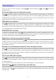
Hi-Z PAD -26dB GAIN A/D A/D Metronome Built-in Mic INPUT 17/18 – 19/20 PC OUT 1/3 PC OUT 2/4 PLAY DATA 17/18 PLAY DATA 19/20 INPUT 1-16 PLAY DATA 1-16 (INPUT 1/2) (INPUT 3-16) AD DC CUT DC CUT GAIN USB SIG SLATE REC SOURCE SLATE REC/PLAY SLATE REC LEVEL METER COMP REC/PLAY REC/PLAY REC SOURCE LOW CUT PHASE LOW CUT REC DATA 17/19 to SD CARD REC DATA 18/20 to SD CARD USB SEND DATA 17/19 to PC USB SEND DATA 18/20 to PC PHASE USB SEND DATA 1-16 to PC REC DATA 1-16 to SD CARD E
ZOOM CORPORATION 4-4-3 Kanda-surugadai, Chiyoda-ku, Tokyo 101-0062 Japan http://www.zoom.co.