
Operation Manual
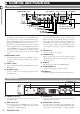

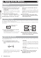


Front Panel
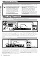
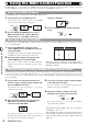
Rear Panel
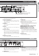
(17) BANK LEDs
(18) EFFECT TYPE selector and LED
(19) REV CHARACTER (EDIT 1) control and LED
(20) REV TIME (EDIT 2) control and LED
(21) REV EQ LOW (EDIT 3) control and LED
(22) REV EQ HIGH (EDIT 4) control and LED
(23) POWER switch
(4) DIGITAL OUT connectors
(5) OUTPUT jacks (6) INPUT jacks
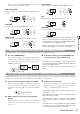
(11) Level meter
These indicators show the signal input level.
(12) VALUE UP/DOWN keys
Serve for switching patches and changing parameter
values. Holding down one key while pressing the other
results in a fast change.
(13) BANK key
Serves to select the effect bank (group of effects arranged
by general type).
(14) Display
Shows various information such as patch numbers and
parameter values.
(15) TAP key and LED
This key serves for tap input of time-based parameters
such as delay time and rate. When an effect where tap
input can be used is selected, the LED flashes with a
frequency that indicates the current setting. When an
effect where tap input cannot be used is selected, the LED
is out.
(16) BYPASS key and LED
Serves to set the unit to the bypass condition where only
the original sound is output. In this condition, the LED is
lit.
(17) BANK LEDs
These indicators show which bank is currently selected.
(18) EFFECT TYPE selector and LED
Serves to choose an effect from the currently selected
bank. If the setting was changed since the last store
operation, the LED lights up.
(19) REV CHARACTER (EDIT 1) control and LED
(20) REV TIME (EDIT 2) control and LED
(21) REV EQ LOW (EDIT 3) control and LED
(22) REV EQ HIGH (EDIT 4) control and LED
These controls allow the user to adjust effect parameters
to a desired value. Which parameters can be adjusted
depends on the currently selected effect. If a setting was
changed since the last store operation, the respective LED
lights up.
(23) POWER switch
Serves to turn the unit on and off.
with a digital input, such as a digital multitrack recorder,
MD recorder, or DAT recorder. The optical and coaxial
output connectors can be used at the same time. The
OUTPUT control is not active in this case.
(5) OUTPUT jacks
Connect these jacks to the recorder or playback system.
(6) INPUT jacks
Connect a line-level source, such as an instrument or CD
player to these jacks. If a plug is inserted only in the
L/MONO jack, the signal from this plug will be supplied
to both channels.
Controls and Functions
Controls and Functions
ZOOM RFX-2200
3