
User's Manual ADSL Modem X5

8
X5
ADSL Modem User’s Manual
2
22
2
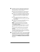
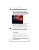
All hardware connections originate from the modem’s back
panel. (For reference, we have included a table that defines
these back panel ports, or jacks; see page 41.)
a
aa
a
Plug one end of the supplied phone cord into the unit’s
DSL
jack and the other end into the ADSL wall jack.
b
bb
b
Plug one end of the straight-through Ethernet (10BaseT)
cable into one of the modem’s LAN jacks (
1
,
2
,
3
, or
4
)
and plug the other end into your computer’s Ethernet
port.
c
cc
c
Plug one end of the included power adapter into the
unit’s
POWER
jack and the other end into a power strip
or wall receptacle.
d
dd
d
Turn the unit on by pushing the
ON/OFF
switch. The
PWR
light on the unit’s front panel turns on.
Note: You can also attach the X5 to an access point,
switch, or network hub via its LAN jack(s) and thereby
connect additional computers.
—
If your hub has an uplink or daisy chain port, you can use
the supplied straight-through Ethernet cable to connect the
two.
—
If your hub has a numbered port or if you are using an
access point, you need a crossover Ethernet cable (sold
separately).
Throughout this manual, when we refer to an X5 Ethernet
connection, it should be understood that this connection may
be to a computer, access point, or hub.
3
33
3
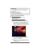
The unit performs a startup sequence—the front panel
LINK
light blinks. (For reference, we have included a table on page
42 that defines the X5’s front panel lights.) When the
LINK
light changes from blinking to solid, turn your computer back
on and proceed to
Establishing Communication with the
X5
(page 10).