
Installation Guide

ഌ
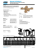
Flow Characteristics
Zurn Industries, LLC
| Wilkins
1747 Commerce Way, Paso Robles, CA U.S.A. 93446 Ph. 855-663-9876, Fax 805-238-5766
In Canada | Zurn Industries Limited
3544 Nashua Drive, Mississauga, Ontario L4V 1L2 Ph. 905-405-8272, Fax 905-405-1292
www.zurn.com
Page 2 of 2
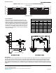
Typical Installation
Local codes shall govern installation requirements. To be
installed in accordance with the manufacturers’ instructions
and the latest edition of the Uniform Plumbing Code. Unless
otherwise specified, the assembly shall be mounted at a mini-
mum of 12” (305mm) and a maximum of 30” (762mm) above
adequate drains with sufficient side clearance for testing and
maintenance. The installation shall be made so that no part
of the unit can be submerged or where relief valve discharge
could cause damage.
Speci cations
The Reduced Pressure Principle Backflow Preventer shall be ASSE® 1013 Listed, rated to 180° F and supplied with full port
union ball valves. The main body and access covers shall be bronze (ASTM B 584), the seat ring and all internal polymers
shall be NSF® Listed Noryl™ and the seat disc elastomers shall be silicone. The first check shall be accessible for mainte-
nance without removing the relief valve. If installed indoors, the installation shall be supplied with integral monitor switch and
air gap piped to a properly sized drain. The Reduced Pressure Principle Backflow Preventer shall be a ZURN WILKINS Model
975XLU.
AIR GAP
12" MIN.
30" MAX.
DIRECTION OF FLOW
DRAIN
PROTECTIVE
ENCLOSURE
12" MIN.
30" MAX.
DIRECTION OF FLOW
0
20
40
60
80
5
10
15
20
0
50
100
150
200
250
5
10
15
20
FLOW RATES (GPM)
PRESSURE LOSS (PSIG)
69
PRESSURE LOSS (kpa)
FLOW RATES (l/s)
MODEL 975XLU 3/4", 1", 1 1/4", 1 1/2" & 2" (STANDARD & METRIC)
35
3/4" (20mm)
1" (25mm)
1 1/4" (32mm)
2" (50mm)
103
15.8
12.6
9.5
6.3
3.2
5.0
3.82.52
1.26
11/2"
(40mm)
137