
Install Instructions

Model 600XL LEAD-FREE*
Pressure Reducing Valve with Integral By-pass
(1/2”, 3/4”, 1”, 1 1/4”, 1 1/2” & 2”)
*This product contains a weighted average lead content less than 0.25% for wetted surfaces.
Installation Testing Maintenance Instructions
Proposition 65 Warning This product contains chemicals known to the State of California to cause
cancer or birth defects or other reproductive harm.
1
®
WARRANTY: ZURN WILKINS Valves are guaranteed against defects of material or workmanship when used for the services recom-
mended. If in any recommended service, a defect develops due to material or workmanship, and the device is returned, freight prepaid,
to ZURN WILKINS within 12 months from date of purchase, it will be repaired or replaced free of charge. ZURN WILKINS’ liability shall
be limited to our agreement to repair or replace the valve only.
Regulators in series: Where the desired pressure reduction is
more than a 4 to 1 ratio (i.e. 200psi to 50psi), multiple regulators
in series should be installed.
SEALED CAGE WARNING: Loosen lock washer at adjustment
bolt slowly. Look for any trapped water pressure under the sealed
cage washer. Relieve pressure before removing bell.
CAUTION: Anytime a reducing valve is adjusted, a pressure gauge
must be used downstream to verify correct pressure setting. Do
not bottom out adjustment bolt on bell housing. Valve may be
installed in any position.
REPAIR KIT INSTRUCTIONS
HOW TO MAKE REPAIRS:
(Shut off service before starting disassembly)
1. Open faucet on dwelling to remove line pressure.
2. Note distance that adjustment bolt protrudes from bell housing.
Loosen locknut on adjustment bolt, then turn adjustment bolt out
of bell housing until free of spring tension.
3. Loosen main cap and remove counterclockwise.
4. Loosen plunger and remove counterclockwise. Remove old seal
ring then insert new seal ring.
5. Loosen strainer cap counterclockwise and remove screen.
6. Unscrew bell housing counterclockwise and remove spring,
spring disc and friction ring.
7. Remove stem assembly from regulator. Inspect area in body
where stem o-ring guides for pitting or scratches. Smooth bore with
emery cloth if needed. This area must be smooth for the valve
to function correctly.
TO REASSEMBLE:
1. Openshut-offvalveslowlyandushbodyandlineofanydebris.
2. Assemble new stem unit using new stem, o-ring, diaphragm,
diaphragm disc and diaphragm bolt/nut. Tighten bolt/nut securely
(CAUTION: Be sure the rounded edge of the diaphragm disc is next
to the diaphragm).
3. Lubricate o-ring with grease supplied in repair kit and install
stem unit in body.
4. Center washer on stem. Screw plunger into stem unit.
CAUTION: Do not over tighten plunger; it is possible to break
the threaded end of the plunger.
5. Install new spring, spring disc and friction ring then replace
bell housing by tightening clockwise. Turn adjustment bolt
clockwise until adjustment bolt touches spring disc.
6. Install new screen, cap gaskets and replace caps by tightening
clockwise.
7. Turn adjustment bolt into bell housing to old setting then enter
dwelling and turn on several faucets.
8. Turn on water service. Let water run for several seconds then
turn off faucets in dwelling.
9. Adjust the regulator to desired pressure by turning adjustment bolt
clockwise (into bell housing) to raise pressure or counterclockwise
(out of bell housing) to lower pressure. It is recommended a
pressure gauge be installed downstream of the regulator to
ensure pressure is reduced below 75 psi. NOTE: When reducing
pressure, open a downstream faucet to relieve pressure.
10.Tighten locknut when desired pressure is achieved.
INSTALLATION INSTRUCTIONS
Install valve in line with arrow on valve body pointing in direction of
ow.Beforeinstallingreducingvalve,ushoutlinetoremoveloose
dirt and scale which might damage seal ring and seat. All valves will be
furnished with stock settings to reduce to 50 psi. To readjust reduced
pressure, loosen outer locknut and turn adjustment bolt clockwise (into
bell housing) to raise reduced pressure, or counterclockwise (out of
bell housing) to lower reduced pressure.
NOTICE: Annual inspection and maintenance is required of all
plumbing system components. To ensure proper performance
and maximum life, this product must be subject to regular inspec-
tion, testing and cleaning.
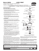
CAP GASKET*
SEAT
*WASHER
*O-RING
PLUNGER
SEAL RING*
STRAINER CAP
UNION NUT
*SPRING DISC
TAILPIECE
UNION
GASKET*
STEM*
*DIAPHRAGM
DIAPHRAGM DISC*
SPRING*
FRICTION RING*
(1/2"-1 1/2" only)
NAMEPLATE
600XL
MAIN CAP
LOCKNUT
BELL HOUSING
CAP GASKET*
SCREEN*
BODY
SEAT GASKET
* INDICATES PARTS SUPPLIED IN REPAIR KITS
(spring disc not included in sizes 1 1/2"-2")
ADJUSTMENT
BOLT
SEALED CAGE
WASHER
*DIAPHRAGM
NUT/BOLT
IN
®