
Installation Guide
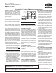

Model 950XL
Double Check Valve Assembly (3/4"-2")
Model 975XL
Reduced Pressure Principle Assembly (1/4"-2")
CAUTION: Installation of Backow Pre-
venters must be performed by qualied,
licensed personnel. The installer should
be sure the proper device has been se-
lected for the particular installation. Faulty
installation could result in an improperly
functioning device.
ZURN WILKINS Model 975XL Reduced
Pressure Principle Backow Preventers
are for use on water lines where a health
hazard could exist if a backow situation
were to occur.
ZURN WILKINS Model 950XL Double
Check Valve assemblies are for use on
water lines where a health hazard does not
exist in the event of a backow situation.
Proper performance is dependent upon
following these installation instructions and
prevailing governmental and industry stan-
dards and codes. Failure to do so, accord-
ing to ZURN WILKINS Limited Warranty "...
releases ZURN WILKINS of any liability that
it might otherwise have with respect to that
device." Such failure could also result in an
improperly functioning device.
Damage to the device could result wherever
water hammer and/or water thermal expan-
sion could create excessive line pressure.
Where this could occur, shock arresters
and/or pressure relief valves should be
installed downstream of the device.
1. Before installing either a Model 975XL or
Model 950XL Backow Preventer, ush
the line thoroughly to remove all debris,
chips and other foreign matter. If required,
a strainer should be placed upstream of
the Backow Preventer. CAUTION: Do
not use a strainer in seldom used emer-
gency waterlines such as re lines.
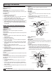
2. The Model 975XL must be installed in
a horizontal position to provide proper
operation of the relief valve.
3. Provide adequate space around the
installed unit so that the test cocks will
be accessible for testing and servicing.
4. If installation of a Model 975XL is in a
building, provide a suitable drain ar-
rangement to drain off spillage from the
relief valve. An air gap at least two times
the pipe diameter must be provided
between the relief valve and the drain
piping to prevent a cross-connection.
CAUTION: Do not pipe the relief valve
solidly to a oor drain, sewer or sump.
5. Install valve at least 12 inches above
surrounding ood level.
6. Always consult local codes for installa-
tion methods, approvals and guidance.
OUTDOOR INSTALLATION
Model 975XL and Model 950XL Backow
Preventers may be installed outdoors only
if the device is protected against freezing
conditions. Exposure to freezing conditions
will result in improper function or damage
to the device. The installation location must
be kept above 32°F. All the basic installation
instructions apply.
If installation is in a pit or vault, the Backow
Preventer must never be submerged in
water because this could cause a cross-
connection. Make sure that the pit or vault
always remains dry by providing ample
drainage.
INDOOR INSTALLATION
Indoor installation is preferred in areas that
are subject to freezing conditions. All the
basic installation instructions apply to such
installations.
PARALLEL INSTALLATION
Where uninterrupted service from a single
meter connection must be maintained, two
or more Backow Preventers may be con-
nected in parallel. All the basic installation
instructions apply to parallel installation. Be
sure to allow adequate room between the
units for testing and repair.
PLACING THE DEVICE IN SERVICE
After the installation of a Model 975XL or
Model 950XL has been completed, place
the unit in service as follows:
975XL REDUCED PRESSURE PRINCIPLE
1. Start with both shut-off valves closed.
Slowly open the inlet shut-off valve un-
til the backow preventer is completely
pressurized. A brief discharge from
the relief valve may occur while the
device is pressurizing. The discharge
should cease by the time the shut-
off valve is fully open. Device should
function properly. If the discharge does
not stop, refer to "MAINTENANCE IN-
STRUCTIONS" for repair procedures.
2. After the device has been pressurized,
vent all trapped air from both check
valve by slightly opening each of the
four test cocks.
3. Slowly open the downstream shut-off
valve. The Model 975XL Reduced
Pressure Principle Backow Preventer
is now in service.
4. If "spitting" or intermittent discharges
from the relief valve are noted, it could
be a result of pressure uctuation and/
or a water hammer condition in the sys-
tem. If such conditions exist, install wa-
ter pressure reducing valves or water
hammer shock arresters in compliance
with industry standards as needed.
5. After the Model 975XL has been
properly installed, test the device (see
"TEST PROCEDURES"). If the device
fails the test, remove the rst and
second check valves and thoroughly
ush the device. If the relief valve fails
to operate properly, inspect the sensing
passage for clogging (see "MAINTE-
NANCE INSTRUCTIONS"). Clean
rubber seals of all debris and place unit
back in service.
950XL DOUBLE CHECK VALVE ASSEMBLY
1. Start with both shut-off valves closed.
Slowly open the inlet shut-off valve un-
til the backow preventer is completely
pressurized.
2. When the unit has been pressurized,
vent any trapped air by slightly opening
each of the four test cocks.
3. Slowly open the downstream shut-off
valve. The Model 950XL Double Check
Valve assembly is now in service.
4. After the Model 950XL has been
properly installed, test the device (see
"TEST PROCEDURES"). If the device
fails the test, remove the rst and sec-
ond check valves and thoroughly ush
the device. Clean rubber seats of all
debris and place unit back in service.
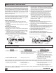
12" MIN
30" MAX
PROTECTIVE
ENCLOSURE
OPTIONAL
WATER METER
INLET SHUT-OFF
AIR GAP
DRAIN
DIRECTION OF FLOW
®
WARNING: This product is NOT Lead Free in accordance with U.S. Federal Law and is illegal in the U.S. for use in potable services or to
install in water systems anticipated for human consumption.
! WARNING: Cancer and Reproductive Harm - www.P65Warnings.ca.gov
! ADVERTENCIA: Cáncer y daño reproductivo - www.P65Warnings.ca.gov
! AVERTISSEMENT: Cancer et néfastes sur la reproduction - www.P65Warnings.ca.gov
Installation Testing Maintenance Instructions