
Installation Guide
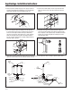
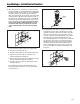


4. Determine the length of vacuum breaker tube required to
join the flush valve and fixture spud. Cut the vacuum breaker
tube, if required, to this length (see 4a). As sem ble the vacuum
breaker tube assembly and spud nut as sem bly to the flush
valve and fixture spud.
4a
1
2
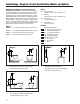
1. Install stop valve assembly using proper size supply es cutch eon
and sweat solder adapter kit if applicable (see 1). Thread sealing
compounds should be used on male NPT threads only.
2. Prior to inserting the flush valve tailpiece into the stop valve,
be certain that the O-ring seal is located in O-ring seal groove
at the end of the tailpiece and the locking nut and locking
snap ring are located as shown below (see 2). Care should be
taken not to damage the O-ring when inserting the tailpiece
into the stop valve. If lubrication is needed, wetting the O-ring
with water will be sufficient.
5
5. Hand tighten spud nut and vacuum breaker tube nut to fixture and flush valve. Adjust the valve assembly for plumb. Tighten fixture
spud nut, vacuum breaker tube nut, and lock nut with a wrench.
3
3. Insert the flush valve tailpiece into the stop valve and hand
tighten the lock nut to the stop valve. Plumb the entire unit
(see 3).
4b
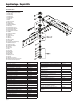
AquaVantage
®
Installation Instructions
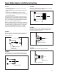
FIBER
WASHER
RUBBER
GASKET
SPUD NUT
FIXTURE
ESCUTCHEON
3/4"
VACUUM
BREAKER
TUBE
TUBE NUT
FIBER
WASHER
1-1/4"
VACUUM
BREAKER
TUBE
FIBER
WASHER
1-1/2"
VACUUM
BREAKER
TUBE
1-1/2"
VACUUM
BREAKER
TUBE
TUBE NUT
COUPLING NUT
FIBER WASHER
RUBBER GASKET
ELBOW
COUPLING NUT
HORIZONTAL TUBE
FIBER WASHER
RUBBER WASHER
RUBBER WASHER
FIBER WASHER
SPUD NUT
FIXTURE
ESCUTCHEON
Page 4