
Installation Guide

FV254 Rev. E 12/9/2014
Page 2
IMPORTANT:
• ALL PLUMBING IS TO BE INSTALLED IN ACCORDANCE
WITH APPLICABLE CODES AND REGULATIONS.
• FLUSH ALL WATER LINES PRIOR TO INSTALLATION.
• SENSOR UNITS SHOULD NOT BE LOCATED ACROSS FROM
EACH OTHER OR IN CLOSE PROXIMITY TO HIGHLY REFLEC-
TIVE SURFACES.
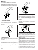
1. - Cover Plate Installation
(For faucets with -CP4 or -CP8 suffix)
Remove adhesive backing from gasket and then pass sensor
connector wire and shank through gasket. Align gasket with fau-
cet bottom and press firmly together. Pass sensor connector and
shank through cover plate and fasten to the faucet with the pro-
vided screws.
3.- Electronics Module Installation
Attach sensor connector wire from the faucet to the mating sensor
connector wire from the eletronics module. Orient connectors so
that the pins are properly aligned before pressing connectors
together. Do not force together, damage to pins may occur.
Secure the cable connectors with the locking ring provided. Be
certain that the cable connection is made before the batteries
are installed.
Attach electronics module to the shank using the hex nut and
gasket provided. Orient the electronics in a convenient location
and tighten hex nut.
DO NOT USE THREAD SEALANT.
2.- Spout Installation
If there is an exsisting faucet, turn off water supply and remove the
old faucet. Assure supply lines are completely flushed and free of
debris. Clean lavatory rim around the mounting area for the new
sensor faucet.
Place the sensor connector wire and shank through cover plate
gasket and hole in the lavatory. Orient black plastic mounting
washer with the slot facing up. Place mounting washer and star
washer over shank and secure the entire assembly to the lavatory
with the mounting nut. The sensor wires must pass through slot
in plastic mounting washer. *Do not pinch Sensor wires.
4a.- Battery Installation
Loosen the battery cover screw with the supplied allen wrench.
Remove the cover and install the batteries as indicated on the
battery case. Replace the battery cover and secure.
4b.- ACA Plug-In Adapter Installation
When using the -ACA plug-in power supply remove sticker at loca-
tion (A) and plug in adapter.
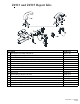
5.- Filter or Mixing Tee or Mixing Valve Installa-
tion
The supplied inlet filter must be used with every faucet, unless a
mixing tee or mixing valve is ordered. The inlet filter is attached
directly to the electronics module’s water inlet. Tempered water
is then supplied to the filter using a standard 3/8” x 1/2” ball riser
(supplied by others.)
The optional mixing tee assembly (-MT) or mixing valve (-MV) have
integral filters and back checks. These take the place of the stan-
dard inlet filter when ordered. The mixing tee or mixing valve
outlet attaches to the electronics module with a 3/8” x 1/2” ball
riser (supplied by others). Hot and cold water is then supplied to
the appropriate 3/8” compression inlets.