
Install Instructions


FV343 Rev N 4/16/10
Page 4
COURTESY
FLUSH SW ITCH
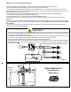
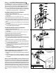
STEP 7 - Valve Installation (Figure 7)
Install valve to control stop with the bottom of the valve tilted
slightly up towards you and leave the valve nut loose. Make
sure not to damage o-ring on valve. Make sure vacuum breaker
and vacuum breaker disc are properly installed within the flush
tube. Rotate valve down over vacuum breaker tube and tighten
tube nut to valve. After tube nut is tight, tighten valve nut to
control stop.
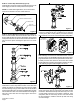
STEP 9 - Actuator Installation (Figure 9)
Slide wall flange over the chrome cover tube as shown. Connect
the plug connector on the ZEMS-IS actuator with the DC power
plug located within the access hole just behind the flush valve.
Carefully tuck the wires back into the access hole. Install
handle gasket into actuator nut and tighten actuator to valve.
Push wall flange against wall and tighten set screw.
Figure 7
Figure 9
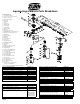
SUPPLY FLANGE W / SET SCREW
CHROME TUBE COVER
SW EAT SOLDER ADAPTER
CONTROL STOP
STOP CAP
SCREW COVER
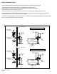
STEP 6 - Vacuum Breaker Flush Connection (Figure 6)
Place vacuum breaker and vacuum breaker disc in tube as
shown. Slide the tube nut, spud nut, slip washer, rubber gasket
and spud escutcheon over the vacuum breaker tube and insert
tube into fixture spud. Hand tighten spud nut on to fixture
spud.
STEP 5 - Control Stop Installation (Figure 5)
Install the Zurn control stop valve and wall escutcheon to the
water supply line with the outlet positioned as required.
NOTE:For sweat solder applications, see recommended
instructions included in the Zurn sweat solder kit.
Figure 5
Figure 6
STEP 10 - Flush Out Supply Line (Figure 9)
Close control stop. Remove valve body cover and lift out trip
mechanism. Reinstall internal cap and valve body cover. Turn
on water supply to flush line of any debris or sediment. After
completion, shut off control stop, remove cover and reinstall
the trip mechanism. Install the internal cap and valve body
cover wrench tight.
STEP 8 - Courtesy Flush Option (Figure 8)
Product is configured at time of shipment for a 168 hour
courtesy flush. (SW 1 in OFF position.) If a 48 hour courtesy
flush is desired, remove rear cover and set SW 1 to ON position.
Figure 8