
Use and Care Manual

FV237 Rev. F 6/25/2018
Page 2
PRIOR TO INSTALLATION
Prior to installing the ZER Flushometer, install the
items listed below:
• Closet or urinal xture
• Drain line
• Water supply line
IMPORTANT:
• ALL PLUMBING IS TO BE INSTALLED IN ACCORDANCE WITH
APPLICABLE CODES AND REGULATIONS.
• WATER SUPPLY LINES MUST BE SIZED TO PROVIDE AN
ADEQUATE VOLUME OF WATER FOR EACH FIXTURE.
• FLUSH ALL WATER LINES PRIOR TO OPERATION (See
Step 9).
• DIRT AND DEBRIS CAN CAUSE FLUSH VALVE TO RUN
CONTINUOUSLY.
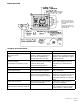
The ZER is designed to operate with 20 to 80 psi (138 to 552 kPa) of water pressure. THE MINIMUM PRESSURE REQUIRED TO
THE VALVE IS DETERMINED BY THE TYPE OF FIXTURE SELECTED. Consult xture manufacturer for pressure requirements.
Protect the chrome or special nish of this ushometer. DO NOT USE TOOTHED TOOLS TO INSTALL OR SERVICE THE VALVE.
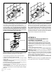
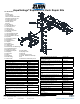
1.) Install stop valve assembly (A) using proper size supply
escutcheon and sweat solder adapter kit if applicable. Thread
sealing compounds should be used on male NPT threads only.
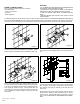
2.) Prior to inserting the ush valve tailpiece (B) into stop valve,
be certain that the O-ring seal (C) is located in O-ring seal groove
at the end of the tailpiece and the locking nut (D) and locking
snap ring (E) are located as shown. Care should be taken not
to damage the O-ring when inserting the tailpiece into the stop
valve. If lubrication is needed, wetting the O-ring with water will
be sufcient.
3.) Insert the ush valve tailpiece (B) into the stop valve (A) and
hand tighten the lock nut (D) to the stop valve. Plumb the entire
unit.
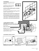
4.) Determine the length of vacuum breaker tube (F) required
to join the ush valve and xture spud. Cut the vacuum breaker
tube, if required, to this length. Assemble the vacuum breaker
tube assembly and spud nut assembly to the ush valve and
xture spud.
5.) Hand tighten spud nut and vacuum breaker tube nut to xture
and ush valve. Adjust the valve assembly for plumb. Tighten
xture spud nut, vacuum breaker tube nut and lock nut with a
wrench. Do not turn water on until batteries are inserted –
see 6.
Figure 1
Figure 3
Figure 2 Figure 4
E
C
A
D
F
B
B
D
A