
Use and Care Manual

FV237 Rev. F 6/25/2018
Page 4
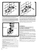
Before the supply water is turned on, be sure all stop valves to the
ush valves are closed off tight. The stop valves can be opened
and closed by using the adjusting screw located at the
center of the stop valve cap (T) , behind the adjusting screw cover
if already installed. Stop valve adjustments can only be made by
using the adjusting screw. It is not necessary to remove the
stop valve cap when making adjustments. If for any reason it
becomes necessary to remove the stop valve cap, be certain
the water is shut off at the main supply valve.
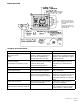
10.) The ZER ush valves are preset for xture volume as marked
on the valve cartons. The valve does not require regulation for
variation in water pressure within its operating range. To set the
ush valve for proper operation, gradually adjust the stop valve
open, using the adjusting screw, while actuating the valve until the
rate of water ow into the xture is not excessive, yet is sufcient
to adequately evacuate the waste. The nal setting for urinals
should be such that the xture will not overow when the valve
is actuated in succession. The stop cap screw cover should be
replaced after nal adjustments have been made.
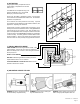
APPENDIX A
TO CHANGE ACTIVATION DISTANCE FOR
THE OBJECT LOCK SENSOR
1. Remove battery compartment tray as shown in Step 6.
2. Remove cover and sensor adjustor tool as shown in Step 6.
3. Replace battery compartment in E-Z Flush to activate unit.
4. Press sensor range reset button (the yellow L.E.D. will ash
continuously when it has an object in view for the 10-minute
reset period).
5. Stand at desired activation distance.
6. Use sensor adjustor tool and turn Distance Adjustment
Screw all the way down and then turn slowly up until yellow
L.E.D. begins to ash.
7. Ensure Object Lock Sensor is not detecting stall door or wall by
closing door, stepping out of sensor path and making sure yellow
L.E.D. is not ashing. If sensor locks onto door or wall, unit will
not ush properly. Shorten activation distance.
8. Remove battery compartment, replace sensor adjustor tool
and cover. Replace battery compartment tray to reactivate E-Z
Flush unit.
9. After 10-minute start-up sequence, the yellow L.E.D. will ash
only 3 times when a user is in view (after a 5-second delay).
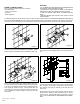
9.) When all ush valves are connected to the xtures and water
pressure is available, it is recommended that the supply piping be
ushed to remove dirt, pipe chips, etc., from system.
Use the following procedure to ush out the supply piping:
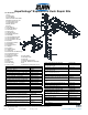
A. Remove the main valve body cover .(O)
B. Remove the working parts from the ush valve (P) and (Q)
(shown in 9b).
C. Replace the plastic cover (P) and main body cover (O) without
reinstalling the working parts.
D. Open the stop valve by using the stop adjusting screw and
ush out all debris from pipe and connections.
E. Shut stop, open cover, reinstall the working parts, replace both
covers and tighten.
This procedure should also be repeated when the system is
drained for seasonal use, as occurs in athletic elds, recreation
parks, etc.
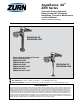
Working Parts
New RetroFlush
Diaphragm Kit
T
O
P
Q
Figure 9a
Figure 9b
Figure 10