
Setup guide


15IPL T Series • Setup
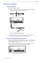
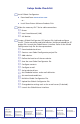
A cable that is wired as T568A at one end
and T568B at the other (Tx and Rx pairs
reversed) is a "crossover" cable.
A cable wired the same at both ends is
called a "straight-through" cable, because
no pin/pair assignments are swapped.
12345678
RJ-45
Connector
Insert Twisted
Pair Wires
Pins:
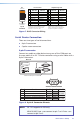
Crossover Cable Straight-through Cable
Pin
1
2
3
4
5
6
7
8
Wire color
White-green
Green
White-orange
Blue
White-blue
Orange
White-brown
Brown
Wire color
T568A T568B
End 1 End 2 End 1 End 2
White-orange
Orange
White-green
Blue
White-blue
Green
White-brown
Brown
Pin
1
2
3
4
5
6
7
8
Wire color
White-orange
White-green
Blue
White-blue
White-brown
Brown
Wire color
T568BT568B
White-orange
OrangeOrange
White-green
Blue
White-blue
GreenGreen
White-brown
Brown
Figure 7. RJ-45 Connector Wiring
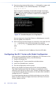
Serial Device Connection
There are two types of serial connections:
9-pin D connectors
Captive screw connectors
9-pin D connector
Connect any audio or video device to any one of the COM ports on
the rear panel of an IPL T S Series controller using a serial cable with a
9-pin D connector.
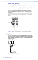
COM Ports with 9-pin D Connectors
IPL T S2
COM1
LAN
POWER
12V
.5A MAX
COM1
TX RX TX RX
COM2
COM2
MAC: 00-05-A6-XX-XX-XX
S/N:
Pin Function RS-232 RS-422 RS-485
3
Transmit Data/Transmit Data - TX TX-
2
Receive Data/Receive Data - RX RX-
7
Request to Send/Transmit Data + RTS TX+
8
Clear to Send/Receive Data + CTS RX+
Data -
Tie 2 & 3
5
Signal Ground GND GND GND
Data +
Tie 7 & 8
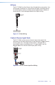
9-Pin D Connector Pinouts
5 1
9 6
Figure 8. 9-pin D Connector Pinouts
NOTE: IPL T S1 supports RS-232 only.
With RS-485, Data + can connect to pin 7 or 8. Data - can
connect to pin 2 or 3.