
Quick Installation Guide

5.5” Touch Panel
Quick Installation Guide
Consult the dealer or contact support@Zykronix.com for help
Opera II
English V1.2
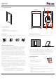
Device - Overview
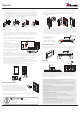
Planning the installation
The device is designed to be wall mounted in either Portrait or Landscape
orientation, or on tabletop with stand.
The device requires a minimum mounting depth of 1”(2.45cm) from the wall
surface to the room for cable/s. Power may be supplied by Power Over
Ethernet (PoE) or by a 24V DC power supply (not included). PoE connecting
must meets the IEEE 802.3af standard. Direct power connecting via a 24V DC
external power supply requires a minimum current output of 1A. The device
connects to the local network via a hard wired Ethernet connection.
Or connecting with WiFi in the case of the units with WiFi function.
Installing the device
A. Mounting height
The recommended mounting height
for the device is 57”- 65”
(145 cm -165 cm) from the finished
floor to the center of the unit.
B. Landscape/Portrait mounting
Device can be mounted and oriented in Portrait or Landscape.
Landscape:
Install the 1-gang junction box or low-voltage bracket horizontally with mounting
screw holes on the left and right sides.
Portrait:
Install the 1-gang box junction box or low-voltage bracket in its normal orientation
with mounting screw holes at the top and bottom.
165 cm / 65”
145 cm / 57”
On the wall On the stand
Part No.:89-670-1010-00
Standard NEMA
1-gang US electrical
junction box
Low-voltage mounting
ring Arlington LV1
UK standard 1-gang
electrical box
European 1-gang
electrical box
Included in the box
�1ea Device
�1ea Mounting bracket
�2ea Mounting screws #5 for EU/CH/UK 1 gang box
�2ea Mounting screws #6 for US 1 gang box
Introduction
To install the device you will also need one of the following electrical junction
boxes for the supplied mounting bracket.
Important safety instructions
Read, understand and follow ALL safety and installation instructions included
in this manual. Failure to follow the included documentation may damage the
product and will void the manufacturer’s warranty. Follow ALL installation
guidelines included with the product. Installation of the product in high
humidity environments, in close proximity to heat sources and/or
non-recommended locations WILL impede, interfere and/or damage the
intended operation of the product. Only use attachments and accessories
which have been specified for use by the manufacturer. The use of abrasive,
liquid or solvent-based cleaning fluids WILL damage the product. Product
Servicing may ONLY be completed by authorized or certified service centers &
personnel. For a complete list of product servicing options, please follow
instructions included in the product documentation and/or contact the original
manufacturer for details.
This equipment has been tested and found to comply with the limits for a Class
B digital device, pursuant to part 15 of the FCC Rules.
These limits are designed to provide reasonable protection against harmful
interference in a residential installation. This equipment generates, uses and
can radiate radio frequency energy and, if not installed and used in accordance
with the instructions, may cause harmful interference to radio communications.
However, there is no guarantee that interference will not occur in a particular
installation. If this equipment does cause harmful interference to radio or
television reception, which can be determined by turning the equipment off and
on, the user is encouraged to try to correct the interference by one or more of
the following measures:
- Reorient or relocate the receiving antenna.
- Increase the separation between the equipment and receiver.
- Connect the equipment into an outlet on a circuit different from that to
which the receiver is connected.
- Consult the dealer or an experienced radio/TV technician for help.
USB
Proximity and
Light Sensor
LAN + Power
over Ethernet
DC Power
Input
Speaker
Event
Key
MicrophoneMicrophone