
Quick Installation Guide
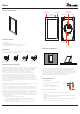

C. Installing the device mounting bracket
The device package includes a stainless steel mounting bracket that MUST be
used for installation. Using the included #5 screws to mount the mounting bracket
onto the EU/CH/UK 1 gang junction box. Using the included #6 screws to mount
the mounting bracket onto the US 1 gang junction box, low voltage bracket. Take
off the 2 original screws of the gang box before mounting! Verify that the bracket is
level before tightening the captive screws on the device. (Mounting Bracket Part
No.:84-9E0-0000-00)
Event key
Tap the button to reboot the device.
Thank you for including the device as part of the user interface strategy for your
customer. The device has been designed to provide years of trouble free
operation when wired and installed properly. The device is designed for
installation in low humidity indoor environments and should never be installed
outdoors or in high humidity areas.
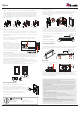
E. Mounting the device
Loosen the captive screws of the unit first. Screws should not be moved
apart from the unit. (Lossen for 4 loops.) Align the mounting bracket hooks
with the device mounting slots and gently press the unit toward the
mounting bracket/wall.
The device snaps in when pushed to its mounting bracket and held into the
mounting bracket by 2 mounting screws, located on the left and right sides
of the device when mounted in landscape mode. Orient the device for the
desired portrait or landscape mounting option. To complete the installation
insert the device into the included bracket and tighten the 2 captive screws
to secure the device to the mounting bracket.
When installing on to the
mounting bracket. Press only
on the frame edges.
CAUTION: DO NOT PRESS
DIRECTLY ON THE SCREEN
D. Connecting the device to power
The device is designed to be powered over the Ethernet connection (PoE) or
by connecting a 24V power supply (not included), but not both. If both the
PoE and a 24V power supply are connected, the device will draw power from
the 24V source.
When not utilizing PoE, it is recommended that you connect the device
directly to the network switch. Utilizing a T568A or T568B network cable
connects to the LAN/PoE jack.
PoE Connection
PoE connection requires IEEE 802.3af
standard. Utilize a network switch or
PoE injector that meets this standard.
Connect the device using a standard
T568A or T568B Ethernet cable from
the network switch to the LAN/PoE
jack on the back of the device.
24V DC Power Supply
You can provide power locally or remotely to device by utilizing a 24V DC
power supply (not included). Please note that running the wire through the
wall in accordance with local codes when powering locally. If powering
remotely, please ensure to use wire of adequate gauge for the length of the
run. Please use approved 24V DC power supply.
Verify the polarity of the barrel connector on your power supply before
connecting it to the device. The center pin of the device power connector is
positive and the outer ring is negative. If the wire is extended, please ensure
that the routing is in compliance with local codes.
Plug the connector into the device DC jack on the back of the device.
Network Switch
PoE Injector
To device
PoE Network Switch
Removing the device
Using a precision philips head screw driver to loosen the 2 captive screws on
the device and pull out from the wall (see picture below) following the step 1
and 2 in order.
Opus
English V1.1
Consult the dealer or contact support@Zykronix.com for help
On European 1-gang
electrical box
On UK standard 1-gang
electrical box
On standard NEMA 1-gang
US electrical junction box
On low-voltage mounting
ring-like Arlington LV1
Line in wall
24V DC
2.5mm
Coaxial Plug
Loosen
Tighten
Opus Frame
Top of 1 Gang Box
Dry Wall
Mounting Bracket
B
C
A
B
C
A
Top of 1 Gang Box
Dry Wall
Mounting Bracket
B
C
A
1
2
B
C
A
Opus Frame
Recessed
Event Key
Paper Clip
Temperature ranges/humidity
±0 °C to +45 °C
−20 °C to +70 °C
max. 95%(no condensation)
Operating
Storage/transport
Relative humidity
Powering up the device
The device will automatically power on when ower is
applied. Wait for the unit to boot up. When it's
connected to a network switch by Ethernet cable, the
device will acquire a etwork address via DHCP and
automatically onnect to the system.
If you are using an external power adapter/source,
connect the 2 Pin connector of the adapter/source to
device power jack.
Any changes or modifications not expressly approved by the grantee of this device could
void the user's authority to operate the equipment.
This device complies with Part 15 of the FCC Rules. Operation is subject to the following two
conditions: (1) this device may not cause harmful interference, and (2) this device must
accept any interference received, including interference that may cause undesired operation.
RF exposure warning
This equipment must be installed and operated in accordance with provided instructions and
the antenna(s) used for this transmitter must be installed to provide a separation distance of
at least 20 cm from all persons and must not be co-located or operating in conjunction with
any other antenna or transmitter. End-users and installers must be provide with antenna
installation instructions and transmitter operating conditions for satisfying RF exposure
compliance.
Canada, Industry Canada (IC) Notices
This device complies with Canada licence-exempt RSS standard(s).
Operation is subject to the following two conditions: (1) this device may not cause
interference, and (2) this device must accept any interference, including interference that may
cause undesired operation of the device.
Canada, avis d'Industry Canada (IC)
Cet appareil est conforme avec Industrie Canada exemptes de licence RSS standard(s).
Son fonctionnement est soumis aux deux conditions suivantes : (1) cet appareil ne doit pas
causer d'interférence et (2) cet appareil doit accepter toute interférence, notamment les
interférences qui peuvent affecter son fonctionnement.