User’s Guide NWA50AX 802.11ax (WiFi6) Dual-Radio PoE Access Point Default Login Details Management IP Address User Name Password Version 6.20 Edition 1, 4/2021 http://DHCP-assigned IP OR http://192.168.1.
IMPORTANT! READ CAREFULLY BEFORE USE. KEEP THIS GUIDE FOR FUTURE REFERENCE. This is a User’s Guide for a series of products. Not all products support all firmware features. Screenshots and graphics in this book may differ slightly from your product due to differences in your product hardware, firmware, or your computer operating system. Every effort has been made to ensure that the information in this manual is accurate.
Document Conventions Warnings and Notes These are how warnings and notes are shown in this guide. Warnings tell you about things that could harm you or your device. Note: Notes tell you other important information (for example, other things you may need to configure or helpful tips) or recommendations. Syntax Conventions • All models in this series may be referred to as the “Zyxel Device” in this guide. • Product labels, screen names, field labels and field choices are all in bold font.
Contents Overview Contents Overview Introduction ........................................................................................................................................... 12 AP Management .................................................................................................................................. 20 Hardware ...............................................................................................................................................
Table of Contents Table of Contents Document Conventions ......................................................................................................................3 Contents Overview .............................................................................................................................4 Table of Contents .................................................................................................................................5 Chapter 1 Introduction .................
Table of Contents 4.3.1 Title Bar ................................................................................................................................... 34 4.3.2 Navigation Panel .................................................................................................................. 35 4.3.3 Standalone Mode Navigation Panel Menus ..................................................................... 35 4.3.4 Cloud Mode Navigation Panel Menus ...........................................
Table of Contents 8.8 View Log .......................................................................................................................................... 66 Chapter 9 Network...............................................................................................................................................69 9.1 Overview ......................................................................................................................................... 69 9.1.
Table of Contents 12.5 MAC Filter List .............................................................................................................................. 115 12.5.1 Add/Edit MAC Filter Profile ............................................................................................... 115 Chapter 13 MON Profile.......................................................................................................................................117 13.1 Overview ..............................
Table of Contents 16.4.3 HTTPS ................................................................................................................................... 143 16.4.4 Configuring WWW Service Control ................................................................................. 144 16.4.5 HTTPS Example ................................................................................................................... 145 16.5 SSH .....................................................................
Table of Contents 20.2 Suppression Screen .................................................................................................................... 180 20.3 Locator Screen ........................................................................................................................... 181 Chapter 21 Reboot...............................................................................................................................................183 21.1 Overview .....................
Table of Contents Chapter 26 Troubleshooting................................................................................................................................198 26.1 Overview ..................................................................................................................................... 198 26.2 Power, Hardware Connections, and LED ................................................................................ 198 26.3 Zyxel Device Management, Access, and Login ........
CHAPTER 1 Introduction 1.1 Overview The Zyxel Device can be managed in one of the following methods: remote management through Nebula Control Center (NCC) or local management in Standalone Mode. The Zyxel Device runs in standalone mode by default, but it is recommended to use NCC management if it is available for your device. For more information about Access Point (AP) management, see Section 2.1 on page 20. Use the Zyxel Device to set up a wireless network with other IEEE 802.
Chapter 1 Introduction Figure 1 Sample Network Setup 1.2.1 Root AP In Root AP mode, you can have multiple SSIDs active for regular wireless connections and one SSID for the connection with a repeater (repeater SSID). Wireless clients can use either SSID to associate with the Zyxel Device in Root AP mode. A repeater must use the repeater SSID to connect to the Zyxel Device in Root AP mode.
Chapter 1 Introduction Figure 2 Repeater Application When the Zyxel Device is in Repeater mode, repeater security between the Zyxel Device and other repeater is independent of the security between the wireless clients and the AP or repeater. When repeater security is enabled, both APs and repeaters must use the same pre-shared key. See Section 10.2 on page 76 and Section 14.2 on page 120 for more details.
Chapter 1 Introduction The models that do not support MON Mode support Rogue AP Detection (see Section 10.3 on page 79). Rogue AP Detection allows the AP to scan all channels similar to MON Mode except that the Zyxel Device still works as an AP while it scans the environment for wireless signals. To see which Zyxel Devices support the RF Monitor feature, see Section 1.4 on page 18. The Zyxel Device in MON Mode scans a range of WiFi channels that you specify in a MON Profile, either in the 2.
Chapter 1 Introduction 7 To quarantine a rogue AP, go to CONFIGURATION > Wireless > Rogue AP, select the APs you want to quarantine, and click Containment. Make sure the Enable Rogue AP Containment check box is selected, and click Apply. 1.3 Sample Feature Applications This section describes some possible scenarios and topologies that you can set up using your Zyxel Device. 1.3.
Chapter 1 Introduction Figure 3 Multiple BSSs 1.3.2 Dual-Radio Some of the Zyxel Device models are equipped with dual wireless radios. This means you can configure two different wireless networks to operate simultaneously. Note: A different channel should be configured for each WLAN interface to reduce the effects of radio interference. You could use the 2.
Chapter 1 Introduction Figure 4 Dual-Radio Application 1.4 Zyxel Device Product Feature The following table lists the features of the Zyxel Device.. Table 1 Zyxel Device Product Feature Table FEATURES NWA50AX Supported Wireless Standards IEEE 802.11a IEEE802.11b IEEE 802.11g IEEE 802.11n IEEE 802.11ac IEEE802.11ax Supported Frequency Bands 2.
Chapter 1 Introduction Table 1 Zyxel Device Product Feature Table (continued) FEATURES NWA50AX Antenna Switch No Console Port 4-Pin Serial LED Locator Yes LED Suppression Yes AC (AP Controller) Discovery No NebulaFlex PRO No NCC Discovery Yes 802.11r Fast Roaming Support Yes 802.11k/v Assisted Roaming Yes Bluetooth Low Energy (BLE) No USB Port for BLE No Ethernet Storm Control No Grounding No Power Jack Yes Maximum number of log messages 512 event logs A.
Chapter 2 AP Management CHAPTER 2 AP Management 2.1 Management Mode The Zyxel Device is a unified AP and can be managed by the NCC or work as a standalone device. We recommend you use NCC to manage multiple APs (see the NCC User’s Guide). Note: Not all models can be managed by NCC or an AC. See Section 1.4 on page 18 to check whether your product supports these. The following table shows the default IP addresses and firmware upload methods for different management modes.
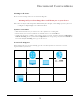
Chapter 2 AP Management switches and gateways. Your network can also be managed through your smartphone using the Nebula Mobile app. See Section 23.1 on page 186 for an example NCC managed network topology. NCC allows different levels of management. You can configure each device on its own or configure a set of devices together as a site. You can also monitor groups of sites called organizations, as shown below.
Chapter 2 AP Management See the NCC (Nebula Control Center) User’s Guide for how to configure Nebula managed devices. See Chapter 24 on page 189 if you want to change the Zyxel Device’s VLAN setting or manually set its IP address. Note: Make sure your network firewall allows TCP ports 443, 4335, and 6667 as well as UDP port 123 so the device can connect to and sync with the NCC. 2.2 Switching Management Modes The Zyxel Device is in standalone mode by default, with NCC and/or AC discovery enabled.
Note: To check for your Windows operating system version, right-click on My Computer > Properties. You should see this information in the General tab. Note: It is suggested that you install Npcap, the packet capture library for Windows operating systems, and remove WinPcap or any other installed packet capture tools before you install the ZON utility. Hardware Here are the minimum hardware requirements to use the ZON Utility on your PC.
Chapter 2 AP Management model and firmware version link. If your device is not listed here, see the device release notes for ZON utility support. The release notes are in the firmware zip file on the Zyxel web site. Figure 7 ZON Utility Screen 3 Select a network adapter to which your supported devices are connected. Figure 8 Network Adapter 4 Click the Go button for the ZON Utility to discover all supported devices in your network.
Chapter 2 AP Management Figure 10 ZON Utility Screen 6 Select a device and then use the icons to perform actions. Some functions may not be available for your devices. Note: You must know the selected device admin password before taking actions on the device using the ZON utility icons. Figure 11 Password Prompt The following table describes the icons numbered from left to right in the ZON Utility screen.
Chapter 2 AP Management Table 4 ZON Utility Icons (continued) ICON DESCRIPTION 9 Configure NCC Discovery You must have Internet access to use this feature. Use this icon to enable or disable the Nebula Control Center (NCC) discovery feature on the selected device. If it is enabled, the selected device will try to connect to the NCC. Once the selected device is connected to and has registered in the NCC, it will go into the Nebula cloud management mode.
Chapter 2 AP Management NCC This is the primary means by which you manage the Zyxel Device in cloud (NCC) mode. With the NCC, you can remotely manage and monitor the Zyxel Device through a cloud-based network management system. See the NCC User’s Guide for more information. ZON Utility Zyxel One Network (ZON) Utility is a utility tool that assists you to set up and maintain network devices in a simple and efficient way. You can download the ZON Utility at www.zyxel.
Chapter 3 Hardware CHAPTER 3 Hardware See the Quick Start Guide for hardware installation and connections. 3.1 Zyxel Device Single LED The LED of the Zyxel Device can be controlled by using the suppression feature such that the LEDs stay lit (ON) or OFF after the Zyxel Device is ready. Refer to Chapter 20 on page 180 for the LED Suppression and Locator menus in standalone mode. 3.1.
Chapter 3 Hardware The following are the LED descriptions for your Zyxel Device. Table 6 Zyxel Device LED COLOR STATUS DESCRIPTION Blinks amber for 1 second and green for 1 second alternatively. The Zyxel Device is booting up or is connecting with NCC. Blinks amber and green alternatively 3 times and then turns solid green for 3 seconds. The Zyxel Device is discovering the NCC or an AC. Blinks amber and green alternatively 2 times and then turns solid green for 3 seconds.
CHAPTER 4 Web Configurator 4.1 Overview The Web Configurator is an HTML-based management interface that allows easy system setup and management via internet browser. Use a browser that supports HTML5, such Internet Explorer 11, Mozilla Firefox, or Google Chrome. The recommended screen resolution is 1024 by 768 pixels. In order to use the Web Configurator you need to allow: • Web browser pop-up windows from your device. • JavaScript (enabled by default). • Java permissions (enabled by default). 4.
Chapter 4 Web Configurator If a Zyxel Device is in standalone mode and supports NCC, the login page displays as shown in the following figure. Click Nebula Mode to show the following screen. Here, you can watch a tutorial for using the Zyxel Nebula Control Center (NCC) or access the link to the NCC, as shown in the following figure. Otherwise, continue with the next step.
Chapter 4 Web Configurator remotely manage and monitor the Zyxel Device (see Section 2.1.2 on page 20). If you want to return to the login page, click Standalone Mode and follow the next steps. 4 Enter the user name (default: “admin”) and password (default: “1234”). If the Zyxel Device is being managed or has been managed by the NCC, check the NCC's Site-Wide > Configure > General setting screen for the Zyxel Device's current password. 5 Select the language you prefer for the Web Configurator.
Chapter 4 Web Configurator 4.3 Navigating the Web Configurator The following summarizes how to navigate the Web Configurator from the Dashboard screen. The following figures show the Dashboard screen for standalone mode and for cloud (NCC) mode. The screen is different for standalone mode and cloud (NCC) mode and may vary slightly for different models.
Chapter 4 Web Configurator 4.3.1 Title Bar The title bar provides some useful links that always appear over the screens below, regardless of how deep into the Web Configurator you navigate. If your Zyxel Device is in NCC mode, not all icons will be available in the Title Bar. Figure 15 Title Bar The icons provide the following functions. Table 7 Title Bar: Web Configurator Icons LABEL DESCRIPTION Wizard Click this to open the wizard. See Chapter 7 on page 49 for more information.
Chapter 4 Web Configurator CLI Messages Click CLI to look at the CLI commands sent by the Web Configurator. These commands appear in a popup window, such as the following. Figure 17 CLI Messages Click Clear to remove the currently displayed information. Note: See the Command Reference Guide for information about the commands. 4.3.2 Navigation Panel Use the menu items on the navigation panel to open screens to configure Zyxel Device features.
Chapter 4 Web Configurator Dashboard The dashboard displays general device information, system status, system resource usage, and interface status in widgets that you can re-arrange to suit your needs. For details on the Dashboard’s features, see Chapter 6 on page 44. Monitor Menu The monitor menu screens display status and statistics information.
Chapter 4 Web Configurator Table 9 Configuration Menu Screens Summary (continued) FOLDER OR LINK TAB FUNCTION WDS Profile WDS Create and manage WDS profiles that can be used to connect to different APs in WDS. Certificate My Certificates Create and manage th e Zyxel Device’s certificates. Trusted Certificates Import and manage certificates from trusted sources. Host Name Host Name Configure the system and domain name for the Zyxel Device.
Chapter 4 Web Configurator Configuration Menu Use the configuration menu screens to configure the Zyxel Device’s features. Table 11 Configuration Menu Screens Summary FOLDER OR LINK TAB FUNCTION Network IP Setting Configure the IP address for the Zyxel Device Ethernet interface. VLAN Manage the Ethernet interface VLAN settings. 4.3.5 Tables and Lists The Web Configurator tables and lists are quite flexible and provide several options for how to display their entries. 4.3.5.
Chapter 4 Web Configurator 3 Select a column heading cell’s right border and drag to re-size the column. 4 Select a column heading and drag and drop it to change the column order. A green check mark displays next to the column’s title when you drag the column to a valid new location. 5 Use the icons and fields at the bottom of the table to navigate to different pages of entries and control how many entries display at a time.
Chapter 4 Web Configurator 4.3.5.2 Working with Table Entries The tables have icons for working with table entries. A sample is shown next. You can often use the [Shift] or [Ctrl] key to select multiple entries to remove, activate, or deactivate. Figure 19 Common Table Icons Here are descriptions for the most common table icons. Table 12 Common Table Icons LABEL DESCRIPTION Add Click this to create a new entry.
P ART I Standalone Configuration 41
CHAPTER 5 Standalone Configuration 5.1 Overview The Zyxel Device is in standalone mode by default. Use the web configurator to manage and configure the Zyxel Device directly. As shown in the following figure, wireless clients can connect to the Zyxel Device (A) to access network resources. 5.2 Starting and Stopping the Zyxel Device Here are some of the ways to start and stop the Zyxel Device.
Chapter 5 Standalone Configuration Table 13 Starting and Stopping the Zyxel Device METHOD DESCRIPTION Using the RESET button If you press the RESET button on the back of the Zyxel Device, the Zyxel Device sets the configuration to its default values and then reboots. See Section 26.6 on page 205 for more information.
CHAPTER 6 Dashboard 6.1 Overview This screen displays general device information, system status, system resource usage, and interface status in widgets that you can re-arrange to suit your needs. You can also collapse, refresh, and close individual widgets. Figure 20 Dashboard The following table describes the labels in this screen. Table 14 Dashboard LABEL DESCRIPTION Widget Settings (A) Use this link to re-open closed widgets. Widgets that are already open appear grayed out.
Chapter 6 Dashboard Table 14 Dashboard (continued) LABEL DESCRIPTION MAC Address Range This field displays the MAC addresses used by the Zyxel Device. Each physical port or wireless radio has one MAC address. The first MAC address is assigned to the Ethernet LAN port, the second MAC address is assigned to the first radio, and so on. Firmware Version This field displays the version number and date of the firmware the Zyxel Device is currently running.
Chapter 6 Dashboard Table 14 Dashboard (continued) LABEL Boot Status DESCRIPTION This field displays details about the Zyxel Device’s startup state. OK - The Zyxel Device started up successfully. Firmware update OK - A firmware update was successful. Problematic configuration after firmware update - The application of the configuration failed after a firmware upgrade. System default configuration - The Zyxel Device successfully applied the system default configuration.
Chapter 6 Dashboard Table 14 Dashboard (continued) LABEL DESCRIPTION Channel This indicates the channel number the radio is using. Antenna This indicates the antenna orientation for the radio (Wall or Ceiling). This field is not available if the Zyxel Device does not allow you to adjust antenna orientation for the Zyxel Device’s radio(s) using the web configurator or a physical switch. Refer to Section 1.4 on page 18 to see if your Zyxel Device has an antenna switch.
Chapter 6 Dashboard 6.1.2 Memory Usage Use this screen to look at a chart of the Zyxel Device’s recent memory (RAM) usage. To access this screen, click Memory Usage in the dashboard. Figure 22 Dashboard > Memory Usage The following table describes the labels in this screen. Table 16 Dashboard > Memory Usage LABEL DESCRIPTION % The y-axis represents the percentage of RAM usage.
CHAPTER 7 Setup Wizard 7.1 Accessing the Wizard When you log into the Web Configurator for the first time or when you reset the Zyxel Device to its default configuration, the wizard screen displays. Note: If you have already configured the wizard screens and want to open it again, click the Wizard icon on the upper right corner of any Web Configurator screen. 7.
Chapter 7 Setup Wizard Figure 23 Wizard: Time Settings 7.2.2 Step 2 Password and Uplink Connection Use this screen to configure the Zyxel Device’s system password and IP address. Change Password: Enter a new password and retype it to confirm. Uplink Connection: Select Auto (DHCP) if the Zyxel Device is connected to a router with the DHCP server enabled. You then need to check the router for the IP address assigned to the Zyxel Device in order to access the Zyxel Device’s Web Configurator again.
Chapter 7 Setup Wizard Figure 24 Wizard: Change Password and Uplink Connection 7.2.3 Step 3 Radio Use this screen to configure the Zyxel Device’s radio transmitter(s). • Channel Selection: Select Auto to have the Zyxel Device automatically choose a radio channel that has least interference. Otherwise, select Manual and specify a channel the Zyxel Device will use in the 2.4 GHz or 5 GHz wireless LAN. The options vary depending on the frequency band and the country you are in.
Chapter 7 Setup Wizard 7.2.4 Step 4 SSID Use this screen to enable, disable or edit an SSID profile. Select an SSID profile and click the Status switch to turn it on or off. To change an SSID profile’s settings, such as the SSID (WiFi network name) and WiFi password, double-click the SSID profile entry from the list. See Section 7.2.4.1 on page 52 for more information. Note: You cannot add or remove an SSID profile after running the setup wizard. Figure 26 Wizard: SSID 7.2.4.
Chapter 7 Setup Wizard Figure 27 Wizard: Summary NWA50AX User’s Guide 53
CHAPTER 8 Monitor 8.1 Overview Use the Monitor screens to check status and statistics information. 8.1.1 What You Can Do in this Chapter • The Network Status screen (Section 8.3 on page 55) displays general LAN interface information and packet statistics. • The AP Information > Radio List screen (Section 8.4 on page 57) displays statistics about the wireless radio transmitters in the Zyxel Device. • The Station Info screen (Section 8.5 on page 61) displays statistics pertaining to the associated stations.
Chapter 8 Monitor 8.3 Network Status Use this screen to look at general Ethernet interface information and packet statistics. To access this screen, click Monitor > Network Status. Figure 28 Monitor > Network Status The following table describes the labels in this screen. Table 17 Monitor > Network Status LABEL DESCRIPTION Interface Summary Use the Interface Summary section for IPv4 network settings.
Chapter 8 Monitor Table 17 Monitor > Network Status (continued) LABEL DESCRIPTION Set Interval Click this to set the Poll Interval the screen uses. Stop Click this to stop the window from updating automatically. You can start it again by setting the Poll Interval and clicking Set Interval. Switch to Graphic View Click this to display the port statistics as a line graph. Name This field displays the name of the interface. Status This field displays the current status of the physical port.
Chapter 8 Monitor Figure 29 Monitor > Network Status > Switch to Graphic View The following table describes the labels in this screen. Table 18 Monitor > Network Status > Switch to Graphic View LABEL DESCRIPTION Refresh Interval Enter how often you want this window to be automatically updated. Refresh Now Click this to update the information in the window right away. Port Selection Select the Ethernet port for which you want to view the packet statistics.
Chapter 8 Monitor Figure 30 Monitor > Wireless > AP Information > Radio List (for Zyxel Device that supports WDS) Figure 31 Monitor > Wireless > AP Information > Radio List (for Zyxel Device that does not support WDS) The following table describes the labels in this screen. Table 19 Monitor > Wireless > AP Information > Radio List LABEL DESCRIPTION More Information Click this to view additional information about the selected radio’s wireless traffic and station count.
Chapter 8 Monitor Table 19 Monitor > Wireless > AP Information > Radio List (continued) LABEL DESCRIPTION Upload This displays the total number of packets received by the radio. Download This displays the total number of packets transmitted by the radio. Channel Utilization This indicates how much IEEE 802.11 traffic the radio can receive on the channel. It displays what percentage of the radio’s channel is currently being used. 8.4.
Chapter 8 Monitor Figure 32 Monitor > Wireless > AP Information > Radio List > More Information The following table describes the labels in this screen. Table 20 Monitor > Wireless > AP Information > Radio List > More Information LABEL DESCRIPTION SSID Detail This list shows information about all the wireless clients that have connected to the specified radio over the preceding 24 hours. # This is the items sequential number in the list. It has no bearing on the actual data in this list.
Chapter 8 Monitor Table 20 Monitor > Wireless > AP Information > Radio List > More Information (continued) LABEL DESCRIPTION SSID Name This displays an SSID associated with this radio. There can be up to eight maximum. BSSID This displays a BSSID associated with this radio. The BSSID is tied to the SSID. Security Mode This displays the security mode in which the SSID is operating. VLAN This displays the VLAN ID associated with the SSID.
Chapter 8 Monitor Table 21 Monitor > Wireless > Station Info (continued) LABEL DESCRIPTION SSID Name This indicates the name of the wireless network to which the station is connected. A single AP can have multiple SSIDs or networks. Security Mode This indicates which secure encryption methods is being used by the station to connect to the network. Signal Strength This is the RSSI (Received Signal Strength Indicator) of the station’s wireless connection.
Chapter 8 Monitor Table 22 Monitor > Wireless > WDS Link Info (continued) LABEL DESCRIPTION MAC Address This is the MAC address of the root AP or repeater to which the Zyxel Device is connected using WDS. Radio This is the radio number on the root AP or repeater to which the Zyxel Device is connected using WDS. SSID Name This indicates the name of the wireless network to which the Zyxel Device is connected using WDS.
Chapter 8 Monitor Figure 35 Monitor > Wireless > Detected Device (for Zyxel Device that supports Monitor mode) NWA50AX User’s Guide 64
Chapter 8 Monitor Figure 36 Monitor > Wireless > Detected Device (for Zyxel Device that does not support Monitor mode) The following table describes the labels in this screen. Table 23 Monitor > Wireless > Detected Device LABEL DESCRIPTION Discovered APs Rogue AP This shows how many devices are detected as rogue APs. Suspected rogue AP This shows how many devices are detected as possible rogue APs based on the classification rule(s) in Section 10.3 on page 79.
Chapter 8 Monitor Table 23 Monitor > Wireless > Detected Device (continued) LABEL DESCRIPTION Mark as Rogue AP Click this button to mark the selected AP as a rogue AP. For more on managing rogue APs, see the Configuration > Wireless > Rogue AP screen (Section 10.3 on page 79). Mark as Friendly AP Click this button to mark the selected AP as a friendly AP. For more on managing friendly APs, see the Configuration > Wireless > Rogue AP screen (Section 10.3 on page 79).
Chapter 8 Monitor Figure 37 Monitor > Log > View Log The following table describes the labels in this screen. Table 24 Monitor > Log > View Log LABEL DESCRIPTION Show Filter / Hide Filter Click this button to show or hide the filter settings. If the filter settings are hidden, the Display, Email Log Now, Refresh, and Clear Log fields are available.
Chapter 8 Monitor Table 24 Monitor > Log > View Log (continued) LABEL DESCRIPTION Destination Address This displays when you show the filter. Type the IP address of the destination of the incoming packet when the log message was generated. Do not include the port in this filter. Source Interface This displays when you show the filter. Select the source interface of the packet that generated the log message. Destination Interface This displays when you show the filter.
CHAPTER 9 Network 9.1 Overview This chapter describes how you can configure the management IP address and VLAN settings of your Zyxel Device. The Internet Protocol (IP) address identifies a device on a network. Every networking device (including computers, servers, routers, printers, etc.) needs an IP address to communicate across the network. These networking devices are also known as hosts. Figure 38 IP Setup The figure above illustrates one possible setup of your Zyxel Device.
Chapter 9 Network Figure 39 Configuration > Network > IP Setting Each field is described in the following table. Table 25 Configuration > Network > IP Setting LABEL DESCRIPTION IP Address Assignment Get Automatically Select this to make the interface a DHCP client and automatically get the IP address, subnet mask, and gateway address from a DHCP server. Use Fixed IP Address Select this if you want to specify the IP address, subnet mask, and gateway manually.
Chapter 9 Network Table 25 Configuration > Network > IP Setting (continued) LABEL IPv6 Address/ Prefix Length DESCRIPTION Enter the IPv6 address and the prefix length for the LAN interface if you want to use a static IP address. This field is optional. The prefix length indicates what the left-most part of the IP address is the same for all computers in the network, that is, the network address. Gateway Enter the IPv6 address of the default outgoing gateway using colon (:) hexadecimal notation.
Chapter 9 Network In the figure above, to access and manage the Zyxel Device from computer A, the Zyxel Device and switch B’s ports to which computer A and the Zyxel Device are connected should be in the same VLAN. A Virtual Local Area Network (VLAN) allows a physical network to be partitioned into multiple logical networks. Devices on a logical network belong to one group. A device can belong to more than one group.
Chapter 9 Network Table 26 Configuration > Network > VLAN (continued) LABEL DESCRIPTION Status This field indicates whether the port is enabled (a yellow bulb) or not (a gray bulb). Port This field displays the name of the port. PVID This field displays the port number of the VLAN ID. VLAN Configuration Add Click this to create a new entry.
Chapter 9 Network Figure 42 Configuration > Network > NCC Discovery Each field is described in the following table. Table 27 Configuration > Network > NCC Discovery LABEL DESCRIPTION Nebula Control Center Status Internet This field displays whether the Zyxel Device can connect to the Internet. Nebula Connectivity This field displays whether the Zyxel Device can connect to the Zyxel Nebula Control Center (NCC).
C H A P T E R 10 Wireless 10.1 Overview This chapter discusses how to configure the wireless network settings in your Zyxel Device. The following figure provides an example of a wireless network. Figure 43 Example of a Wireless Network The wireless network is the part in the blue circle. In this wireless network, devices A and B are called wireless clients. The wireless clients use the access point (AP) to interact with other devices (such as the printer) or with the Internet. Your Zyxel Device is the AP.
Chapter 10 Wireless 10.1.2 What You Need to Know The following terms and concepts may help as you read this chapter. Station / Wireless Client A station or wireless client is any wireless-capable device that can connect to an AP using a wireless signal. Dynamic Channel Selection (DCS) Dynamic Channel Selection (DCS) is a feature that allows an AP to automatically select the radio channel which it broadcasts. For more information, see Section 10.5 on page 84. 10.
Chapter 10 Wireless Figure 44 Configuration > Wireless > AP Management Each field is described in the following table. Table 28 Configuration > Wireless > AP Management LABEL DESCRIPTION Radio 1 Setting Radio 1 Activate Select the check box to enable the Zyxel Device’s first (default) radio.
Chapter 10 Wireless Table 28 Configuration > Wireless > AP Management (continued) LABEL DESCRIPTION Radio 1 OP Mode Select the operating mode for radio 1. AP Mode means the radio can receive connections from wireless clients and pass their data traffic through to the Zyxel Device to be managed (or subsequently passed on to an upstream gateway for managing).
Chapter 10 Wireless Table 28 Configuration > Wireless > AP Management (continued) LABEL DESCRIPTION Radio 2 OP Mode This displays if the Zyxel Device has a second radio. Select the operating mode for radio 2. AP Mode means the radio can receive connections from wireless clients and pass their data traffic through to the Zyxel Device to be managed (or subsequently passed on to an upstream gateway for managing).
Chapter 10 Wireless Rogue APs A rogue AP is a wireless access point operating in a network’s coverage area that is not under the control of the network administrator, and which can potentially open up holes in a network’s security. In the following example, a corporate network’s security is compromised by a rogue AP (RG) set up by an employee at his workstation in order to allow him to connect his notebook computer wirelessly (A).
Chapter 10 Wireless know which models support Rogue AP Detection. Note: Enabling Rogue AP Detection might affect the performance of wireless clients associated with the Zyxel Device.
Chapter 10 Wireless Figure 47 Configuration > Wireless > Rogue AP (for Zyxel Devices that support Rogue AP Detection) Each field is described in the following table. Table 29 Configuration > Wireless > Rogue AP LABEL DESCRIPTION Rogue AP Detection Setting Enable Rogue AP Detection Select this check box to detect Rogue APs in the network.
Chapter 10 Wireless Table 29 Configuration > Wireless > Rogue AP (continued) LABEL DESCRIPTION Role This field indicates whether the selected AP is a rogue-ap or a friendly-ap. To change the AP’s role, click the Edit button. MAC Address This field indicates the AP’s radio MAC address. Description Rogue/Friendly AP List Importing/Exporting File Path / Browse / Importing This field displays the AP’s description. You can modify this by clicking the Edit button.
Chapter 10 Wireless Figure 49 Configuration > Wireless > DCS Each field is described in the following table. Table 31 Configuration > Wireless > DCS LABEL DESCRIPTION DCS Now Click this to have the Zyxel Device scan for and select an available channel immediately. Apply Click Apply to save your changes back to the Zyxel Device. Reset Click Reset to return the screen to its last-saved settings. 10.
Chapter 10 Wireless Three channels are situated in such a way as to create almost no interference with one another if used exclusively: 1, 6 and 11. When an AP broadcasts on any of these 3 channels, it should not interfere with neighboring APs as long as they are also limited to same trio. Figure 51 An Example Four-Channel Deployment However, some regions require the use of other channels and often use a safety scheme with the following four channels: 1, 4, 7 and 11.
C H A P T E R 11 User 11.1 Overview This chapter describes how to set up user accounts and user settings for the Zyxel Device. 11.1.1 What You Can Do in this Chapter • The User screen (see Section 11.2 on page 87) provides a summary of all user accounts. • The Setting screen (see Section 11.3 on page 89) controls default settings, login settings, lockout settings, and other user settings for the Zyxel Device. 11.1.2 What You Need To Know The following terms and concepts may help as you read this chapter.
Chapter 11 User 11.2 User Summary The User screen provides a summary of all user accounts. To access this screen click Configuration > Object > User. Figure 53 Configuration > Object > User The following table describes the labels in this screen. Table 33 Configuration > Object > User LABEL DESCRIPTION Add Click this to create a new entry. Edit Double-click an entry or select it and click Edit to open a screen where you can modify the entry’s settings.
Chapter 11 User • - [dashes] The first character must be alphabetical (A-Z a-z), an underscore (_), or a dash (-). Other limitations on user names are: • User names are case-sensitive. If you enter a user 'bob' but use 'BOB' when connecting via CIFS or FTP, it will use the account settings used for 'BOB' not ‘bob’. • User names have to be different than user group names.
Chapter 11 User Table 34 Configuration > User > User > Add/Edit A User (continued) LABEL DESCRIPTION Authentication Timeout Settings This field is not available if the user type is user. Lease Time This field is not available if the user type is user. If you want to set authentication timeout to a value other than the default settings, select Use Manual Settings then fill your preferred values in the fields that follow.
Chapter 11 User Figure 55 Configuration > Object > User > Setting The following table describes the labels in this screen. Table 35 Configuration > Object > User > Setting LABEL DESCRIPTION User Default Setting Default Authentication Timeout Settings These authentication timeout settings are used by default when you create a new user account. They also control the settings for any existing user accounts that are set to use the default settings.
Chapter 11 User Table 35 Configuration > Object > User > Setting (continued) LABEL DESCRIPTION Limit the number of simultaneous logons for administration account Select this check box if you want to set a limit on the number of simultaneous logins by admin users. If you do not select this, admin users can login as many times as they want at the same time using the same or different IP addresses. Maximum number per administration account This field is effective when Limit ...
Chapter 11 User The following table describes the labels in this screen. Table 36 User > Setting > Edit User Authentication Timeout Settings LABEL DESCRIPTION User Type This read-only field identifies the type of user account for which you are configuring the default settings. • • Lease Time admin - this user can look at and change the configuration of the Zyxel Device. limited-admin - this user can look at the configuration of the Zyxel Device but not to change it.
C H A P T E R 12 AP Profile 12.1 Overview This chapter shows you how to configure preset profiles for the Zyxel Device. 12.1.1 What You Can Do in this Chapter • The Radio screen (Section 12.2 on page 94) creates radio configurations that can be used by the APs. • The SSID screen (Section 12.3 on page 100) configures three different types of profiles for your networked APs. 12.1.2 What You Need To Know The following terms and concepts may help as you read this chapter.
Chapter 12 AP Profile WEP WEP (Wired Equivalent Privacy) encryption scrambles all data packets transmitted between the AP and the wireless stations associated with it in order to keep network communications private. Both the wireless stations and the access points must use the same WEP key for data encryption and decryption. WPA2 WPA2 (IEEE 802.11i) is a wireless security standard that defines stronger encryption, authentication and key management than WPA.
Chapter 12 AP Profile Figure 57 Configuration > Object > AP Profile > Radio The following table describes the labels in this screen. Table 37 Configuration > Object > AP Profile > Radio LABEL DESCRIPTION Add Click this to add a new radio profile. Edit Click this to edit the selected radio profile. Remove Click this to remove the selected radio profile. Activate To turn on an entry, select it and click Activate. Inactivate To turn off an entry, select it and click Inactivate.
Chapter 12 AP Profile Figure 58 Configuration > Object > AP Profile > Radio > Add/Edit The following table describes the labels in this screen. Table 38 Configuration > Object > AP Profile > Radio > Add/Edit LABEL DESCRIPTION Hide / Show Advanced Settings Click this to hide or show the Advanced Settings in this window. General Settings Activate Select this option to make this profile active. Profile Name Enter up to 31 alphanumeric characters to be used as this profile’s name.
Chapter 12 AP Profile Table 38 Configuration > Object > AP Profile > Radio > Add/Edit (continued) LABEL 802.11 Mode DESCRIPTION Select how to let wireless clients connect to the AP. If 802.11 Band is set to 2.4G: • • • 11b/g: allows either IEEE 802.11b or IEEE 802.11g compliant WLAN devices to associate with the Zyxel Device. The Zyxel Device adjusts the transmission rate automatically according to the wireless standard supported by the wireless devices. 11n: allows IEEE802.11b, IEEE802.11g and IEEE802.
Chapter 12 AP Profile Table 38 Configuration > Object > AP Profile > Radio > Add/Edit (continued) LABEL 2.4 GHz Channel Selection Method DESCRIPTION This field is available when you set Channel Selection to DCS. Select how you want to specify the channels the Zyxel Device switches between for 2.4 GHz operation. Select auto to have the Zyxel Device display a 2.4 GHz Channel Deployment field you can use to limit channel switching to 3 or 4 channels.
Chapter 12 AP Profile Table 38 Configuration > Object > AP Profile > Radio > Add/Edit (continued) LABEL DESCRIPTION Schedule Select this option to have the Zyxel Device survey the other APs within its broadcast radius at a specific time on selected days of the week. Start Time Specify the time of the day (in 24-hour format) to have the Zyxel Device use DCS to automatically scan and find a less-used channel.
Chapter 12 AP Profile Table 38 Configuration > Object > AP Profile > Radio > Add/Edit (continued) LABEL Disassociate Station Threshold DESCRIPTION Set a minimum kick-off signal strength. When a wireless client’s signal strength is lower than the specified threshold, the Zyxel Device disconnects the wireless client from the AP. -20 dBm is the strongest signal you can require and -105 is the weakest.
Chapter 12 AP Profile encryption methods to the APs when allowing wireless clients to connect to them; and a MAC filter list, which can limit connections to an AP based on wireless clients MAC addresses. 12.3.1 SSID List This screen allows you to create and manage SSID configurations that can be used by the APs. An SSID, or Service Set IDentifier, is basically the name of the wireless network to which a wireless client can connect.
Chapter 12 AP Profile Table 39 Configuration > Object > AP Profile > SSID > SSID List (continued) LABEL DESCRIPTION Remove Click this to remove the selected SSID profile. This button is not available after you configure the Zyxel Deviceusing the wizard. Object Reference Click this to view which other objects are linked to the selected SSID profile (for example, radio profile). # This field is a sequential value, and it is not associated with a specific user.
Chapter 12 AP Profile Figure 61 Configuration > Object > AP Profile > SSID > SSID List > Add/Edit SSID Profile (NWA50AX) The following table describes the labels in this screen. Table 40 Configuration > Object > AP Profile > SSID > SSID List > Add/Edit SSID Profile LABEL DESCRIPTION Create new Object Select an object type from the list to create a new one associated with this SSID profile. Profile Name Enter up to 31 alphanumeric characters for the profile name.
Chapter 12 AP Profile Table 40 Configuration > Object > AP Profile > SSID > SSID List > Add/Edit SSID Profile (continued) LABEL DESCRIPTION MAC Filtering Profile Select a MAC filtering profile from the list to associate with this SSID. If none exist, you can use the Create new Object menu to create one. MAC filtering allows you to limit the wireless clients connecting to your network through a particular SSID by wireless client MAC addresses.
Chapter 12 AP Profile Table 40 Configuration > Object > AP Profile > SSID > SSID List > Add/Edit SSID Profile (continued) LABEL DESCRIPTION OK Click OK to save your changes back to the Zyxel Device. Cancel Click Cancel to exit this screen without saving your changes. 12.4 Security List This screen allows you to manage wireless security configurations that can be used by your SSIDs.
Chapter 12 AP Profile Note: These screens’ options change based on the Security Mode selected. Figure 63 Configuration > Object > AP Profile > SSID > Security List > Add/Edit Security Profile> Security Mode: none (NWA50AX) The following table describes the labels in this screen. Table 42 Configuration > Object > AP Profile > SSID > Security List > Add/Edit Security Profile> Security Mode: none LABEL DESCRIPTION General Settings Profile Name Enter up to 31 alphanumeric characters for the profile name.
Chapter 12 AP Profile Figure 64 Configuration > Object > AP Profile > SSID > Security List > Add/Edit Security Profile> Security Mode: enhanced- open The following table describes the labels in this screen. Table 43 Configuration > Object > AP Profile > SSID > Security List > Add/Edit Security Profile> Security Mode: enhanced- open LABEL DESCRIPTION General Settings Profile Name Enter up to 31 alphanumeric characters for the profile name.
Chapter 12 AP Profile Table 43 Configuration > Object > AP Profile > SSID > Security List > Add/Edit Security Profile> Security Mode: enhanced- open (continued) LABEL DESCRIPTION Management Frame Protection This field is available only when you select wpa2 in the Security Mode field and set Cipher Type to aes. Data frames in 802.11 WLANs can be encrypted and authenticated with WEP, WPA or WPA2. But 802.
Chapter 12 AP Profile The following table describes the labels in this screen. Table 44 Configuration > Object > AP Profile > SSID > Security List > Add/Edit Security Profile> Security Mode: wep LABEL DESCRIPTION General Settings Profile Name Enter up to 31 alphanumeric characters for the profile name. This name is only visible in the Web Configurator and is only for management purposes. Spaces and underscores are allowed.
Chapter 12 AP Profile Figure 66 Configuration > Object > AP Profile > SSID > Security List > Add/Edit Security Profile> Security Mode: wpa2 (NWA50AX) The following table describes the labels in this screen. Table 45 Configuration > Object > AP Profile > SSID > Security List > AAdd/Edit Security Profile> Security Mode: wpa2 LABEL DESCRIPTION General Settings Profile Name Enter up to 31 alphanumeric characters for the profile name.
Chapter 12 AP Profile Table 45 Configuration > Object > AP Profile > SSID > Security List > AAdd/Edit Security Profile> Security Mode: wpa2 (continued) LABEL DESCRIPTION Cipher Type Select an encryption cipher type from the list. • • auto - This automatically chooses the best available cipher based on the cipher in use by the wireless client that is attempting to make a connection. aes - This is the Advanced Encryption Standard encryption method.
Chapter 12 AP Profile Figure 67 Configuration > Object > AP Profile > SSID > Security List > Add/Edit Security Profile> Security Mode: wpa2-mix (NWA50AX) The following table describes the labels in this screen. Table 46 Configuration > Object > AP Profile > SSID > Security List > AAdd/Edit Security Profile> Security Mode: wpa2-mix LABEL DESCRIPTION General Settings Profile Name Enter up to 31 alphanumeric characters for the profile name.
Chapter 12 AP Profile Table 46 Configuration > Object > AP Profile > SSID > Security List > AAdd/Edit Security Profile> Security Mode: wpa2-mix (continued) LABEL DESCRIPTION Cipher Type Select an encryption cipher type from the list. • • auto - This automatically chooses the best available cipher based on the cipher in use by the wireless client that is attempting to make a connection. aes - This is the Advanced Encryption Standard encryption method.
Chapter 12 AP Profile Table 47 Configuration > Object > AP Profile > SSID > Security List > AAdd/Edit Security Profile> Security Mode: wpa3 (continued) LABEL DESCRIPTION Security Mode Select a security mode from the list: none, enhanced-open, wep, wpa2, wpa2-mix or wpa3. enhanced-open uses Opportunistic Wireless Encryption (OWE) which encrypts the wireless connection when possible. Authentication Settings Personal This field is available when you select the wpa2, wpa2-mix or wpa3 security mode.
Chapter 12 AP Profile 12.5 MAC Filter List This screen allows you to create and manage security configurations that can be used by your SSIDs. To access this screen click Configuration > Object > AP Profile > SSID > MAC Filter List. Note: You can have a maximum of 32 MAC filtering profiles on the Zyxel Device. Figure 69 Configuration > Object > AP Profile > SSID > MAC Filter List The following table describes the labels in this screen.
Chapter 12 AP Profile Figure 70 Configuration > Object > AP Profile > SSID > MAC Filter List > Add/Edit MAC Filter Profile The following table describes the labels in this screen. Table 49 Configuration > Object > AP Profile > SSID > MAC Filter List > Add/Edit MAC Filter Profile LABEL DESCRIPTION Profile Name Enter up to 31 alphanumeric characters for the profile name. This name is only visible in the Web Configurator and is only for management purposes. Spaces and underscores are allowed.
C H A P T E R 13 MON Profile 13.1 Overview This screen allows you to set up monitor mode configurations that allow your Zyxel Device to scan for other wireless devices in the vicinity. Once detected, you can use the Wireless > MON Mode screen (Section 10.3 on page 79) to classify them as either rogue or friendly. Not all Zyxel Devices support monitor mode and rogue APs detection. 13.1.1 What You Can Do in this Chapter The MON Profile screen (Section 13.
Chapter 13 MON Profile Table 50 Configuration > Object > MON Profile (continued) LABEL DESCRIPTION Object Reference Click this to view which other objects are linked to the selected monitor mode profile (for example, an AP management profile). # This field is a sequential value, and it is not associated with a specific profile. Status This field shows whether or not the entry is activated. Profile Name This field indicates the name assigned to the monitor profile. 13.2.
Chapter 13 MON Profile The following table describes the labels in this screen. Table 51 Configuration > Object > MON Profile > Add/Edit MON Profile LABEL DESCRIPTION Activate Select this to activate this monitor mode profile. Profile Name This field indicates the name assigned to the monitor mode profile. Channel dwell time Enter the interval (in milliseconds) before the Zyxel Device switches to another channel for monitoring.
C H A P T E R 14 WDS Profile 14.1 Overview This chapter shows you how to configure WDS (Wireless Distribution System) profiles for the Zyxel Device to form a WDS with other APs. 14.1.1 What You Can Do in this Chapter The WDS Profile screen (Section 14.2 on page 120) creates preset WDS configurations that can be used by the Zyxel Device. 14.2 WDS Profile This screen allows you to manage and create WDS profiles that can be used by the APs. To access this screen, click Configuration > Object > WDS Profile.
Chapter 14 WDS Profile 14.2.1 Add/Edit WDS Profile This screen allows you to create a new WDS profile or edit an existing one. To access this screen, click the Add button or select and existing profile and click the Edit button. Figure 74 Configuration > Object > WDS Profile > Add/Edit WDS Profile The following table describes the labels in this screen.
C H A P T E R 15 Certificates 15.1 Overview The Zyxel Device can use certificates (also called digital IDs) to authenticate users. Certificates are based on public-private key pairs. A certificate contains the certificate owner’s identity and public key. Certificates provide a way to exchange public keys for use in authentication. 15.1.1 What You Can Do in this Chapter • The My Certificates screens (Section 15.
Chapter 15 Certificates 5 Additionally, Jenny uses her own private key to sign a message and Tim uses Jenny’s public key to verify the message. The Zyxel Device uses certificates based on public-key cryptology to authenticate users attempting to establish a connection, not to encrypt the data that you send after establishing a connection. The method used to secure the data that you send through an established connection depends on the type of connection.
Chapter 15 Certificates • Binary PKCS#12: This is a format for transferring public key and private key certificates.The private key in a PKCS #12 file is within a password-encrypted envelope. The file’s password is not connected to your certificate’s public or private passwords. Exporting a PKCS #12 file creates this and you must provide it to decrypt the contents when you import the file into the Zyxel Device. Note: Be careful not to convert a binary file to text during the transfer process.
Chapter 15 Certificates 15.2 My Certificates Click Configuration > Object > Certificate > My Certificates to open this screen. This is the Zyxel Device’s summary list of certificates and certification requests. Figure 75 Configuration > Object > Certificate > My Certificates The following table describes the labels in this screen.
Chapter 15 Certificates Table 54 Configuration > Object > Certificate > My Certificates (continued) LABEL DESCRIPTION Issuer This field displays identifying information about the certificate’s issuing certification authority, such as a common name, organizational unit or department, organization or company and country. With self-signed certificates, this is the same information as in the Subject field. Valid From This field displays the date that the certificate becomes applicable.
Chapter 15 Certificates The following table describes the labels in this screen. Table 55 Configuration > Object > Certificate > My Certificates > Add LABEL DESCRIPTION Name Type a name to identify this certificate. You can use up to 31 alphanumeric and ;‘~!@#$%^&()_+[]{}’,.=- characters. Subject Information Use these fields to record information that identifies the owner of the certificate.
Chapter 15 Certificates Table 55 Configuration > Object > Certificate > My Certificates > Add (continued) LABEL DESCRIPTION Create a certification request and enroll for a certificate immediately online Select this to have the Zyxel Device generate a request for a certificate and apply to a certification authority for a certificate. You must have the certification authority’s certificate already imported in the Trusted Certificates screen.
Chapter 15 Certificates Figure 77 Configuration > Object > Certificate > My Certificates > Edit NWA50AX User’s Guide 129
Chapter 15 Certificates The following table describes the labels in this screen. Table 56 Configuration > Object > Certificate > My Certificates > Edit LABEL DESCRIPTION Name This field displays the identifying name of this certificate. You can use up to 31 alphanumeric and ;‘~!@#$%^&()_+[]{}’,.=- characters. Certification Path This field displays for a certificate, not a certification request.
Chapter 15 Certificates Table 56 Configuration > Object > Certificate > My Certificates > Edit LABEL DESCRIPTION MD5 Fingerprint This is the certificate’s message digest that the Zyxel Device calculated using the MD5 algorithm. SHA1 Fingerprint This is the certificate’s message digest that the Zyxel Device calculated using the SHA1 algorithm. Certificate in PEM (Base-64) Encoded Format This read-only text box displays the certificate or certification request in Privacy Enhanced Mail (PEM) format.
Chapter 15 Certificates Figure 78 Configuration > Object > Certificate > My Certificates > Import The following table describes the labels in this screen. Table 57 Configuration > Object > Certificate > My Certificates > Import LABEL DESCRIPTION File Path Type in the location of the file you want to upload in this field or click Browse to find it. You cannot import a certificate with the same name as a certificate that is already in the Zyxel Device.
Chapter 15 Certificates Figure 79 Configuration > Object > Certificate > Trusted Certificates The following table describes the labels in this screen. Table 58 Configuration > Object > Certificate > Trusted Certificates LABEL DESCRIPTION PKI Storage Space in Use This bar displays the percentage of the Zyxel Device’s PKI storage space that is currently in use. When the storage space is almost full, you should consider deleting expired or unnecessary certificates before adding more certificates.
Chapter 15 Certificates authority.
Chapter 15 Certificates The following table describes the labels in this screen. Table 59 Configuration > Object > Certificate > Trusted Certificates > Edit LABEL DESCRIPTION Name This field displays the identifying name of this certificate. You can change the name. You can use up to 31 alphanumeric and ;‘~!@#$%^&()_+[]{}’,.=- characters.
Chapter 15 Certificates Table 59 Configuration > Object > Certificate > Trusted Certificates > Edit (continued) LABEL DESCRIPTION Valid From This field displays the date that the certificate becomes applicable. The text displays in red and includes a Not Yet Valid! message if the certificate has not yet become applicable. Valid To This field displays the date that the certificate expires.
Chapter 15 Certificates Figure 81 Configuration > Object > Certificate > Trusted Certificates > Import The following table describes the labels in this screen. Table 60 Configuration > Object > Certificate > Trusted Certificates > Import LABEL DESCRIPTION File Path Type in the location of the file you want to upload in this field or click Browse to find it. You cannot import a certificate with the same name as a certificate that is already in the Zyxel Device.
C H A P T E R 16 System 16.1 Overview Use the system screens to configure general Zyxel Device settings. 16.1.1 What You Can Do in this Chapter • The Host Name screen (Section 16.2 on page 138) configures a unique name for the Zyxel Device in your network. • The Date/Time screen (Section 16.3 on page 139) configures the date and time for the Zyxel Device. • The WWW screens (Section 16.4 on page 143) configure settings for HTTP or HTTPS access to the Zyxel Device. • The SSH screen (Section 16.
Chapter 16 System The following table describes the labels in this screen. Table 61 Configuration > System > Host Name LABEL DESCRIPTION System Name Choose a descriptive name to identify your Zyxel Device device. This name can be up to 64 alphanumeric characters long. Spaces are not allowed, but dashes (-) underscores (_) and periods (.) are accepted. System Location Specify the name of the place where the Zyxel Device is located.
Chapter 16 System Figure 83 Configuration > System > Date/Time The following table describes the labels in this screen. Table 62 Configuration > System > Date/Time LABEL DESCRIPTION Current Time and Date Current Time This field displays the present time of your Zyxel Device. Current Date This field displays the present date of your Zyxel Device. Time and Date Setup Manual Select this radio button to enter the time and date manually.
Chapter 16 System Table 62 Configuration > System > Date/Time (continued) LABEL DESCRIPTION Time Server Address Enter the IP address or URL of your time server. Check with your ISP/network administrator if you are unsure of this information. Sync. Now Click this button to have the Zyxel Device get the time and date from a time server (see the Time Server Address field). This also saves your changes (except the daylight saving settings).
Chapter 16 System The Zyxel Device continues to use the following pre-defined list of NTP time servers if you do not specify a time server or it cannot synchronize with the time server you specified. Table 63 Default Time Servers 0.pool.ntp.org 1.pool.ntp.org 2.pool.ntp.org When the Zyxel Device uses the pre-defined list of NTP time servers, it randomly selects one server and tries to synchronize with it.
Chapter 16 System 3 Under Time Zone Setup, select your Time Zone from the list. 4 Under Time and Date Setup, enter a Time Server Address. 5 Click Apply. 16.4 WWW Overview The following figure shows secure and insecure management of the Zyxel Device coming in from the WAN. HTTPS and SSH access are secure. HTTP, Telnet, and FTP management access are not secure. Figure 85 Secure and Insecure Service Access From the WAN 16.4.
Chapter 16 System transferred data), authentication (one party can identify the other party) and data integrity (you know if data has been changed). It relies upon certificates, public keys, and private keys (see Chapter 15 on page 122 for more information). HTTPS on the Zyxel Device is used so that you can securely access the Zyxel Device using the Web Configurator.
Chapter 16 System Figure 87 Configuration > System > WWW > Service Control The following table describes the labels in this screen. Table 64 Configuration > System > WWW > Service Control LABEL DESCRIPTION HTTPS Enable Select the check box to allow or disallow the computer with the IP address that matches the IP address(es) in the Service Control table to access the Zyxel Device Web Configurator using secure HTTPs connections. Server Port The HTTPS server listens on port 443 by default.
Chapter 16 System 16.4.5.1 Google Chrome Warning Messages When you attempt to access the Zyxel Device HTTPS server, you will see the error message shown in the following screen. Figure 88 Security Alert Dialog Box (Google Chrome) Select Advanced > Proceed to 192.168.1.2 (unsafe) to proceed to the Web Configurator login screen. 16.4.5.2 Mozilla Firefox Warning Messages When you attempt to access the Zyxel Device HTTPS server, a Warning screen appears as shown in the following screen. Click Learn More...
Chapter 16 System Figure 89 Security Certificate 1 (Firefox) 16.4.5.3 Avoiding Browser Warning Messages Here are the main reasons your browser displays warnings about the Zyxel Device’s HTTPS server certificate and what you can do to avoid seeing the warnings: • The issuing certificate authority of the Zyxel Device’s HTTPS server certificate is not one of the browser’s trusted certificate authorities.
Chapter 16 System Figure 90 Trusted Certificates The CA sends you a package containing the CA’s trusted certificate(s), your personal certificate(s) and a password to install the personal certificate(s). 16.4.5.5 Installing a Personal Certificate You need a password in advance. The CA may issue the password or you may have to specify it during the enrollment. Double-click the personal certificate given to you by the CA to produce a screen similar to the one shown next. 1 Click Next to begin the wizard.
Chapter 16 System 3 Enter the password given to you by the CA. 4 Have the wizard determine where the certificate should be saved on your computer or select Place all certificates in the following store and choose a different location.
Chapter 16 System 5 Click Finish to complete the wizard and begin the import process. 6 You should see the following screen when the certificate is correctly installed on your computer. 16.4.5.
Chapter 16 System 1 Enter ‘https://Zyxel Device IP Address/’ in your browser’s web address field. 2 When Authenticate Client Certificates is selected on the Zyxel Device, the following screen asks you to select a personal certificate to send to the Zyxel Device. This screen displays even if you only have a single certificate as in the example. 3 You next see the Web Configurator login screen. 16.5 SSH You can use SSH (Secure SHell) to securely access the Zyxel Device’s command line interface.
Chapter 16 System 16.5.1 How SSH Works The following figure is an example of how a secure connection is established between two remote hosts using SSH v1. Figure 92 How SSH v1 Works Example 1 Host Identification The SSH client sends a connection request to the SSH server. The server identifies itself with a host key. The client encrypts a randomly generated session key with the host key and server key and sends the result back to the server. The client automatically saves any new server public keys.
Chapter 16 System 16.5.2 SSH Implementation on the Zyxel Device Your Zyxel Device supports SSH versions 1 and 2 using RSA authentication and four encryption methods (AES, 3DES, Archfour, and Blowfish). The SSH server is implemented on the Zyxel Device for management using port 22 (by default). 16.5.3 Requirements for Using SSH You must install an SSH client program on a client computer (Windows or Linux operating system) that is used to connect to the Zyxel Device over SSH. 16.5.
Chapter 16 System 16.5.5 Examples of Secure Telnet Using SSH This section shows two examples using a command interface and a graphical interface SSH client program to remotely access the Zyxel Device. The configuration and connection steps are similar for most SSH client programs. Refer to your SSH client program user’s guide. 16.5.5.1 Example 1: Microsoft Windows This section describes how to access the Zyxel Device using the Secure Shell Client program.
Chapter 16 System Figure 95 SSH Example 2: Test $ telnet 192.168.1.2 22 Trying 192.168.1.2... Connected to 192.168.1.2. Escape character is '^]'. SSH-1.5-1.0.0 2 Enter “ssh –2 192.168.1.2”. This command forces your computer to connect to the Zyxel Device using SSH version 1. If this is the first time you are connecting to the Zyxel Device using SSH, a message displays prompting you to save the host information of the Zyxel Device. Type “yes” and press [ENTER].
Chapter 16 System The following table describes the labels in this screen. Table 66 Configuration > System > FTP LABEL DESCRIPTION Enable Select the check box to allow or disallow the computer with the IP address that matches the IP address(es) in the Service Control table to access the Zyxel Device using this service. TLS required Select the check box to use FTP over TLS (Transport Layer Security) to encrypt communication.
C H A P T E R 17 Log and Report 17.1 Overview Use the system screens to configure daily reporting and log settings. 17.1.1 What You Can Do In this Chapter • The Log Setting screens (Section 17.2 on page 157) specify which logs are e-mailed, where they are emailed, and how often they are e-mailed. 17.2 Log Setting These screens control log messages and alerts.
Chapter 17 Log and Report Figure 98 Configuration > Log & Report > Log Setting The following table describes the labels in this screen. Table 67 Configuration > Log & Report > Log Setting LABEL DESCRIPTION Edit Double-click an entry or select it and click Edit to open a screen where you can modify the entry’s settings. Activate To turn on an entry, select it and click Activate. Inactivate To turn off an entry, select it and click Inactivate.
Chapter 17 Log and Report Table 67 Configuration > Log & Report > Log Setting (continued) LABEL DESCRIPTION Active Log Summary Click this button to open the Active Log Summary screen. Apply Click this button to save your changes (activate and deactivate logs) and make them take effect. 17.2.2 Edit System Log Settings This screen controls the detailed settings for each log in the system log (which includes the e-mail profiles).
Chapter 17 Log and Report Figure 99 Configuration > Log & Report > Log Setting > Edit System Log Setting NWA50AX User’s Guide 160
Chapter 17 Log and Report The following table describes the labels in this screen. Table 68 Configuration > Log & Report > Log Setting > Edit System Log Setting LABEL DESCRIPTION E-Mail Server 1/2 Active Select this to send log messages and alerts according to the information in this section. You specify what kinds of log messages are included in log information and what kinds of log messages are included in alerts in the Active Log and Alert section.
Chapter 17 Log and Report Table 68 Configuration > Log & Report > Log Setting > Edit System Log Setting (continued) LABEL E-mail Server 1 DESCRIPTION Use the E-Mail Server 1 drop-down list to change the settings for e-mailing logs to e-mail server 1 for all log categories. Using the System Log drop-down list to disable all logs overrides your e-mail server 1 settings. enable normal logs (green check mark) - e-mail log messages for all categories to e-mail server 1.
Chapter 17 Log and Report 17.2.3 Edit Remote Server This screen controls the settings for each log in the remote server (syslog). Select a remote server entry in the Log Setting screen and click the Edit icon.
Chapter 17 Log and Report The following table describes the labels in this screen. Table 69 Configuration > Log & Report > Log Setting > Edit Remote Server LABEL DESCRIPTION Log Settings for Remote Server Active Select this check box to send log information according to the information in this section. You specify what kinds of messages are included in log information in the Active Log section. Log Format This field displays the format of the log information. It is read-only.
Chapter 17 Log and Report Figure 101 Active Log Summary This screen provides a different view and a different way of indicating which messages are included in each log and each alert. (The Default category includes debugging messages generated by open source software.) The following table describes the fields in this screen.
Chapter 17 Log and Report Table 70 Configuration > Log & Report > Log Setting > Active Log Summary (continued) LABEL DESCRIPTION E-mail Server 1 Use the E-Mail Server 1 drop-down list to change the settings for e-mailing logs to e-mail server 1 for all log categories. Using the System Log drop-down list to disable all logs overrides your e-mail server 1 settings. enable normal logs (green check mark) - e-mail log messages for all categories to e-mail server 1.
C H A P T E R 18 File Manager 18.1 Overview Configuration files define the Zyxel Device’s settings. Shell scripts are files of commands that you can store on the Zyxel Device and run when you need them. You can apply a configuration file or run a shell script without the Zyxel Device restarting. You can store multiple configuration files and shell script files on the Zyxel Device. You can edit configuration files or shell scripts in a text editor and upload them to the Zyxel Device.
Chapter 18 File Manager While configuration files and shell scripts have the same syntax, the Zyxel Device applies configuration files differently than it runs shell scripts. This is explained below. Table 71 Configuration Files and Shell Scripts in the Zyxel Device Configuration Files (.conf) Shell Scripts (.zysh) • • • • • Resets to default configuration. Goes into CLI Configuration mode. Runs the commands in the configuration file. Goes into CLI Privilege mode.
Chapter 18 File Manager Once your Zyxel Device is configured and functioning properly, it is highly recommended that you back up your configuration file before making further configuration changes. The backup configuration file will be useful in case you need to return to your previous settings. Configuration File Flow at Restart • If there is not a startup-config.
Chapter 18 File Manager The following table describes the labels in this screen. Table 72 Maintenance > File Manager > Configuration File LABEL DESCRIPTION Rename Use this button to change the label of a configuration file on the Zyxel Device. You can only rename manually saved configuration files. You cannot rename the lastgood.conf, systemdefault.conf and startup-config.conf files. You cannot rename a configuration file to the name of another configuration file in the Zyxel Device.
Chapter 18 File Manager Table 72 Maintenance > File Manager > Configuration File (continued) LABEL DESCRIPTION Apply Use this button to have the Zyxel Device use a specific configuration file. Click a configuration file’s row to select it and click Apply to have the Zyxel Device use that configuration file. The Zyxel Device does not have to restart in order to use a different configuration file, although you will need to wait for a few minutes while the system reconfigures.
Chapter 18 File Manager Table 72 Maintenance > File Manager > Configuration File (continued) LABEL DESCRIPTION Last Modified This column displays the date and time that the individual configuration files were last changed or saved. Upload Configuration File The bottom part of the screen allows you to upload a new or previously saved configuration file from your computer to your Zyxel Device. You cannot upload a configuration file named system-default.conf or lastgood.conf.
Chapter 18 File Manager C:\>ftp 192.168.1.2 Connected to 192.168.1.2. 220---------- Welcome to Pure-FTPd [privsep] [TLS] ---------220-You are user number 1 of 5 allowed. 220-Local time is now 21:28. Server port: 21. 220-This is a private system - No anonymous login 220 You will be disconnected after 600 minutes of inactivity. User (192.168.1.2:(none)): admin 331 User admin OK. Password required Password: 230 OK. Current restricted directory is / ftp> cd conf 250 OK.
Chapter 18 File Manager Figure 104 Maintenance > File Manager > Firmware Package The following table describes the labels in this screen. Table 73 Maintenance > File Manager > Firmware Package LABEL DESCRIPTION Boot Module This is the version of the boot module that is currently on the Zyxel Device. Current Version This is the firmware version and the date created. Released Date This is the date that the version of the firmware was created.
Chapter 18 File Manager 3 Use an FTP client on your computer to connect to the Zyxel Device. For example, in the Windows command prompt, type ftp 192.168.1.2. Keep the console session connected in order to see when the firmware recovery finishes. 4 Enter your user name when prompted. 5 Enter your password as requested. 6 Enter “hash” for FTP to print a `#' character for every 1024 bytes of data you upload so that you can watch the file transfer progress.
Chapter 18 File Manager Figure 106 Maintenance > File Manager > Shell Script Each field is described in the following table. Table 74 Maintenance > File Manager > Shell Script LABEL DESCRIPTION Rename Use this button to change the label of a shell script file on the Zyxel Device. You cannot rename a shell script to the name of another shell script in the Zyxel Device. Click a shell script’s row to select it and click Rename to open the Rename File screen. Specify the new name for the shell script file.
Chapter 18 File Manager Table 74 Maintenance > File Manager > Shell Script (continued) LABEL DESCRIPTION Browse... Click Browse... to find the .zysh file you want to upload. Upload Click Upload to begin the upload process. This process may take up to several minutes.
C H A P T E R 19 Diagnostics 19.1 Overview Use the diagnostics screen for troubleshooting. 19.1.1 What You Can Do in this Chapter The Diagnostics screen (Section 19.2 on page 178) generates a file containing the Zyxel Device’s configuration and diagnostic information if you need to provide it to customer support during troubleshooting. 19.2 Diagnostics This screen provides an easy way for you to generate a file containing the Zyxel Device’s configuration and diagnostic information.
Chapter 19 Diagnostics Figure 108 Maintenance > Diagnostics: Debug Information Collector 19.3 Remote Capture Use this screen to capture network traffic going through the Zyxel Device connected to the Zyxel gateway or ZyWALL, and output the captured packets to a packet analyzer (also known as network or protocol analyzer) such as Wireshark. Click Maintenance> Diagnostics> Remote Capture to open the Remote Capture screen.
C H A P T E R 20 LEDs 20.1 Overview The LEDs of your Zyxel Device can be controlled such that they stay lit (ON) or OFF after the Zyxel Device is ready. There are two features that control the LEDs of your Zyxel Device - Locator and Suppression (see Section 1.4 on page 18). 20.1.1 What You Can Do in this Chapter • The Suppression screen (Section 20.2 on page 180) allows you to set how you want the LEDs to behave after the Zyxel Device is ready. • The Locator screen (Section 20.
Chapter 20 LEDs Figure 110 Maintenance > LEDs > Suppression The following table describes fields in the above screen. Table 76 Maintenance > LED > Suppression LABEL DESCRIPTION Suppression On If the Suppression On check box is checked, the LEDs of your Zyxel Device will turn off after it’s ready. Apply Click Apply to save your changes back to the Zyxel Device. Reset Click Reset to return the screen to its last-saved settings.
Chapter 20 LEDs Figure 111 Maintenance > LEDs > Locator The following table describes fields in the above screen. Table 77 Maintenance > LED > Locator LABEL DESCRIPTION Turn On Click Turn On button to activate the locator. The Locator function will show the actual location of the Zyxel Device between several devices in the network. Turn Off Otherwise, click Turn Off to disable the locator feature.
C H A P T E R 21 Reboot 21.1 Overview Use this screen to restart the Zyxel Device. 21.1.1 What You Need To Know If you applied changes in the Web Configurator, these were saved automatically and do not change when you reboot. If you made changes in the CLI, however, you have to use the write command to save the configuration before you reboot. Otherwise, the changes are lost when you reboot. Reboot is different to reset; reset returns the Zyxel Device to its default configuration. 21.
C H A P T E R 22 Shutdown 22.1 Overview Use this screen to shut down the Zyxel Device. Always use Maintenance > Shutdown > Shutdown or the shutdown command before you turn off the Zyxel Device or remove the power. Not doing so can cause the firmware to become corrupt. 22.1.1 What You Need To Know Shutdown writes all cached data to the local storage and stops the system processes. Shutdown is different to reset; reset returns the Zyxel Device to its default configuration. 22.
P ART II Local Configuration in Cloud Mode 185
C H A P T E R 23 Cloud Mode 23.1 Overview The Zyxel Device is managed and provisioned automatically by the NCC (Nebula Control Center) when it is connected to the Internet and has been registered in the NCC. If you need to change the Zyxel Device’s VLAN setting or manually set its IP address, access its simplified web configurator (see Chapter 4 on page 30). You can check the NCC's Access Point > Monitor > Access Points screen or the connected gateway for the Zyxel Device's current LAN IP address.
Chapter 23 Cloud Mode • • • Maintenance > Shell Script Maintenance > Diagnostics Maintenance > Log These screens also have fewer options than those in standalone Zyxel Devices. The rest of the Zyxel Device’s features must be configured through the NCC. 23.3 Dashboard This screen displays general AP information, and client information in widgets that you can re-arrange to suit your needs. You can also collapse, refresh, and close individual widgets.
Table 78 Dashboard (continued) LABEL DESCRIPTION Nebula Control Center Activation Status This field displays whether the Zyxel Device has been registered and can be managed by the NCC. Use Proxy to Access NCC This displays whether the NAP uses a proxy server to access the NCC (Nebula Control Center). If the Zyxel Device cannot connect to the Internet or to NCC, an error message is shown on this screen, as in the following.
C H A P T E R 24 Network 24.1 Overview This chapter describes how you can configure the management IP address and VLAN settings of your Zyxel Device in cloud mode. See Section 9.1 on page 69 for information about IP addresses. Note: Make sure your VLAN settings allow the Zyxel Device to connect to the Internet so you could manage it with NCC. 24.1.1 What You Can Do in this Chapter • The IP Setting screen (Section 24.2 on page 189) configures the Zyxel Device’s LAN IP address.
Chapter 24 Network Figure 116 Configuration > Network > IP Setting Each field is described in the following table. Table 79 Configuration > Network > IP Setting LABEL DESCRIPTION IP Address Assignment Get Automatically Select this to make the interface a DHCP client and automatically get the IP address, subnet mask, and gateway address from a DHCP server. Use Fixed IP Address Select this if you want to specify the IP address, subnet mask, and gateway manually.
Chapter 24 Network 24.3 VLAN This section discusses how to configure the Zyxel Device’s VLAN settings. See Section 9.3 on page 71 for more information about VLAN. Use this screen to configure the VLAN settings for your Zyxel Device. To access this screen, click Configuration > Network > VLAN. Figure 117 Configuration > Network > VLAN Each field is described in the following table.
C H A P T E R 25 Maintenance 25.1 Overview When the Zyxel Device is set to work in cloud mode, the Maintenance screens let you mange shell script files on the Zyxel Device, generate a diagnostic file, or view log messages. See Chapter 18 on page 167 for information about shell scripts. 25.1.1 What You Can Do in this Chapter • The Shell Script screen (Section 25.2 on page 192) stores, names, downloads, and uploads shell script files. • The Diagnostics screen (Section 25.
Chapter 25 Maintenance Each field is described in the following table. Table 81 Maintenance > Shell Script LABEL DESCRIPTION Rename Use this button to change the label of a shell script file on the Zyxel Device. You cannot rename a shell script to the name of another shell script in the Zyxel Device. Click a shell script’s row to select it and click Rename to open the Rename File screen. Specify the new name for the shell script file. Use up to 25 characters (including a-zA-Z09;‘~!@#$%^&()_+[]{}’,.=-).
Chapter 25 Maintenance Figure 119 Maintenance > Diagnostics The Debug Information Center screen then displays showing whether the collection is in progress, was successful, or has failed. When the data collection is done, click Download to save the most recent diagnostic file to a computer. Figure 120 Maintenance > Diagnostics: Debug Information Collector 25.4 View Log The NCC periodically gathers log files from the devices being managed by it.
Chapter 25 Maintenance Figure 121 Maintenance > Log > View Log The following table describes the labels in this screen. Table 82 Maintenance > Log > View Log LABEL DESCRIPTION Show Filter / Hide Filter Click this button to show or hide the filter settings. If the filter settings are hidden, the Display, Email Log Now, Refresh, and Clear Log fields are available.
Chapter 25 Maintenance Table 82 Maintenance > Log > View Log (continued) LABEL DESCRIPTION Refresh Click this to update the list of logs. Clear Log Click this button to clear the whole log, regardless of what is currently displayed on the screen. # This field is a sequential value, and it is not associated with a specific log message. Time This field displays the time the log message was recorded. Priority This field displays the priority of the log message.
P ART III Appendices and Troubleshooting 197
C H A P T E R 26 Troubleshooting 26.1 Overview This chapter offers some suggestions to solve problems you might encounter. The potential problems are divided into the following categories. • Power, Hardware Connections, and LED • Zyxel Device Management, Access, and Login • Internet Access • WiFi Network • Resetting the Zyxel Device 26.2 Power, Hardware Connections, and LED The Zyxel Device does not turn on. The LED is not on.
Chapter 26 Troubleshooting 4 Disconnect and re-connect the power adapter or PoE power injector to the Zyxel Device. 5 If the problem continues, contact the vendor. 26.3 Zyxel Device Management, Access, and Login I forgot the IP address for the Zyxel Device. 1 The default in-band IP address in standalone mode is http://DHCP-assigned IP (when connecting to a DHCP server) or 192.168.1.2. 2 If you changed the IP address and have forgotten it, you have to reset the Zyxel Device to its factory defaults.
Chapter 26 Troubleshooting 6 If the problem continues, contact the network administrator or vendor, or try one of the advanced suggestions. Advanced Suggestions • Try to access the Zyxel Device using another service, such as Telnet. If you can access the Zyxel Device, check the remote management settings to find out why the Zyxel Device does not respond to HTTP. • If your computer is connected wirelessly, use a computer that is connected to a LAN/ETHERNET port. I forgot the password.
Chapter 26 Troubleshooting I enabled NCC Discovery, but the Zyxel Device is still in standalone mode. Make sure your Zyxel Device is registered to the NCC. The Zyxel Device is already registered with NCC, but it is still in standalone mode; it cannot connect to the NCC. 1 Make sure that NCC Discovery is enabled (see Section 9.4 on page 73). 2 Check your network’s firewall/security settings. Make sure the following TCP ports are allowed: 443, 4335, and 6667.
Chapter 26 Troubleshooting The commands in my configuration file or shell script are not working properly. • In a configuration file or shell script, use “#” or “!” as the first character of a command line to have the Zyxel Device treat the line as a comment. • Your configuration files or shell scripts can use “exit” or a command line consisting of a single “!” to have the Zyxel Device exit sub command mode. • Include write commands in your scripts.
Chapter 26 Troubleshooting 1 There might be a lot of traffic on the network. Look at the LEDs, and check Section 3.1 on page 28. If the Zyxel Device is sending or receiving a lot of information, try closing some programs that use the Internet, especially peer-to-peer applications. 2 Check the signal strength using the NCC, AC, Zyxel Device Web Configurator, or the client device itself.
Chapter 26 Troubleshooting If a RADIUS server authenticates wireless stations, the re-authentication timer on the RADIUS server has priority. Change the RADIUS server’s configuration if you need to use a different re-authentication timer setting. I cannot import a certificate into the Zyxel Device. 1 For My Certificates, you can import a certificate that matches a corresponding certification request that was generated by the Zyxel Device.
Chapter 26 Troubleshooting • The load balancing task may have been terminated because further load balancing on the Zyxel Devices in question is no longer required. 26.6 Resetting the Zyxel Device If you cannot access the Zyxel Device by any method, try restarting it by turning the power off and then on again. If you still cannot access the Zyxel Device by any method or you forget the administrator password(s), you can reset the Zyxel Device to its factory-default settings.
APPENDIX A Importing Certificates This appendix shows you how to import public key certificates into your web browser. Public key certificates are used by web browsers to ensure that a secure web site is legitimate. When a certificate authority such as VeriSign, Comodo, or Network Solutions, to name a few, receives a certificate request from a website operator, they confirm that the web domain and contact information in the request match those on public record with a domain name registrar.
Appendix A Importing Certificates Export a Certificate 1 If your device’s Web Configurator is set to use SSL certification, then upon browsing with it for the first time, you are presented with a certification error.
Appendix A Importing Certificates 2 Click Advanced > Proceed to x.x.x.x (unsafe). 3 In the Address Bar, click Not Secure > Certificate (Invalid).
Appendix A Importing Certificates 4 In the Certificate dialog box, click Details > Copy to File. 5 In the Certificate Export Wizard, click Next.
Appendix A Importing Certificates 6 Select the format and settings you want to use and then click Next. 7 Type a filename and specify a folder to save the certificate in. Click Next.
Appendix A Importing Certificates 8 In the Completing the Certificate Export Wizard screen, click Finish. 9 Finally, click OK when presented with the successful certificate export message.
Appendix A Importing Certificates 1 Open your web browser, click the menu icon, and click Settings.
Appendix A Importing Certificates 2 Scroll down and click Advanced to expand the menu. Under Privacy and security, click Manage certificates.
Appendix A Importing Certificates 3 In the Certificates pop-up screen, click Trusted Root Certification Authorities. Click Import to start the Certificate Import Wizard. 4 Click Next when the wizard pops up, and then on the following screen click Browse.
Appendix A Importing Certificates 5 Select the certificate file you want to import and click Open. 6 Click Next.
Appendix A Importing Certificates 7 Confirm the settings displayed and click Finish. 8 If presented with a security warning, click Yes.
Appendix A Importing Certificates 9 Finally, click OK when you are notified of the successful import. Install a Stand-Alone Certificate File Rather than installing a public key certificate using web browser settings, you can install a stand-alone certificate file if one has been issued to you. 1 Double-click the public key certificate file. 2 Click Install Certificate.
Appendix A Importing Certificates 3 Click Next on the first wizard screen, click Place all certificates in the following store, and click Browse. 4 Select Trusted Root Certificate Authorities > OK, and then click Next.
Appendix A Importing Certificates 5 Confirm the information shown on the final wizard screen and click Finish. 6 If presented with a security warning, click Yes.
Appendix A Importing Certificates 7 Finally, click OK when you are notified of the successful import. Remove a Certificate in Google Chrome This section shows you how to remove a public key certificate in Google Chrome on Windows 7. 1 Open your web browser, click the menu icon, and click Settings.
Appendix A Importing Certificates 2 Scroll down and click Advanced to expand the menu. Under Privacy and security, click Manage certificates. 3 In the Certificates pop-up screen, click Trusted Root Certification Authorities.
Appendix A Importing Certificates 4 Select the certificate you want to remove and click Remove. 5 Click Yes when you see the following warning message. 6 Confirm the details displayed in the warning message and click Yes. Firefox The following example uses Mozilla Firefox on Windows 7. You first have to store the certificate in your computer and then install it as a Trusted Root CA, as shown in the following tutorials.
Appendix A Importing Certificates Export a Certificate 1 If your device’s Web Configurator is set to use SSL certification, then the first time you browse to it you are presented with a certification error. Click Advanced. 2 Click View Certificate.
Appendix A Importing Certificates 3 Click Details > Export. 4 Type a filename and click Save.
Appendix A Importing Certificates 1 Open Firefox and click Tools > Options.
Appendix A Importing Certificates 2 In the Options page, click Privacy & Security, scroll to the bottom of the page, and then click View Certificates. 3 In the Certificate Manager, click Authorities > Import.