AES-100 ADSL-Ethernet Switch May 2002 User’s Guide
AES-100 User’s Guide Copyright Copyright © 2002 by ZyXEL Communications Corporation. The contents of this publication may not be reproduced in any part or as a whole, transcribed, stored in a retrieval system, translated into any language, or transmitted in any form or by any means, electronic, mechanical, magnetic, optical, chemical, photocopying, manual, or otherwise, without the prior written permission of ZyXEL Communications Corporation. Published by ZyXEL Communications Corporation.
AES-100 User’s Guide ZyXEL Limited Warranty ZyXEL warrants to the original end user (purchaser) that this product is free from any defects in materials or workmanship for a period of up to two (2) years from the date of purchase.
AES-100 User’s Guide Interference Statements and Warnings FCC Interference Statement: This device complies with Part 15 of the FCC rules. Operation is subject to the following two conditions: (1) This device may not cause harmful interference. (2) This device must accept any interference received, including interference that may cause undesired operations. FCC Warning! This equipment has been tested and found to comply with the limits for a Class A digital device, pursuant to Part 15 of the FCC Rules.
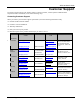
AES-100 User’s Guide Customer Support If you have questions about your ZyXEL product or desire assistance, contact ZyXEL Communications Corporation offices worldwide, in one of the following ways: Contacting Customer Support When you contact your customer support representative, have the following information ready: ♦ Product model and serial number. ♦ Firmware version information. ♦ Warranty information. ♦ Date you received your product.
AES-100 User’s Guide Table of Contents Copyright....................................................................................................................................................................................... ii ZyXEL Limited Warranty ............................................................................................................................................................. iii Interference Statements and Warnings ......................................................
AES-100 User’s Guide 5.1 ADSL Standards............................................................................................................................................ 5-1 5.2 Profiles........................................................................................................................................................... 5-1 5.3 Configured Vs. Actual Rate ...........................................................................................................................
AES-100 User’s Guide Chapter 14 Troubleshooting ................................................................................................................................................ 14-1 14.1 ADSL LED(s) ........................................................................................................................................... 14-1 14.2 Data Transmission..............................................................................................................................
AES-100 User’s Guide List of Figures Figure 1-1 MTU Application ......................................................................................................................................................1-3 Figure 1-2 ISP Application..........................................................................................................................................................1-4 Figure 2-1 AES-100 Front Panel...............................................................................
AES-100 User’s Guide List of Tables Table 2-1 Front Panel Ports of an ADSL Network Module ........................................................................................................ 2-2 Table 2-2 AES-100 Network Module LED Descriptions............................................................................................................ 2-2 Table 4-1 Logs Sent to Your UNIX Server ..............................................................................................................
AES-100 User’s Guide Preface Congratulations on your purchase of the AES-100 ADSL-Ethernet Switch. This preface introduces you to the AES-100 and discusses the organization and conventions of this user’s guide. It also provides information on other related documentation. About the AES-100 The AES-100 is an ADSL (Asymmetrical Digital Subscriber Line) to Ethernet switch. It allows you to multiplex traffic from up to 16 ADSL lines to an Ethernet network before it is forwarded to the Internet.
AES-100 User’s Guide Chapter 1 Getting to Know the AES-100 This chapter describes the key features, benefits and applications of your AES-100. The AES-100 is an ADSL (Asymmetrical Digital Subscriber Line) to Ethernet switch. It aggregates traffic from up to 16 ADSL lines to Ethernet. ADSL allows the coexistence of broadband data service and conventional voice service over the same telephone wire.
AES-100 User’s Guide IEEE 802.1Q Tagged VLAN Your AES-100 uses the IEEE 802.1Q Tagged VLAN (Virtual Local Area Network) which allows your device to deliver tagged/untagged packets to and from its ports. The AES-100 supports up to 255 VLANs and the maximum VLAN ID 4094. IEEE 802.1p Priority IEEE 802.1p Priority gives your AES-100 the ability to regenerate priority changes for ports. Fast Mode The AES-100’s fast mode makes use of the “tag” subset of the IEEE 802.
AES-100 User’s Guide 1.2 Benefits 1.2.1 MTU Application The following diagram depicts a typical application of the AES-100 is in a large residential building, or multiple tenant unit (MTU), that leverages the existing phone line wiring to provide Internet access to all tenants. A tenant connects a computer to the phone line in a unit using an ADSL modem. The other end of the phone line is connected to a port on the AES-100.
AES-100 User’s Guide 1.2.2 ISP Application The AES-100 can also be used by an Internet Service Provider (ISP) as an IP DSLAM. The AES-100 terminates all of the ADSL ATM circuits and converts the traffic to IP packets. All IP traffic goes directly to the ISP’s internal Ethernet network, before being routed to the Internet. The following diagram is an example of the AES-100 in an ISP Application. Figure 1-2 ISP Application 1.2.3 Compact Design for Limited Space The AES-100 occupies only 1.
AES-100 User’s Guide Dimensions • In mm: 440 (W) x 320 (L) x 66 (H) Weight • 6.
AES-100 User’s Guide Chapter 2 Hardware Overview This chapter gives a brief introduction to the AES-100 hardware. 2.1 Unpacking the AES-100 Before installing, check to see that all the components of the AES-100 are included in the package. 2.
AES-100 User’s Guide Figure 2-1 AES-100 Front Panel 2.3.1 Front Panel Ports The following table describes the ports on the front panel of an AES-100 network module. Table 2-1 Front Panel Ports of an ADSL Network Module PORTS DESCRIPTION LAN The LAN port is a 10/100 Mbps auto-sensing Ethernet port for connection to a router. CONSOLE The CONSOLE port is an RS-232 port for configuring the AES-100. USER 1-8 The USER port connects to the user (subscriber) ADSL equipment.
AES-100 User’s Guide 2.5 ADSL Port Connections The line from the user carries both the ADSL and the voice signals. For each line, the AES-100 has a built-in splitter that separates the high frequency ADSL signal from the voice band signal and feeds the ADSL signal to the AES-100, while the voice band signal is diverted to the CO port.
AES-100 User’s Guide Connect the female end of the power cord to the power receptacle on the rear panel of your AES-100 (just to the right of the warning sticker) as seen next. Connect the other end of the cord to a power outlet. Make sure that no objects obstruct the airflow of the fans (located on the side of the unit).
AES-100 User’s Guide Chapter 3 Factory Default Settings This section describes the factory default settings of the AES-100. 3.1 IP Parameters • IP address = 192.168.1.1 • Subnet mask = 255.255.255.0 • Default gateway = 192.168.1.254 3.2 Console Port • Baud rate = 9600 bps • Data bits = 8 • Parity = none • Stop bit = 1 • Flow control = none 3.3 SNMP Community Strings • Read = public • Write = 1234 3.4 • Console, Telnet and FTP Password 1234 (default) 3.
AES-100 User’s Guide • Maximum Downstream Rate: 8160 Kbps for G.dmt, 1536 Kbps for G.Lite • Operational Mode: auto 3.6 Ethernet Port The factory default settings for the Ethernet port of the AES-100 are: - Auto-negotiation: ON - Speed used with auto-negotiation OFF: 100Mbps - Duplex mode used with auto-negotiation OFF: half duplex 3.7 Other Factory Defaults • MACfilter: Disabled • Secured Host: Disabled • Sys Error Log: Always Enabled • UNIX Syslog: Disabled • IEEE 802.
AES-100 User’s Guide Chapter 4 System Commands This section describes basic configuration and system-related commands. 4.1 Command Line Interface (CI) The AES-100 uses text command lines as the user interface for software configuration. Before discussing the details of configuration, the rules of the commands are listed next. The command keywords are in regular courier font. 1. The command keywords must be entered exactly as shown, that is, no abbreviations are allowed. 2.
AES-100 User’s Guide 192.168.1.1 adsl> To get back to the top level prompt from a subsystem, use the home command. The remainder of this user’s guide describes CI Commands that are helpful for configuring network modules. 4.3.1 Help Facility The system includes a help facility to provide you with online assistance. • You can issue the help or ? command at any time. The system will display a list of available commands in response.
AES-100 User’s Guide 192.168.1.1> restart This command instructs the system to perform a warm start, that is, restarting the system without turning the power off and on. 4.4.4 Passwd Command Syntax: 192.168.1.1> passwd This command changes the management password. The management password is used for authentication at console or Telnet login. This command is only allowed for local console management sessions. The management password must be from 1 to 8 characters long and any character is accepted.
AES-100 User’s Guide 192.168.1.1 sys> set contact [] This command allows you to set the name of the contact person for your AES-100. The previous setting will be cleared if the command is entered with the name omitted. 4.5.4 Set Location Command Syntax: 192.168.1.1 sys> set location [] This command allows you to set the location of your AES-100. The previous setting will be cleared if the command is entered with the location omitted. 4.5.5 Set Mode Syntax: 192.168.1.
AES-100 User’s Guide 192.168.1.1 sys> secured host add where = IP address of a secured host. This command adds the IP address of a secured host. You may add up to ten IP addresses. 4.6.3 Secured Host Delete Command Syntax: 192.168.1.1 sys> secured host delete where = IP address of a secured host. This command deletes the IP address of a previously added secured host. 4.
AES-100 User’s Guide This command sets the syslog facility for the UNIX system. 4.7.3 Syslog Server Command Syntax: 192.168.1.1 sys> syslog server where = IP address of syslog server. This command sets the UNIX syslog server IP address. If =0.0.0.0 (default), then logs will be dropped (not be sent). 4.8 System Error Log Commands The system error log will record error events locally to the AES-100 memory.
AES-100 User’s Guide 4.8.3 Saving and Viewing a Previous Error Log You may save and view a previous error log after warm restarting the AES-100 (refer to Figure 4-1). 192.168.1.1> sys 192.168.1.1 sys> errlog display 0 Thu Jan 01 00:00:12 SNMPR WARN 1 Thu Jan 01 00:00:14 CONSOL INFO 192.168.1.1 sys> home 192.168.1.1> restart 192.168.1.1> fm 192.168.1.1 fm> cat errorlog 0 Thu Jan 01 00:00:12 SNMPR WARN 1 Thu Jan 01 00:00:14 CONSOL INFO Log in memory before you restart your AES-100.
AES-100 User’s Guide Chapter 5 ADSL Configuration The ADSL (Asymmetrical Digital Subscriber Line) subsystem allows you to configure and monitor the ADSL ports. 5.1 ADSL Standards The AES-100 supports both the G.lite and the G.dmt standards. G.lite is intended to minimize the cost for the consumer market. Table 5-1 Maximum Transfer Rates of the AES-100’s ADSL Ports STANDARD MAXIMUM DOWNSTREAM MAXIMUM UPSTREAM G.dmt 8160 Kbps 1024 Kbps G.lite 1536 Kbps 512 Kbps T1.413 8160 Kbps 1024 Kbps 5.
AES-100 User’s Guide Note that when you configure an ADSL port, the upstream rate must be less than or equal to the downstream rate. Note also that the list port command displays the configured parameters of the ADSL port, while the show port command displays the actual rates. 5.4 Default Settings The default profile always exists and all of the ADSL ports belong to it when the AES-100 is shipped. The default profile's name is set to DEFVAL. 5.4.
AES-100 User’s Guide 5.5 ADSL Commands 5.5.1 Config Save Command Syntax: 192.168.1.1 adsl> config save The config save command saves the ADSL configuration into nonvolatile memory. 5.5.2 Disable Port Command Syntax: 192.168.1.1 adsl> disable port where = port number, from 1 to 8 The disable port command forcibly disables the specified ADSL port. The factory default of all ports is disabled. A port must be enabled before data transmission can occur.
AES-100 User’s Guide 192.168.1.1 adsl> enable ports The enable ports command forcibly enables all ADSL ports. The factory default of all ports is disabled. A port must be enabled before data transmission can occur. An enabled but disconnected ADSL port generates more heat than an operating port. To minimize heat generation and to enhance reliability, remember to disable a port when it is not in use. 5.5.6 Linedata Command Syntax: 192.168.1.
AES-100 User’s Guide Current Operating Modes: Data Mode: ATM Service Type in operation: G.
AES-100 User’s Guide nsec-ds/nsec-us : 2060/2060 n-eb-ds/n-eb-us : 0/0 n-bbe-ds/n-bbe-us : 0/0 n-es-ds/n-es-us : 0/0 n-ses-ds/n-ses-us : 0/0 non-ses-blks-ds/non-ses-blks-us : 120878/120878 n-uas-ds/n-uas-us : 0/0 fe_loss_seconds/ne_loss_seconds : 0/0 fe_fec_seconds/ne_fec_seconds : 0/0 fast_trains : 0 fast_trains_fail : 0 These counts contain line performance data that has been accumulated since the system started.
AES-100 User’s Guide 5.5.10 List Port Command Syntax: 192.168.1.1 adsl> list port where = port number, from 1 to 8 The list port command shows the configured maximum upstream/downstream rates, the mode (or standard), and enable/disable state of an individual ADSL port. 5.5.11 List Ports Command Syntax: 192.168.1.1 adsl> list ports The list ports command shows the configured maximum rates, modes and states of all ADSL ports. 5.5.12 Set Profile Command Syntax: 192.168.1.
AES-100 User’s Guide Even though you can specify arbitrary numbers in the set profile command, the actual rate is always a multiple of 32 Kbps. If you enter a rate that is not a multiple of 32 Kbps, the actual rate will be the next lower multiple of 32Kbps. For instance, if you specify 60 Kbps for a port, the actual rate for that port will not exceed 32 Kbps, and if you specify 66 Kbps, the actual rate will not be over 64Kbps. An example is shown next. 192.168.1.
AES-100 User’s Guide 192.168.1.1 adsl> show profile where = a profile name The show profile command displays the settings of an ADSL profile. An example is shown next. 192.168.1.
AES-100 User’s Guide The mode parameter specifies the standard that this port is allowed. When set to auto, the AES-100 follows whatever mode is set on the other end of the line. When the mode is set to auto and the negotiated mode is G.lite, if the configured rates exceed those allowed by G.lite, the actual rates are governed by G.lite, regardless of the configured numbers. An example is shown next. 192.168.1.1 adsl> set port 4 debug auto This command sets ADSL port 4 to have the debug profile.
AES-100 User’s Guide 5.5.21 Set PVC Command Syntax: 192.168.1.1 adsl> set pvc [ ] where = port number, from 1 to 8.
AES-100 User’s Guide 5.5.24 Show PVCs command Syntax: 192.168.1.1 adsl> show pvcs The show pvcs command allows you to display the PVC parameters of all ADSL ports.
AES-100 User’s Guide Chapter 6 10/100M Fast Ethernet Port Commands The Ethernet subsystem allows you to configure and monitor the 10/100M fast Ethernet port. 6.1 10/100M Auto-Sensing Ethernet The AES-100 supports 10/100Mbps auto-sensing Ethernet. There are two factors related to the connection of two Ethernet ports: rate and duplex mode. In a 10/100Mbps fast Ethernet, the rate can be 10Mbps or 100Mbps and the duplex mode can be half duplex or full duplex.
AES-100 User’s Guide = 10 or 100 This command sets the connection speed used when auto-negotiation is turned off. 10 stands for 10Mbps and 100 stands for 100Mbps. 6.2.4 Status Command Syntax: 192.168.1.1 ethernet> status This command shows the current status of the Ethernet port.
AES-100 User’s Guide Chapter 7 Bridge Commands This chapter discusses the bridge subsystem. It allows you to configure and monitor the bridging, configure MAC filters, port-based VLANs and tagged frame functions of the AES-100. The AES-100 supports IEEE 802.1D transparent bridging; but not the static filtering feature or spanning tree protocol.
AES-100 User’s Guide 7.3 MACfilter Commands Use MACfilter commands to filter incoming packets based on MAC (Media Access Control) address(es) that you specify. If you do not use this command, your AES-100 will not filter packets. MACfilter commands are listed next. You may specify up to five MAC addresses per port. 7.3.1 MACfilter Command Syntax: 192.168.1.1 bridge> macfilter [] where = a bridge port number.
AES-100 User’s Guide 7.3.5 Macfilter Delete Command Syntax: 192.168.1.1 bridge> macfilter delete where = a bridge port number. = the source MAC address in "00:a0:c5:12:34:56" format. This command removes a configured source MAC address from a port specified by you. 7.4 Filter Commands 7.4.1 Filter Command Syntax: 192.168.1.1 bridge> filter This command displays the filtering database. 7.4.
AES-100 User’s Guide 0 239.255.255.250 7f-ff-fa 1, 2 1 224.000.001.022 00-01-16 1, 3, 4 2 235.001.001.006 01-01-06 1, 2, 5, 7,8 3 229.055.150.208 37-96-d0 1, 9 4 224.000.001.060 00-01-3c 1, 3, 5, 6 5 235.209.237.084 51-ed-54 1, 4, 6, 9 Total 6 entries. IGMP version 2 Query Received 343 Max Response Time 100 * 1/10 seconds Query Interval 125 seconds where ID The location of the entry in the multicast filtering database. GDA Group Destination Address.
AES-100 User’s Guide This command flushes out the filtering database of the specified bridge port. If the field is omitted, this command will flush out the filtering databases of all ports. 7.4.6 Info Command Syntax: 192.168.1.1 bridge> info This command shows the software number of the bridge implementation and the maximum size of the filtering database. 7.
AES-100 User’s Guide Figure 7-1 Default VLAN Settings 7.5.1 Portfilter Command Syntax: 192.168.1.1 bridge> portfilter [all|] where = an incoming bridge port number. all = all bridge ports are allowed outgoing ports. = the outgoing bridge ports. Separate by a space if there is more than one port. This command sets or displays the port-based VLAN configuration. An example is shown next. 192.168.1.1 > bridge 192.168.1.
AES-100 User’s Guide This example sets the allowed outgoing bridge ports of port 2 (ADSL port 1) to port 1 (Ethernet port) and port 3 (ADSL port 2). The allowed outgoing bridge ports of port 3 (ADSL port 2) are set to port 1 (Ethernet port) and port 2 (ADSL port1). This way ADSL ports 2 and 3 can communicate with each other and the Ethernet port. You can see the effects of this example by using the following command: 192.168.1.
AES-100 User’s Guide Figure 7-3 Example of Modified VLAN Port 3 The following figure illustrates that port 1 (the Ethernet port) is linked to ports 2 (ADSL port 1) and 3 (ADSL port 2). Ports 2 (ADSL port1) and 3 (ADSL port 2) are also linked to each other. Or, in other words, the following figure is a result of the following commands: 192.168.1.1 bridge> portfilter 2 1 3 192.168.1.1 bridge> portfilter 3 1 2 Figure 7-4 Example of Modified VLAN Settings 7.
AES-100 User’s Guide This command lets you allocate IEEE 802.1Q identification numbers (tags) on a port-by-port basis. The command 192.168.1.1 bridge> pvid displays the default port identification of all ADSL Networking Module ports. The IEEE 802.1Q standard uses an explicit tag in the header to specify the VLAN ID (VID) of an Ethernet frame. In this way, the VLAN membership of a frame can be carried across switches.
AES-100 User’s Guide Chapter 8 IEEE 802.1Q Tagged VLAN Commands This chapter generally describes the IEEE 802.1Q Tagged VLAN and associated CI Commands. 8.1 Introduction The IEEE 802.1Q Tagged VLAN allows your ADSL Networking Module to deliver tagged/untagged frames to and from its ports. The standard gives the ADSL Networking Module the ability to recognize VLAN-aware and VLANunaware devices and automatically strips tags off of frames destined for ports that would normally drop tagged frames.
AES-100 User’s Guide 8.4.2 Dynamic Entries (DVLAN Table) Dynamic entries are learned by the bridge and cannot be created or updated by management. The bridge learns this information by observing what port, source address and VLAN ID (or VID) is associated with a frame. Entries are added and deleted using GARP VLAN Registration Protocol (GVRP), where GARP is the Generic Attribute Registration Protocol. 8.5 IEEE 802.
AES-100 User’s Guide pvid port# --------1 1 1 2 1 3 1 4 1 5 1 6 1 7 1 8 1 9 192.168.1.1 vlan1q> Figure 8-1 Example: PVID Command Display 8.5.4 SVLAN CPU Command Syntax: 192.168.1.1 vlan1q> svlan cpu [] where = VLAN ID. Valid parameter range = [1 – 4094]. This command registers your CPU as a port member of the static VLAN with . To display the CPU static VLAN identification, simply enter this command without parameters, as shown next. 192.168.1.1 vlan1q> svlan cpu 8.5.
AES-100 User’s Guide 8.5.6 SVLAN Setentry Command Syntax: 192.168.1.1 vlan1q> svlan setentry where = VLAN ID. Valid parameter range = [1 – 4094]. = bridge port number. Valid parameter range = [1 – 9]. = Registrar administration control flag. Valid parameters = [fixed, forbidden, normal]. Select fixed to register a to the static VLAN table with .
AES-100 User’s Guide Forwarding Process Example The switch uses the SVLAN in making frame-forwarding decisions. First the switch checks the MAC address in a frames header against the MAC filtering database. Next the switch checks the VLAN ID (VID) of tagged frames or assigns temporary VIDs to untagged frames (see the PVID Command). The switch then checks the VID in a frame’s tag against the SVLAN table.
AES-100 User’s Guide The switch sees that port #s 2, 3, 4, 6, 8 and 9 (ADSL ports 1, 2, 3, 5, 7 and 9) are all set to “fixed” and “untag” which means the SVLAN allows the frame to be sent to those ports without a tag. Port # 5 is “forbidden” so the frame is not forwarded to adsl port # 4. Port # 7 (ADSL port 6) is “normal” which means that it was entered dynamically, so the frame is permitted to be forwarded to port # 7 if port # 7 is registered in the DVLAN table.
AES-100 User’s Guide 8.5.9 DVLAN List Command Syntax: 192.168.1.1 vlan1q> dvlan list This command displays the dynamic VLAN registration table. The following figure is an example of what is displayed when you use this command.
AES-100 User’s Guide vid ---1 01 ---O V 02 ---- X X O X X X 2 3 03 ---O X X O V 04 ---X O X X 05 ---O X 06 ---- X O X X O X X 07 ---O X 08 ---- 09 ---- X X X X X X X V Figure 8-8 Example: VLAN List Command Display In the figure above “O" denotes “egress port”, “V” denotes “tagged” and “X” denotes “ untagged”. 8-8 IEEE 802.
AES-100 User’s Guide Chapter 9 IEEE 802.1p Priority Commands This chapter explains IEEE 802.1p Priority CI Commands. 9.1 Introduction IEEE 802.1p Priority CI Commands provide priority regeneration for ports. IEEE 802.1p defines up to eight priorities (0-7) by inserting a tag into a MAC-layer frame that contains bits to define priority of service. 9.2 IEEE 802.
AES-100 User’s Guide This command sets the mapping of incoming user priority to a regenerated user priority for an ingress port. To display the regeneration table, simply use the Regen Port command without parameters, as shown next. 192.168.1.1 vlan1q> regen port 9-2 IEEE 802.
AES-100 User’s Guide Chapter 10 IP Commands This chapter shows you how to configure the IP (Internet Protocol) parameters. The IP host implementation in the AES-100 allows you to manage it over the network. More often than not, you have more than one AES-100 for a particular installation. Before you start configuring the AES-100s, make sure that you 1. Plan ahead. 2. Have a complete diagram showing the whole network. 3. Record the IP parameters assigned to the equipment in your network. 10.
AES-100 User’s Guide For example, if you want the AES-100 to have 172.21.100.1 as the IP address, 255.255.255.0 for the subnet mask and 172.21.100.254 for the default gateway, you may use the following command sequence: 192.168.1.1> ip 192.168.1.1 ip> device delete ether 192.168.1.1 ip> device add ether ether //bridge 172.21.100.1 192.168.1.1 ip> subnet delete ether.home 192.168.1.1 ip> subnet add ether.home ether 172.21.100.0 ff:ff:ff:00 192.168.1.1 ip> route delete default 192.168.1.
AES-100 User’s Guide 192.168.1.1> ping [ []] where host = the IP address of the target. ttl = Time to Live (optional). This parameter limits the number of hops (routers) that the echo request can travel before it reaches the target. size = The parameter specifies the size of the payload, that is, not counting the headers, of the echo request. The default size is 32 octets.
AES-100 User’s Guide Chapter 11 Remote Management This chapter shows you how to manage the AES-100 remotely. More often than not, you will have the AES-100 located remotely making its remote management features very useful. 11.1 Management by Telnet After you have set up the IP parameters and connected the AES-100 to the network, you can manage it remotely with telnet. You can use any telnet client that you find convenient.
AES-100 User’s Guide An agent is a management software module that resides in a managed device (the AES-100). An agent translates the local management information from the managed device into a form compatible with SNMP. The manager is the station through which network administrators perform network management functions. It executes operations that control and monitor the managed devices. The managed devices contain objects that define each piece of information to be collected about a device.
AES-100 User’s Guide This command allows read-only or read-write access. If the IP address is specified, access is allowed for the manager station with that address only. 11.3.2 SNMP Access Delete Command Syntax: 192.168.1.1 snmp> access delete [] This command revokes SNMP access by the specified community (password). If the IP address is specified, access is denied for that manager station only. 11.3.3 SNMP Access Flush Command Syntax: 192.168.1.
AES-100 User’s Guide ♦ overheatOver Trap (defined in ZYXEL-MIB) : This trap is sent periodically when the ADSL Networking Module is no longer overheated. 11.4.2 Trap Add Command Syntax: 192.168.1.1 snmp> trap add [] where = The password used by the ADSL Networking Module to authenticate itself to the trap server. = The IP address of the trap server.
AES-100 User’s Guide Chapter 12 Configuration Backup/Restore This chapter describes the process for backing up your user settings (configuration) from the ADSL Networking Module onto your computer and how to restore them to the ADSL Networking Module. The ADSL Networking Module uses FTP for configuration backup/restore through its built-in FTP server. You can use any FTP client (for example, ftp.exe in Windows) to backup/restore the ADSL Networking Module’s configuration. 12.
AES-100 User’s Guide Do not turn off the ADSL Networking Module during the restore process, as it may corrupt the firmware and make your ADSL Networking Module unusable. Step 1. Connect to the ADSL Networking Module with your favorite FTP client. The command is generally C:\> ftp at the computer command prompt. Step 2. Enter the User name (just press [ENTER]). User: Step 3. Enter the management password (1234 by default).
AES-100 User’s Guide Chapter 13 Firmware Upload and Recovery ZyXEL periodically releases new firmware for the ADSL Networking Module for bug fixes and enhancements. Please check the web site at www.zyxel.com every now and then for the latest firmware release. The ADSL Networking Module uses FTP to upload firmware and no longer supports TFTP uploads. If the firmware in non-volatile memory is damaged, the ADSL Networking Module uses BOOTP/TFTP to recover the firmware.
AES-100 User’s Guide 3. Enter the management password (1234 by default). For example, Password: 1234 230 Logged in 4. Transfer the firmware file to the ADSL Networking Module. For example, ftp> put 201AS0b1.img image where 201AS0b1.img = The firmware file that you want to upload. image 5. = The internal firmware name in the ADSL Networking Module. Quit FTP. For example, ftp> quit Wait for the update to finish. The ADSL Networking Module restarts automatically.
AES-100 User’s Guide Figure 13-1 BOOTP/TFTP Server 5. The Input Box window will pop up as shown next. Type the MAC address of the ADSL Networking Module and then click OK. You can find the MAC address of the ADSL Networking Module on its boot console. Figure 13-2 Input MAC 6.
AES-100 User’s Guide Figure 13-3 Database Edit Dialog 7. Select Normal Bootp to enable normal BOOTP/TFTP functions. Figure 13-4 Enable BOOTP/TFTP 8. Restart the ADSL Networking Module and press any key within three seconds to get the following screen. SDRAM Testing ... Mac address 00:A0:C5:12:34:56 Press any key within 3 seconds to enter debug mode ............................. Figure 13-5 Enter Debug Mode 9.
AES-100 User’s Guide 11. Wait for the firmware upload to finish. 12. Use the following command sequence on the ADSL Networking Module to write new firmware to flash memory. 192.168.1.1> flashfs 192.168.1.1 flashfs> wipe 192.168.1.1 flashfs> update 13. Wait for the update to complete and then restart the ADSL Networking Module.
AES-100 User’s Guide Chapter 14 Troubleshooting This chapter covers potential problems and possible remedies. After each problem description, some steps are provided to help you to diagnose and to solve the problem. 14.1 ADSL LED(s) An ADSL LED is not on.
AES-100 User’s Guide 14.3 ADSL LED(s) turn On and Off An ADSL LED turns on and off intermittently. Table 14-3 Troubleshooting a Non-Constant ADSL LED STEPS CORRECTIVE ACTION 1 Unplug the phone wire coming from the USER port of the AES-100 and connect the user’s ADSL modem or router directly to the USER port of the AES-100 using a different telephone wire. If the ADSL LED stays on, check for a problem with the building’s phone wire.
AES-100 User’s Guide 14.6 Password I forgot the password to my AES-100. Table 14-6 Troubleshooting the Password OPTIONS CORRECTIVE ACTION 1 Send a screen shot of your AES-100’s MAC address to your local distributor. 2 Refer to the BOOTP/TFTP Firmware Update section to update your firmware. All settings will return to default value, so any configurations you have made will be lost. 14.7 Remote Server The user’s computer behind the ADSL modem or router can not access a remote server.
AES-100 User’s Guide 14.9 Telnet I can not telnet into the AES-100. Table 14-9 Troubleshooting Telnet STEPS CORRECTIVE ACTION 1 Make sure that a telnet session is not already operating. The AES-100 will only accept one telnet session at a time. 2 Ping the AES-100 from your computer. If you are able to ping the AES-100 but are still unable to telnet, contact the distributor. If you cannot ping the AES-100, check the IP addresses in the AES-100 and your computer.
AES-100 User’s Guide Index 1 Configuration 10/100M Auto-Sensing Ethernet............................ 6-1 Backing up........................................................ 12-1 A Restoring .......................................................... 12-1 AC INPUT ............................................................. 2-4 Configuration Backup/Restore............................. 12-1 Access Delete Command ..................................... 11-3 Connections Access Flush Command ............
AES-100 User’s Guide FCC .......................................................................... iv IEEE 802.1Q Tagged VLAN ....1-2, 4-4, 7-8, 7-9, 8-1 FCC Rules ................................................................ iv Commands ..........................................................8-1 Federal Communications Commission (FCC) Interference Statement .......................................... iv Default ................................................................3-2 Filter Command...
AES-100 User’s Guide Enable ................................................................. 7-2 Related Documentation............................................ xi Filter ................................................................... 7-2 Remote Firmware Upload .................................... 13-1 Status .................................................................. 7-2 Remote Management ........................................... 11-1 Management........................................
AES-100 User’s Guide Splitters Enable/Disable Logs...........................................4-5 Integrated Splitters..............................................1-1 Logs Lost ............................................................4-5 Statistics Command..............................................10-3 Logs Sent ............................................................4-5 Status Command............................................. 6-2, 7-1 Unpacking ..........................................